What is the best way to program a PLC?
My answer is simple. The best way is one in which someone can look at your program and understand it. I cannot stress the need for good documentation of your program enough. The best programs are ones that I can return to after several years and understand what it is doing within a few minutes. Programs should read like a book. This will aid in troubleshooting, modifying, or teaching.
How do you approach a PLC program?
You must know everything about the logic or process before starting your program. Making a flow chart is one exemplary method of learning logic and strategy. The flow chart will bring out questions like the following:
What happens after a power outage? (In each condition of the outputs)
What happens if a sensor is not made? How long do you wait?
What are the critical items to monitor? (Ex. Air Pressure, Weight, Length, etc.)
What happens…
Once you have written your program and are in the troubleshooting stage, you can usually go back and add to your flow chart. Usually, something needs to be added, changed, or modified based on the actual functioning of the program.
Consider each project a complete learning opportunity.
Once you know what you want to do with the PLC and understand the logic flow well, it is time to start coding. Remember that there is no right or wrong method to program the PLC; either the program will work or it will not work.
Let’s look at an example. We will start with something that we all know how works.
Traffic Lights
We will look at three programming examples for the lights. Two different approaches to programming will be used, but the program function is the same. The last example will modify the logic for a car being sensed.

You will notice that this program is fully documented and easy to understand.
This program is based on time events. The base rate is one second. If we create a list of what the outputs look like after each second and then send them to the physical output channel, we will have the second type of approach to this logic…
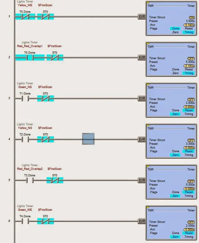
Sample program for traffic light intersection with lights facing North /South and West /East.
Green is on for 5 seconds
Yellow is on for 2 seconds
Red has an overlap of 3 seconds
This program uses indirect addressing to program
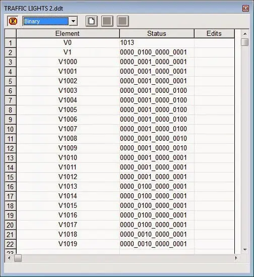
Let’s look at the list of outputs we want based upon the following addresses: (Notice the Bit location)
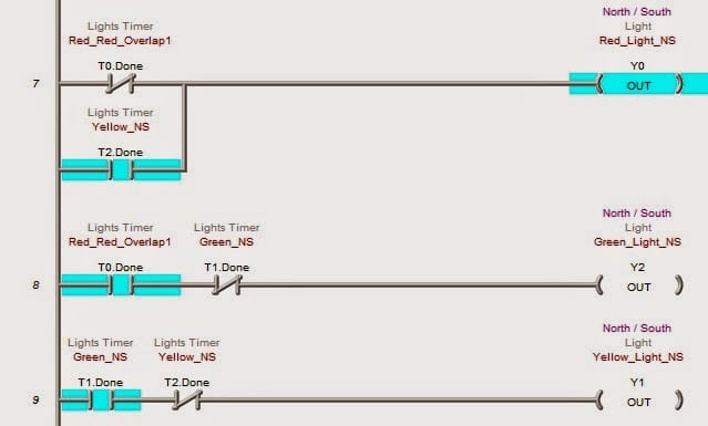
Y0 – Red_Light_NS
Y1 – Yellow_Light_NS
Y2 – Green_Light NS
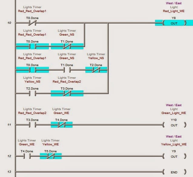
Y8 – Red_Light_WE
Y9 – Yellow_Light_WE
Y10 – Green_Light_WE
We have 20 steps in the sequence based upon 1-second increments. (V1000 to V1019)
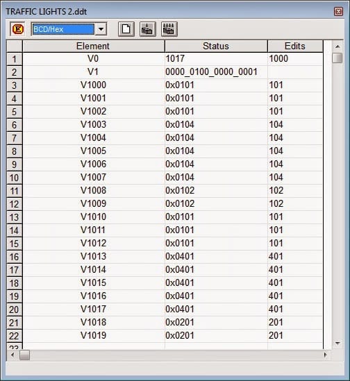
Here is what the hex values translated to binary look like:
(Review of numbering systems from the previous blog)
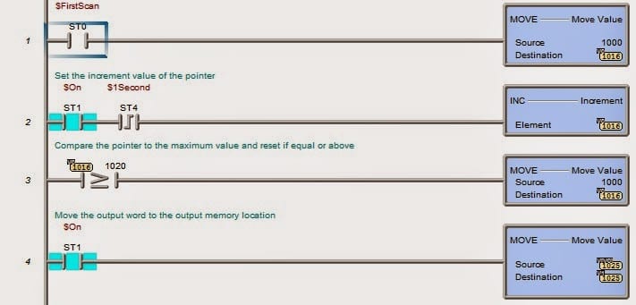
The $FirstScan bit will reset the pointers, so if power is lost, the lights will start with a Red / Red overlap before starting the sequence again.
Let’s look at the program:
The $FirstScan bit will move the number 1000 into V0. V0 will act as our pointer for the list of outputs. (V1000 to V1019)
Every 1 second ($1Second), V0 will increment by a value of 1. We will then compare the value to 1020, which indicates the end of the sequence. If the value is greater or equal, our pointer is reset to 1000. This is done by moving the number 1000 into V0.
The last step is moving our output word indirectly, V0, to our output word V1. Indirectly, the value in V0 will point to a memory location dictated by the number it contains.
ex: V0 has a value of 1000 so this means that V[V0] will move V1000 into our output word.
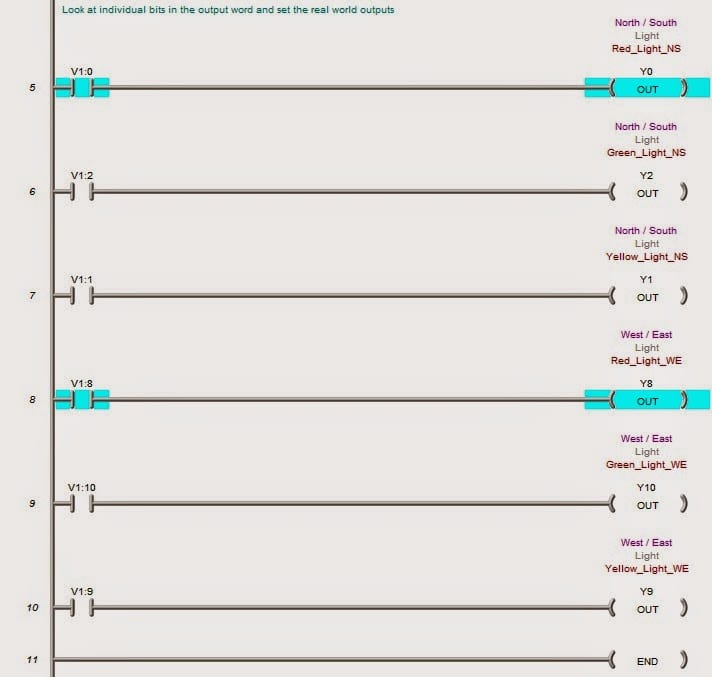
Set the outputs
Our physical outputs are set by casing our output word (V1) into bits. Depending on the programmable controller, this can be done by moving to a word that can be addressed by bits, or in our case; we can cast the word into bits. [V1:#]
This program code is much smaller than the first using discrete bits and timers. With documentation, it is also easier to read.
One advantage of indirectly addressing the program is that it makes modifications easier. Let’s modify the last program…
The North will stay green until a car approaches from the West. It will remain green for one more second before turning yellow and completing the cycle. If the vehicle is always there, then the lights will always function.
X0 – Car West/East
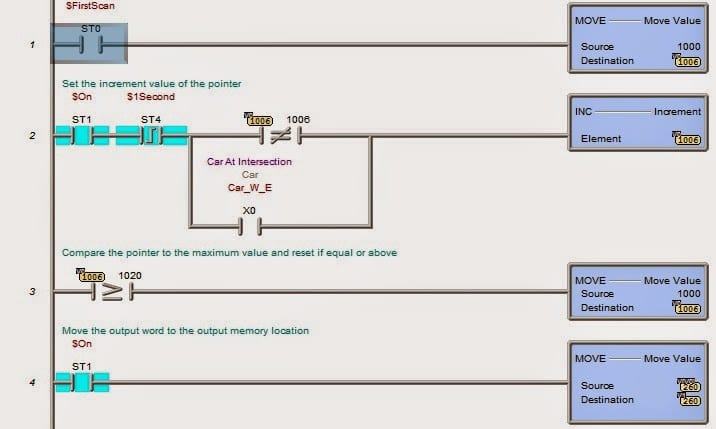
Just a couple of contacts have been added to the logic on the line that increments the pointer. The setting of the outputs does not change.
If the value at V0 is equal to 1006, then stop incrementing V0. X0 (Car at intersection) comes, then the pointer will increment. The cycle will complete and continue until X0 is not present. It will then stop when the pointer V0 equals 1006 again.
Watch on YouTube: Building a PLC Program That You Can Be Proud Of
In part 2, we will look at indirect addressing with an event-driven sequence, not timed like the above.
Contact me for the above programs. I will be happy to email them to you.
If you have any questions or need further information, please get in touch with me.
Thank you,
Garry
ACC Automation
You can download the software and simulator for free at the following address. Also listed are helpful guides to walk you through your first program.
Do-more Designer Software
How to use videos for Do-more Designer Software
One of the better PLC programming books is PLC Programming for Industrial Automation by Keven Collins. Here is the link to the free download.
If you’re like most of my readers, you’re committed to learning about technology. Numbering systems used in PLCs are not challenging to learn and understand. We will walk through the numbering systems used in PLCs. This includes Bits, Decimals, Hexadecimal, ASCII, and Floating Points.
To get this free article, subscribe to my free email newsletter.
Use the information to inform other people how numbering systems work. Sign up now.

The ‘Robust Data Logging for Free’ eBook is also available as a free download. The link is included when you subscribe to ACC Automation.
where can i find the actual code?
Hi Maciek
https://www.dropbox.com/s/yr3lgqnjqtbh3fv/Traffic%20Lights%203.zip?dl=0
The above is the link that will take you to the traffic light program.
Regards,
Garry
hi!What voltage level can the input voltage of the PLC power supply be? Which is more appropriate?
Hi capacitor,
The input to the BRX Do-More PLC that I am using for this example is 120 to 240 VAC. Looking at the specifications the range that it would accept is 85 to 264 VAC with an operating frequency between 47 and 63 Hz.
Do-more BRX Series PLCs (Stackable Micro Brick)
This link will take you to the Automation Direct website for the BRX PLC. If you type in or filter to the exact model, you will be able to see the specifications for the unit.
I hope this helps you out.
Regards,
Garry