
In part 1, we looked at writing PLC programs to control a traffic light using discrete bits and timed sequencing using indirect addressing. Part 2 used indirect addressing for inputs and output to control the program’s sequence of pneumatic (air) cylinders. We will now return to the traffic light application and expand our program significantly.
Building the Traffic Light Sequence – PLC Program Part 3
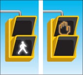
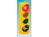
Let’s build on the traffic light sequencing used in part one with pedestrian and car detection inputs. Advanced green (flashing) will be used when the traffic is detected in the turning lane during off-peak hours. We will also throw in the time of day so that an advanced arrow will be used during weekday peak hours.
Programming using this sequencing method requires much time upfront before starting the PLC program. However, this method makes the program easier to understand, troubleshoot and modify in the future.
Remember that the PLC programmer must know everything about the machine and operation before programming.
If we start writing code, we will constantly correct and modify it based on trial and error. I use a spreadsheet program to plot the inputs, outputs and mask tables. We will go into the details of this below.
Let’s look at the inputs – Building PLC Program Part 3
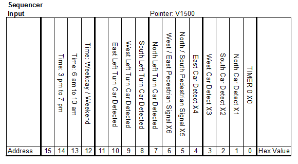
We set up the input table in words V0 to V499. Each bit in the table will be compared to the signals coming to the actual signals wired or programmed in the PLC.
Bit 0 is the time input that will control the entire program interval. Next, we have the Car Detection signals on Bits 1 to 4. The pedestrian signals are pushbuttons coming from Bits 5 and 6. The left turn signals are located in Bits 7 to 10. The real-time clock functions will come from Bits 12 to 15.
Let’s look at the outputs – Building PLC Program Part 3
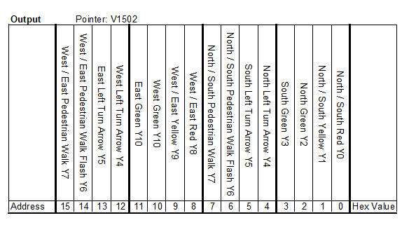
The output table will be in words V1000 to V1499. The input word will be compared to the actual inputs, and the corresponding output channel will be moved to the outputs. All of the output bits control lights. You will notice that there is a green light for each direction. This will give us the most incredible flexibility when writing our PLC program. Pedestrian signals have a flashing output bit and just an output bit. There will be only one output, but this bit will determine if it is flashing.
Masking Inputs – Building PLC Program Part 3
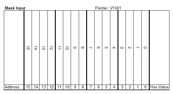
The masking table will be in words V500 to V999. The masking bits will correspond directly to the input table bits. Using the mask will allow us to ignore the status of certain bits when using the compare instruction and to set the outputs.
The Mask table will be used using an ‘AND’ word instruction. If the mask bit is on for the input, it will be used in the compare instruction. If the mask bit is off for the input then the value is always off using the compare.
Example:
1 ‘AND’ 1 = 1
1 ‘AND’ 0 = 0
0’AND’ 1 = 0
0 ‘AND’ 0 = 0
Once this is all laid out in the spreadsheet, we can start filling out our sequence of events. Fill in the events based on the time frame from input bit 0. This exercise can be a struggle because you must know precisely what you want the sequence to be to fill out the table. I usually start by thinking about what happens when power is applied to the unit for the first time.
Next time, we will continue writing the code to do what our tables want. A review of the numbering systems can be found in this post. A spreadsheet copy can be obtained at the PLC Traffic Sequence link.
Part 4 will continue with the programming of the logic in the PLC.
If you have any questions or need further information, please get in touch with me.
Thank you,
Garry
If you’re like most of my readers, you’re committed to learning about technology. Numbering systems used in PLCs are not challenging to learn and understand. We will walk through the numbering systems used in PLCs. This includes Bits, Decimals, Hexadecimal, ASCII, and Floating Points.
To get this free article, subscribe to my free email newsletter.
Use the information to inform other people how numbering systems work. Sign up now.

The ‘Robust Data Logging for Free’ eBook is also available as a free download. The link is included when you subscribe to ACC Automation.
My brother has a tech company and wanted to use PLC programming for things to be organized. It was explained here that a PLC program can be used for indirect addressing. Furthermore, it’s recommended to hire professionals for quality PLC programming.
Hi Gillian,
Anyone can learn PLC program. At no time have I recommended to hire professionals for PLC programming. In fact I encourage people to learn PLC programming.
https://accautomation.ca/programming/plc-beginners-guide/
I have removed the link in your comment for “professional services” that you offered.
Garry