The C-More Micro HMI Panel software has a simulation mode. This simulator will allow you to test your project before transferring it to a panel. Testing your application is a vital step in HMI program development. This feature of the software will save you time and money especially if your hardware is not available.
The simulator will display two windows. There is a graphical display of your HMI panel and a simulation control window. The control window will allow you to control variables in the project similar to a PLC.
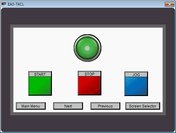
We will be looking at our program developed last time (Common Control Menu) and use the simulator to mimic how the PLC and HMI Panel will communicate in the field. This will help to detect any problems before we transfer to our panel. Let’s get started.
Previously in this C-More Micro HMI Panel series we have done the following:
System Hardware – Video
Installing the Software – Video
– Update Automation Direct Software C-More Micro HMI Video
System Setup Screens – Video
First Program – Video
First Program Part 2 (PLC < – > Panel) – Video
Common Screen Menu – Video
Call the Simulator – C-More Micro
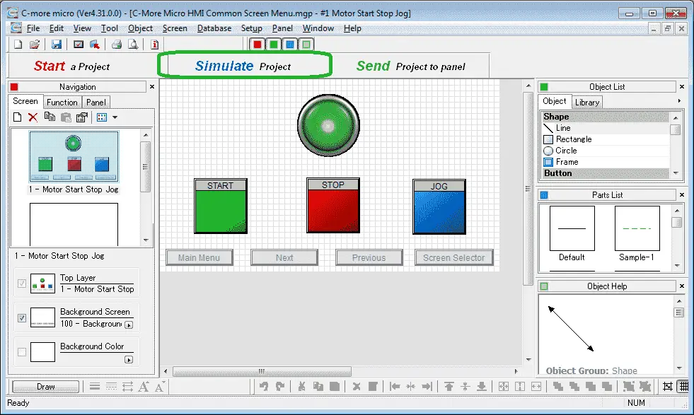
On the main screen select Simulate Project.
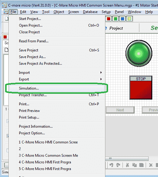
You can also call the simulator by using the main menu | File | Simulation…

The simulator will start by compiling and then displaying two windows.
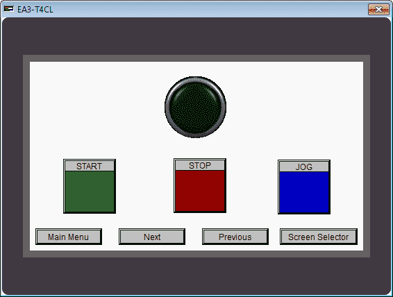
The screen simulator will display the screen information. We can use the mouse to click and simulate our inputs just as the operator would do in the field.
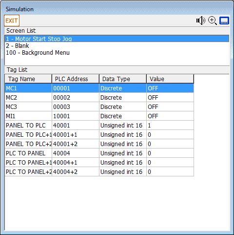
The simulator control window will show all of the pages (Screen List) in our project. It will also show the discrete on/off and registers that we have programmed. Double clicking on the discrete I/O will toggle the value from OFF to ON or vice versa. We can also change the value of any register by double clicking and then editing the value.
C-More Micro Simulating the Project
The simulator will not do our program logic. In our example we have a start, stop, jog circuit. The simulator will show inputs and outputs turning on or off but will not simulate the program in our PLC.
Example:
Starting our Motor:
Clicking on the START button on our simulator will turn on MC1 input on our simulator control.
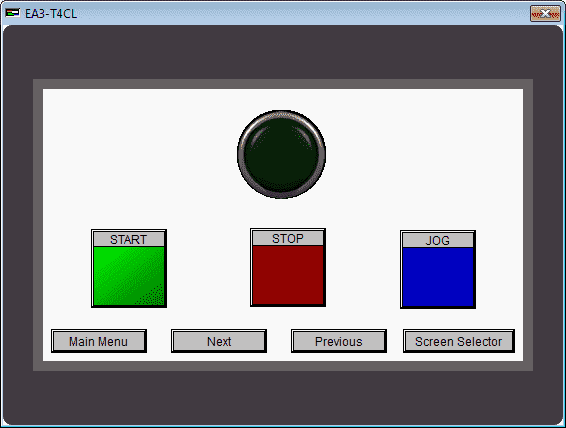
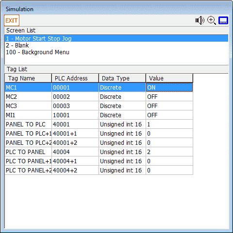
When we release the mouse button the discrete MC1 bit will then turn off.
To turn on the Motor output we need to double click on MI1.
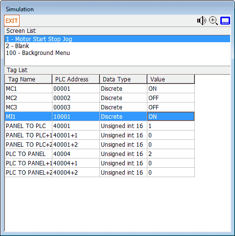
This will turn on the MI1 discrete bit.
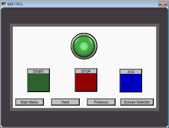
The motor indication lamp will now be lit on our screen simulator.
Panel to/from PLC Communications – C-More Micro
We previously set up the Panel to PLC communication in Modbus addresses 40001 to 40003.
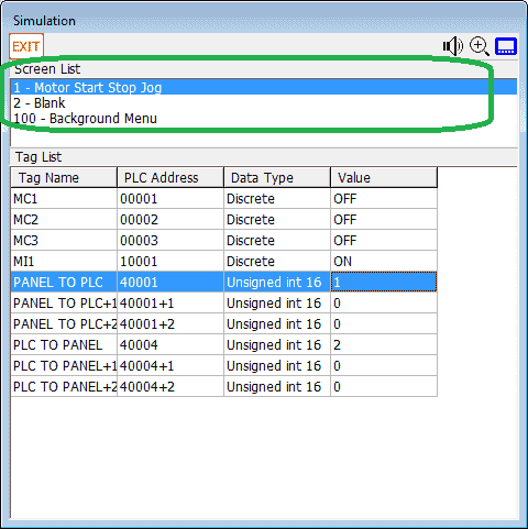
The screen list will show all of the pages programmed in the HMI panel. We can change pages by clicking the page that we want form the list. (2 –Blank)
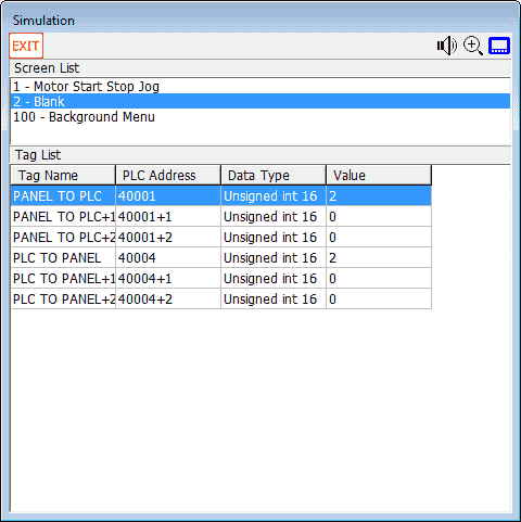
You will see that the page will now display our blank screen. Only the addresses associated to the page will be displayed on our Simulator control screen.
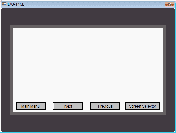
The PLC to Panel communication is Modbus addresses 40004 to 40006.
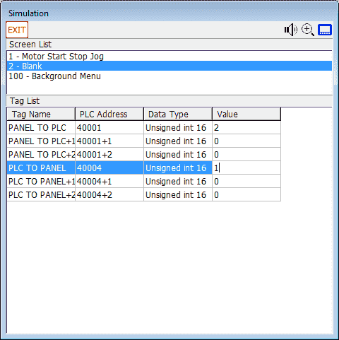
We can change the page to 1 by double clicking on address 40004 and entering the value of 1.
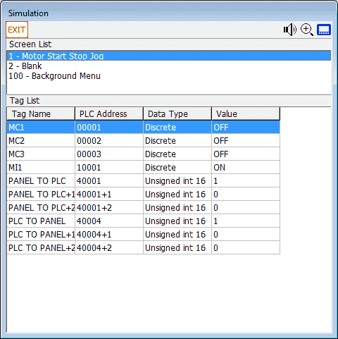
Page 1 is now displayed. We could also test the beep at address 40006. You will see that you can easily ensure that your screen program will work as expected in the field.

Download the PLC and C-More Micro program here.
Watch the video below to see the simulator in action on our C-More Micro HMI Panel.
C-More Micro Panels from Automation Direct
https://www.automationdirect.com/adc/Shopping/Catalog/HMI_(Human_Machine_Interface)/C-more_Micro_Panels
C-More Micro – Graphic Panel (EA3 Series) User Manual and Quick Start Guides
https://cdn.automationdirect.com/static/manuals/ea3mguserm/ea3mguserm.html
EA3-T4CL C-More Micro Specifications
https://cdn.automationdirect.com/static/specs/ea3t4cl.pdf
C-More Micro Programming Software V4.30
http://support.automationdirect.com/products/cmoremicro.html
This free software will enable you to program all of the C-More Micro HMI units. It includes a simulator for your application.
Next time we will look at the built in objects in the C-More Micro HMI Panel.
Watch on YouTube: C-More Micro HMI Simulate Project
If you have any questions or need further information please contact me.
Thank you,
Garry
If you’re like most of my readers, you’re committed to learning about technology. Numbering systems used in PLC’s are not difficult to learn and understand. We will walk through the numbering systems used in PLCs. This includes Bits, Decimal, Hexadecimal, ASCII and Floating Point.
To get this free article, subscribe to my free email newsletter.
Use the information to inform other people how numbering systems work. Sign up now.
The ‘Robust Data Logging for Free’ eBook is also available as a free download. The link is included when you subscribe to ACC Automation.

