
Programming a PLC can sometimes be a daunting task. The best method is to break the task into smaller steps. These are the steps that I have used for years to develop PLC programs. We will apply them to a die-stamping application.
Step 1 – Define the task:
What has to happen? This is written down and summarized. You may have to ask several different people how the machine operates—going back to individuals when there is a conflict on specific aspects of the operation. This step is number one for a reason with PLC program development.
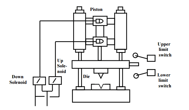
Two sensors: an upper limit switch that indicates when the piston is fully retracted and a lower limit switch that indicates when the piston is fully extended. A master switch is used to start the process and shut it down. When the master switch is turned on, the piston reciprocates between the extended and retracted positions. This is achieved with an up-and-down solenoid. When the master switch is turned off, the piston returns to the retracted position, and all solenoids are off.
Step 2 – Define the Inputs and Outputs:
Based on the information in step 1, you determine the inputs and outputs to the PLC required to develop what has to happen.
Inputs:
Master Switch – On/Off
Upper Limit Switch – On/Off
Lower Limit Switch – On/Off
Outputs:
Down Solenoid – On/Off
Up Solenoid – On/Off
Step 3 – Develop a logical sequence of operations:
This is where the majority of time is spent in PLC program development. Steps 1 and 2 allow you to systematically express what has to happen in the PLC program. Based on the logic, you may have to modify the program’s inputs/outputs or sequence. This is the most accessible place to make changes.
You can use anything to understand the logic of the operation before programming fully. This can be done using a flow chart or sequence table. Many people do not use this step and jump straight to programming.
Fully understanding the logic before starting to program can save you time and frustration.
Sequence Table: The following is a sequence table for our die stamping application. I usually review this sequence with the person with the most knowledge of the machine. This can be the designer or the machine operator.
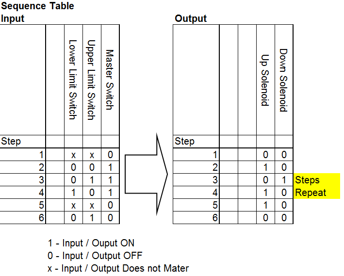
Read the Sequence Table: Follow the steps from left to right, top to bottom. Inputs and outputs are labeled as 1 (ON), 0 (OFF), or X (Does not Matter). Step 1 indicates that it does not matter the upper and lower limits switch positions. The master switch is off, so the up and down solenoids are off. Steps 3 and 4 repeat themselves as long as the master switch is on.
Note: You will notice that at step 2 after the master switch turns on, the up solenoid will be activated. So the piston always retracts when the master switch is first turned on. This operation was picked up in the development of our logical sequence.
Step 4 – Develop the PLC program:
Utilizing the above steps, we will now actually write the plc program. This can be in several different languages. In our case, ladder logic will be used.
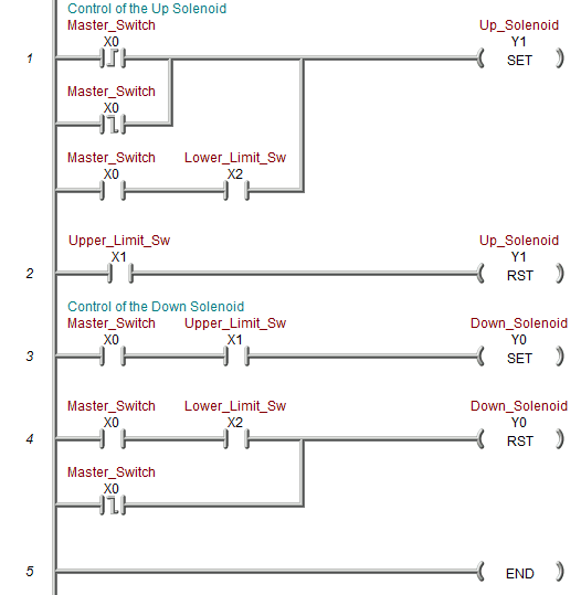
Look at the sequence table for the following logic. I have used Set and Reset conditions so the sequence table quickly follows it. When the master switch turns on, the up solenoid is activated. Notice the first rung is a direct correlation. Follow the rest of the sequence table with this ladder logic.
The document, Document, Document This is a vital part of every program, saving you time and money when you must return to the program years later.
Step 5 – Test the program:
Test the logic that you have developed. Once again, the previous steps are helpful in this process. PLC program development testing is an important step to test for all logic conditions. (Power Cycle, Sensors Fail, Safety, etc.)
Test the program with a simulator or actual machine. Make modifications as necessary. Check with the people most knowledgeable about the device to see if it is doing what they expect. Do they need anything else? Follow up after a time frame to see if any problems must be addressed.
These five steps will help you in your PLC program development.
- Define the task
- Define the inputs and outputs
- Develop a logical sequence of operation
- Develop the PLC program
- Test the program
The five steps form the basis of all PLC development. You will notice that the actual programming does not occur until the second last step. Usually, more time is spent understanding the task and sequence of operation.
Watch on YouTube: Five Steps to PLC Program Development
If you have any questions or need further information, please get in touch with me.
Thank you,
Garry
If you’re like most of my readers, you’re committed to learning about technology. Numbering systems used in PLCs are not challenging to learn and understand. We will work through the numbering systems used in PLCs. This includes Bits, Decimals, Hexadecimal, ASCII, and Floating Points.
To get this free article, subscribe to my free email newsletter.
Use the information to inform other people how numbering systems work. Sign up n w.

The ‘Robust Data Logging for Free’ eBook is also available for free download. The link s included when you subscribe to ACC Automation.