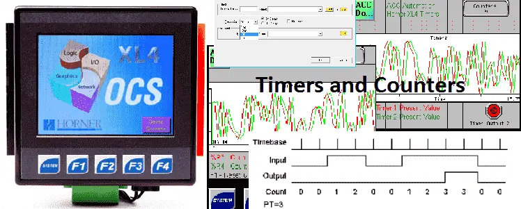
Timers and counters are used in the majority of PLC programs. We will not look at how timers and counters can be programmed in the Horner XL4 OCS all-in-one controller.
Previously we discussed the following in our Horner XL4 Series:
System Hardware
Installing the Software Cscape
Cscape Software Setup
Establishing Communication
Numbering System and Addressing
User Interface
Timers – Horner XL4
The secret of using timers is a good place to start. This post will walk through a timing chart, so you can implement your own logic.
https://accautomation.ca/the-secret-of-using-timers/
The Horner XL4 has one timer instruction in its instruction set. The options in this instruction allow us to setup On Delay, Retentive On Delay, or Off Delay timers.
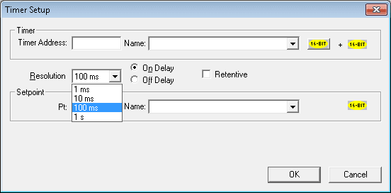
They can have a time base rate of 1ms, 10ms, 100ms, or 1s. The timer can also be either 16bit or 32bit. This determines the maximum time that we can have for the timer.
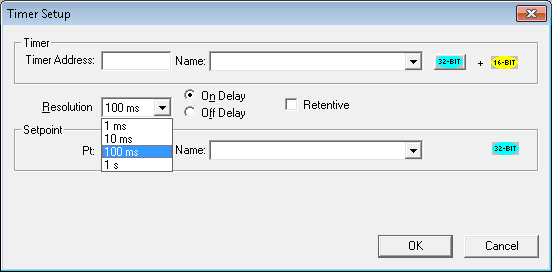
Note: You will notice that the 16bit timer requires two consecutive registers in memory and the 32 bit requires three. This is because the second/third register is used for internal use. See the help in the Cscape software for more information.
On Delay Timing Chart
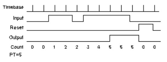
On Delay Retentive Timing Chart
Off Delay Timing Chart
Let’s take a look at an example of a flip-flop timer. This would be a timer the turns on for 5 seconds and then off for 5 seconds.
Here is the ladder logic for our timer.
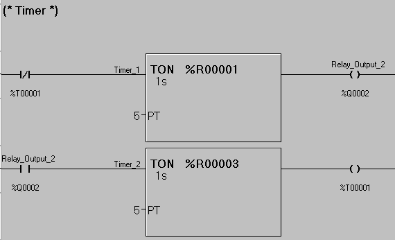
If temporary bit %T00001 is not on then Timer_1 starts to time. The time base is set for 1 second. The present value is set in register %R00001 and the set value is set for the integer value of 5. Once 5 seconds expire the Relay_Output_2 (%Q0002) turns on. This will then allow Timer_2 to start. Timer_2 has a set value of 5 seconds and the present value is in register %R00003. Once Timer_2 times out the output temporary bit %T00001 will then turn on. This will then turn off Timer_1 and Timer_2 resetting both timers. The sequence will then start again.
Note: Timer_1 uses registers %R00001 and %R00002 . Timer_2 uses registers %R00003 and %R00004
Counters – Horner XL4
The secret of using counters is another post that will give you background information on using counters.
https://accautomation.ca/the-secret-of-using-counters/
The Horner XL4 has one counter instruction in its instruction set. The options in this instruction allow us to set up either an Up Counter or Down Counter.
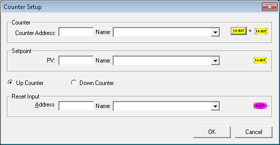
Like the timer instruction, we can also set up 32-bit counters.
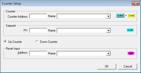
Note: The present value will use two consecutive registers for a 16 bit counter. (16-bit + 16-bit) The present value will use three consecutive registers for a 32 bit counter. (32-bit + 16-bit)
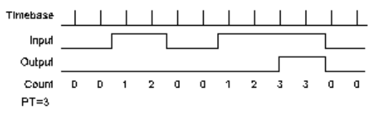
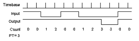
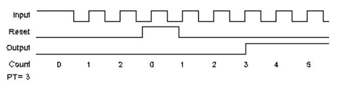
The counter will count on the positive transition of the input signal to the counter. When the count reaches the set value the output will then turn on.
Here is the timing chart for an up counter with a set value of 3.
Let’s look at an example. We will use the %S005 (system 1-sec pulse) as the input to the counter. This counter will count to 10 and then turn on an output. The counter can then be reset by hitting the F1_Key (%K01) on our HMI.
Here is the ladder diagram.
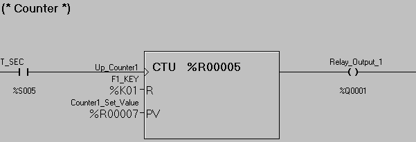
Note: The present count is in %R00005. This counter also uses %R00006 for internal use. The set value is taken from %R00007. Setpoints like the set value in %R00007 can be programmed when online with the controller. From the main menu select Program | Setpoints… This will allow you to set various registers in the PLC for your program.
We will now put both of these programs together along with some additional code so we can display this on our HMI built into the Horner XL4.
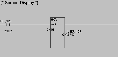
This ladder logic will ensure that screen number 2 will display when the program is first run. We use the first scan bit (%S001) to move the number 2 into the user screen register. (%R001)
This is all of the ladder program that is required for our application.
We will program in three screens.
Screen 2 – Title Screen
Screen 3 – Timer Screen
Screen 4 – Counter Screen
Screen 2 – Title Screen
Bitmaps can be loaded into the controller.
We have also included a screen jump object to jump to page 3 when selected.
Screen 3 – Timer Screen
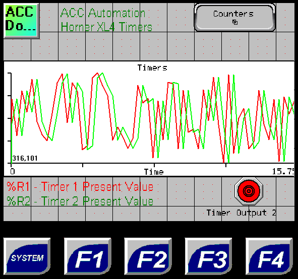
A screen jump object to jump to page 4 (Counters) has been programmed
Data trend has been programmed. Pen 1 is for Timer_1 and is red. Pen 2 is for Timer_2 and is green. An indicator is programmed for Timer Output 2.
Screen 4 – Counter Screen
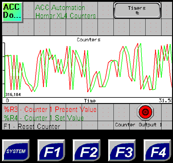
A screen jump object to jump to page 3 (Timers) has been programmed
Data trend has been programmed. Pen 1 is for Up_Counter1 and is red. Pen 2 is for Counter1_Set_Value and is green. An indicator is programmed for Relay Output 1.
You can download this application here. It will contain all of the screens and logic programming.
See this logic in action by watching the YouTube video below.
All of the documentation for the Horner XL4 can be downloaded at the following URL:
https://hornerautomation.eu/product/xl4-prime-ocs-3-5-colour-touchscreen/
Next time we will look at compare and move instructions.
Watch on YouTube: Horner XL4 Timers and Counters
If you have any questions or need further information please contact me.
Thank you,
Garry
If you’re like most of my readers, you’re committed to learning about technology. Numbering systems used in PLCs are not difficult to learn and understand. We will walk through the numbering systems used in PLCs. This includes Bits, Decimal, Hexadecimal, ASCII, and Floating Point.
To get this free article, subscribe to my free email newsletter.
Use the information to inform other people how numbering systems work. Sign up now.

The ‘Robust Data Logging for Free’ eBook is also available as a free download. The link is included when you subscribe to ACC Automation.