This post is a further follow-up from my original ‘Here’s a Quick Way to Understand PLC Inputs and Outputs.’ There are two different kinds of PLC outputs, Discrete and analog. Discrete outputs are either ‘ON’ or ‘OFF’; 1 or 0. You can think of them as a single light bulb. Analog outputs have a range to them. They are outputs that usually will control proportional valves, drive speeds, etc. They typically have one of the following signals outputted from the PLC: 4-20mA, 0-10VDC, 1-5VDC.
PLC Discrete Outputs – On / Off
The above diagram has three outputs—a coil, light, and motor. The Ladder outputs Y0, Y1, and Y2 control the outputs respectfully. You will notice that when the Ladder output turns on, the corresponding output card bit LED turns on. This will then energize the Output hardwired to the device.
The PLC logic is solved left to right, top to bottom in most PLCs. The outputs are turned on or off at the end of every PLC Scan. Physical outputs are not set/reset until an I/O refresh is performed at the end of every scan. This means that if I have a scan of 1 msec, the maximum time it will take to turn on/off the Output is 1 msec.
PLCs will sometimes have the ability to update the I/O in the middle of a scan. This can be used to update the I/O quickly, or control stepper drives for motors by giving them a pulse train output from the discrete PLC output. A pulse train is just a short series of on/off states of the Output. Please refer to your PLC manufacturer’s manual for this instruction.
PLC Analog Outputs – Range of Output
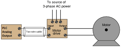
An analog output converts a digital value to a voltage or current level that can be used to control (vary) physical outputs. In the example above, we are controlling the speed of the motor. Words in the PLC will control the analog value.
Example:
4 – 20 mA current Output – 8-bit resolution
4 mA = 00000000 base 2 = 00 base 16
20 mA = 11111111 base 2 = FF base 16
For a review of numbering systems, follow the link below:
What Everybody Ought to Know About PLC (Programmable Logic Controller) Numbering Systems
In the industrial environment, noise from variable frequency drives, improper grounding, etc., can interfere with your analog input. The following post will show a quick method to reduce this noise.
The Secret Of Getting Rid Of Noise On Your Analog Signal
Previous Post:
How PLC Inputs Work
Watch on YouTube: How PLC Outputs Work
If you have any questions or need further information, please get in touch with me.
Thank you,
Garry
If you’re like most of my readers, you’re committed to learning about technology. Numbering systems used in PLCs are not challenging to learn and understand. We will walk through the numbering systems used in PLCs. This includes Bits, Decimals, Hexadecimal, ASCII, and Floating Points.
To get this free article, subscribe to my free email newsletter.
Use the information to inform other people how numbering systems work. Sign up now.

The ‘Robust Data Logging for Free’ eBook is also available as a free download. The link is included when you subscribe to ACC Automation.