Previously we used VB6 (Visual Basic 6) to implement the Omron Host Link Protocol to communicate to our programmable logic controller. (PLC) In part 2 we used Visual Basic for Applications (VBA) to accomplish our host link serial communication. We will now look at using VB.Net to establish and retrieve information in and out of the PLC using host link. (C mode commands)
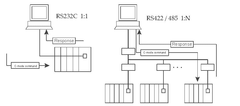
Hostlink communication protocol is a method developed by Omron for communication to PLC’s and other equipment. This ASCII based protocol is used over RS232 or RS422/RS485. It is a many to one implementation which means that you can communicate with up to 32 devices back to a master. (1:N) This communication on the industrial floor can control PLC’s, Temperature Controllers, Panel Meters, etc.
The Omron CP1H plc will be used with a CP1W-CIF11 (RS485) communication serial link adapter. We will also use a USB-485M Universal Serial Bus to RS485 adapter from automation direct. The video at the end of this post will demonstrate the communications by reading 10 registers from the DM area of the PLC.
Omron Host Link Hardware for VB.Net
Let’s look at the hardware that we will be using. The CP1W-CIF11 is a communication module that can fit into either port on the CP1H.
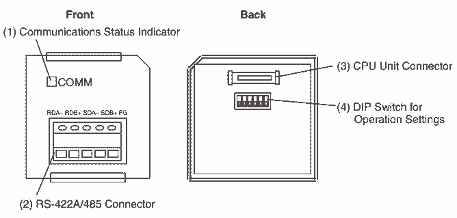
The terminal on the front is as follows:
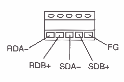
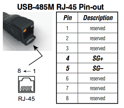
We will be using the RDA- and RDB+ terminal to hook up to our SG+ and SG- wires from our USB to RS485 converter.
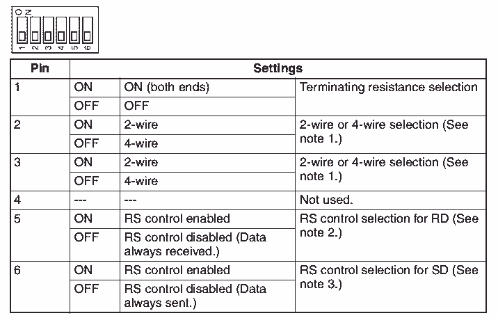
Set the following dip switches on the back of the CP1W-CIF11 for RS485 2-wire serial mode.
Pin 1 – Off
Pin 2 and 3 – On
Pin 4 – Not used (Off)
Pin 5 and 6 – On
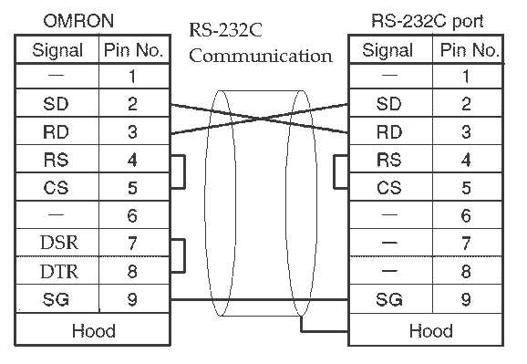
Note: If using an Omron 9 pin serial port, here is the diagram for the cable pinout. It will use only three wires and the handshaking signals will be jumped out. This is for an Omron 9 pin RS232C port such as a CP1W-CIF01, CQM1H, C20H, PT Terminals, etc. You can use this cable for programming or communication links.
Installing VB.net
We will be using Visual Studio Community (VB.net) for the software package to communicate to the CP1H PLC. You can download and install Visual Studio Community at the following URL:
https://www.visualstudio.com/downloads/
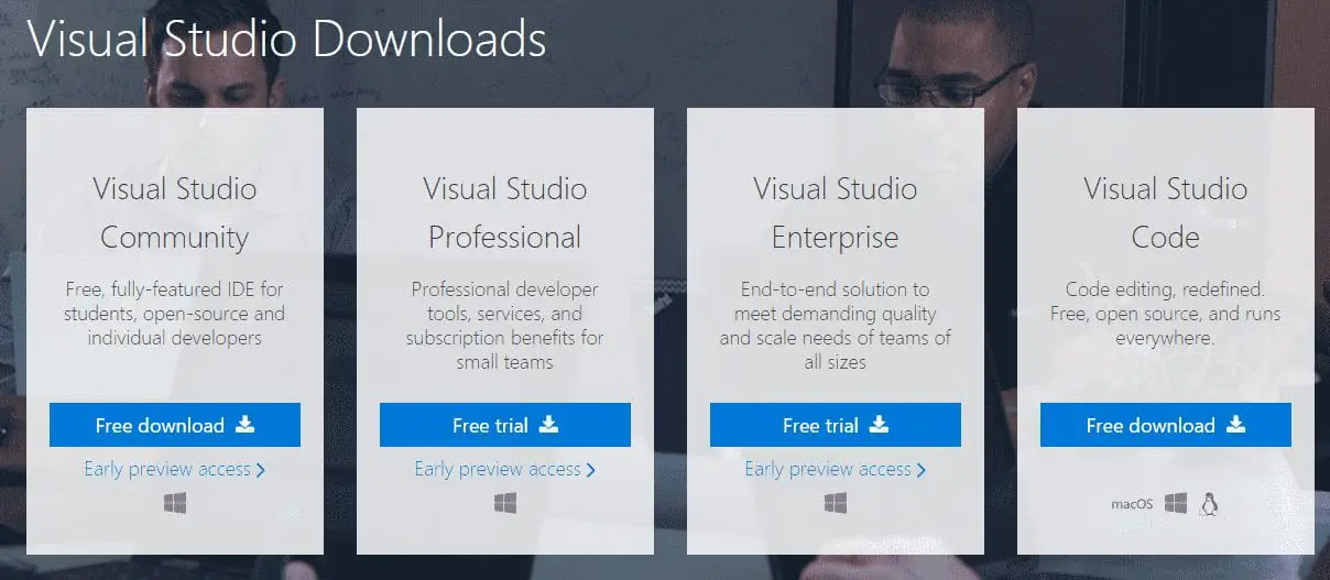
This is a free, fully-featured IDE (Integrated Development Environment) for students, open-source, and individual developers.
Omron Host Link Protocol Review
The Host Link Protocol (C-mode Commands) is a command/response system for serial communications. This will allow us to perform control operations between a CPU unit and a host computer directly connected to it.
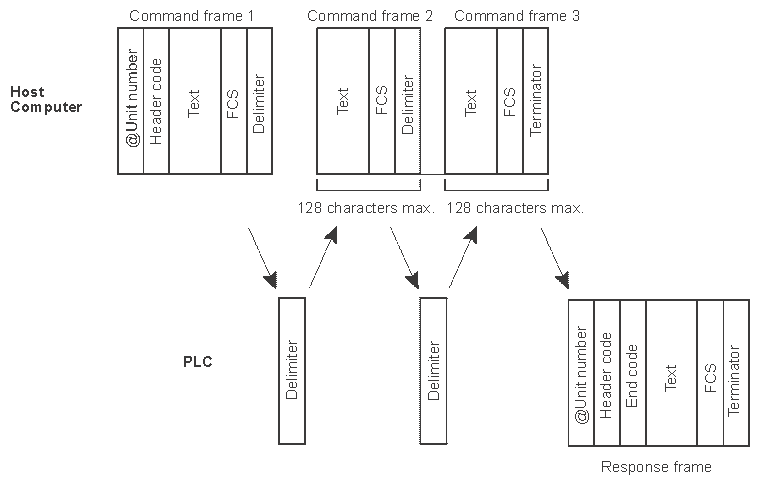
Here is the command format. This is what the computer will send to the PLC.

- @ – This indicates the start of the command
- Unit Number – This is set in BCD from 00 to 31. So the network can have 32 devices attached
- Header Code – This has two characters that specify what you want to do. Example “RD” is used to read the Data Memory area of the PLC.
- Text – This is the parameters associated with the header code. (Command Code)
- FCS – The frame check sequence (FCS) is a calculated 2 character value.
- Terminator – The “*” and Carriage Return (CHR$(13)) are used to indicate the end of the command.
Here is the response format. This is what the PLC will send back from the command.

- @ – This indicates the start of the response
- Unit Number – This is the device that is responding to the command sent. (00-31)
- Header Code – The same command code sent is returned.
- End Code – The error code of the command executed is returned. Example “00” no error code.
- Text – Returned only if data is being read.
- FCS – The frame check sequence (FCS) is a calculated 2 character value.
- Terminator – The “*” and Carriage Return (CHR$(13)) are used to indicate the end of the response.
Here is a diagram of the communications that will take place. If the response is greater than 131 characters, a delimiter is used ‘CR’ (CHR$(13)) instead of the terminator.
Host Link Protocol is usually embedded in a lot of the Omron product. Please refer to the specific communication manual for the command codes for temperature controllers, process controllers, and Omron PLC units.
Here is a chart of the Omron Manuals for PLC Host Link Operations.
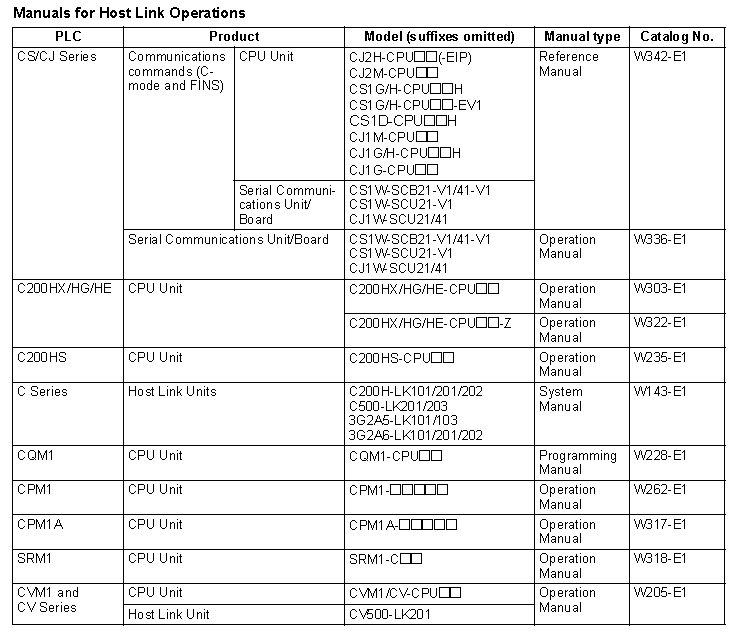
We will be using a CP1H Omron PLC. Here is the manual for the host link operations.
http://www.omronkft.hu/nostree/pdfs/plc/networks/w342-e1-15_cj-cs_communication.pdf
Here are the commands we can use with the CP1H.
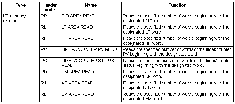
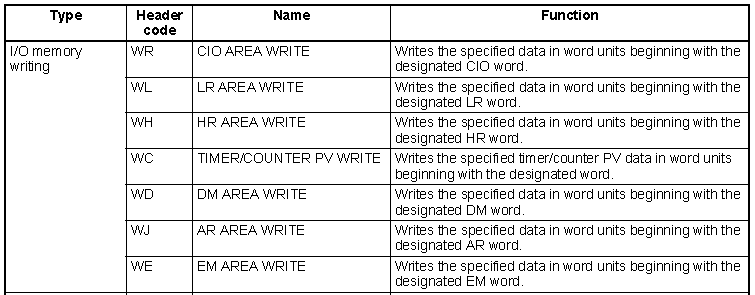
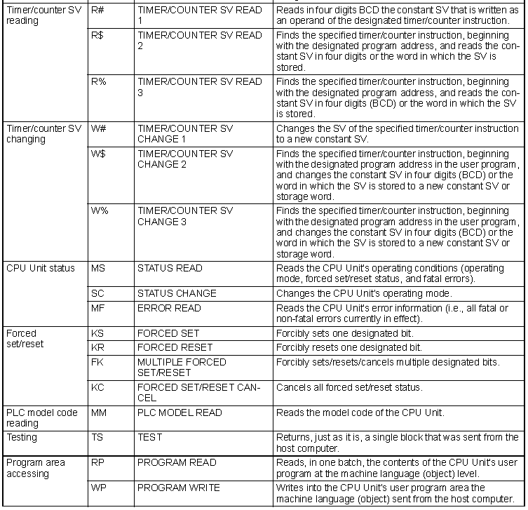

See the above manual for the instructions on using each of the commands.
Visual Basic Net (Example) – VB.Net
We will use the VB6 example and read the first 10 words from the DM area of the Omron PLC.
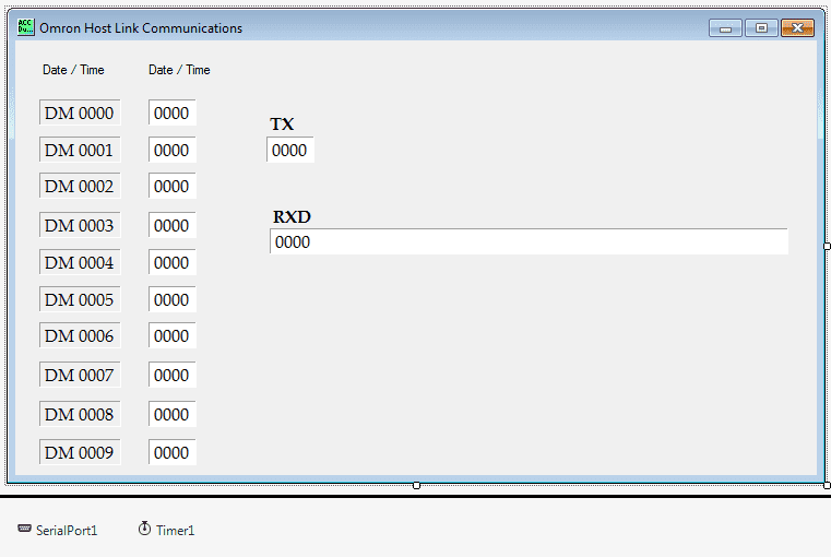
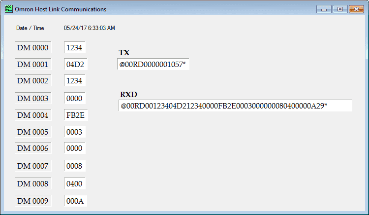
The first step is the design the form. You can see that we have our ten DM area words set out to populate with values. We also have a TX for transmitting. This will show what we are sending to the PLC. The RDX will show what the response will be from the PLC.
SerialPort is used to communicate through the serial ports of the computer. The following are the settings for the communication port.
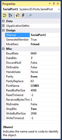
COM5, 9600, Even Parity, 7 Data Bits, and 2 Stop bits. These are the default values for Omron serial communication.
A timer is used for the communication timing. Every time the timer expires the communication will take place with the PLC.
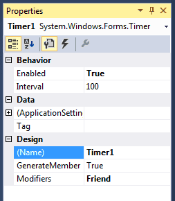
In our case, we will have a 100 msec delay between communication commands to the PLC.
Here is the code to create some public strings and handle the time function every 100 msec.
Public Class Form1
 Public TX As String
 Public FCS As String
 Public RXD As String

 Private Sub Timer1_Tick(sender As Object, e As EventArgs) Handles Timer1.Tick
 Timer1.Enabled = False
 'Display current date and time
 Label2.Text = System.DateTime.Now

 'Open the serial port
 If SerialPort1.IsOpen = False Then
 SerialPort1.Open()
 End If
 Dim charreturn As Integer

 'Check DM AREA DM0000 to DM0009 data update
 TX = "@00RD00000010"
 Call GetFCS()
 Label25.Text = TX + FCS + "*"
 Call communicate()
 SerialPort1.Close()

 ' Set information on the screen
 Label26.Text = RXD
 If RXD.Substring(5, 2) = "00" Then
 Label4.Text = RXD.Substring(7, 4)
 Label5.Text = RXD.Substring(11, 4)
 Label7.Text = RXD.Substring(15, 4)
 Label9.Text = RXD.Substring(19, 4)
 Label11.Text = RXD.Substring(23, 4)
 Label13.Text = RXD.Substring(27, 4)
 Label15.Text = RXD.Substring(31, 4)
 Label17.Text = RXD.Substring(35, 4)
 Label19.Text = RXD.Substring(39, 4)
 Label21.Text = RXD.Substring(43, 4)
 End If

 Timer1.Enabled = True
 End Sub
This is the code for the FCS calculation.
Private Sub GetFCS()
 'This will calculate the FCS value for the communications
 Dim L As Integer
 Dim A As String
 Dim TJ As String
 L = Len(TX)
 A = 0
 For J = 1 To L
 TJ = Mid$(TX, J, 1)
 A = Asc(TJ) Xor A
 Next J
 FCS = Hex$(A)
 If Len(FCS) = 1 Then FCS = "0" + FCS
 End Sub
Here is the code to actually send and receive the information from the Omron CP1H PLC.
Note: Once information is sent on the port, we delay for 50 msec. This is more for the computer wait time. It can be 0 if nothing else is using computer ports. 50 works well when we are running CX-Programmer (USB Serial) and our VB.Net application (COM5).
Private Sub communicate()
 'This will communicate to the Omron PLC
 Dim BufferTX As String
 Dim fcs_rxd As String
 Try
 RXD = ""
 BufferTX = TX + FCS + "*" + Chr(13)

 'Send the information out the serial port
 SerialPort1.Write(BufferTX)

 'Sleep for 50 msec so the information can be sent on the port
 System.Threading.Thread.Sleep(50)

 'Set the timeout for the serial port at 100 msec
 SerialPort1.ReadTimeout = 100

 'Read up to the carriage return
 RXD = (SerialPort1.ReadTo(Chr(13)))

 Catch ex As Exception
 'If an error occurs then indicate communication error
 RXD = "Communication Error"
 End Try

 'Get the FCS of the returned information
 fcs_rxd = RXD.Substring(RXD.Length - 3, 2)
 If RXD.Substring(0, 1) = "@" Then
 TX = RXD.Substring(0, RXD.Length - 3)
 ElseIf RXD.Substring(2, 1) = "@" Then
 TX = RXD.Substring(2, RXD.Length - 5)
 RXD = RXD.Substring(2, RXD.Length - 1)
 End If

 'Check the FCS of the return information. If they are not the same then an error has occurred.
 Call GetFCS()
 If FCS <> fcs_rxd Then
 RXD = "Communication Error"
 End If
 End Sub
 End Class
You can download this program as well as the source code here.
Watch on YouTube: Implementing the Omron Host Link Protocol VB Net
If you have any questions or need further information please contact me.
Thank you,
Garry
If you’re like most of my readers, you’re committed to learning about technology. Numbering systems used in PLC’s are not difficult to learn and understand. We will walk through the numbering systems used in PLCs. This includes Bits, Decimal, Hexadecimal, ASCII and Floating Point.
To get this free article, subscribe to my free email newsletter.
Use the information to inform other people how numbering systems work. Sign up now.
The ‘Robust Data Logging for Free’ eBook is also available as a free download. The link is included when you subscribe to ACC Automation.

