We will now create our first program on the Productivity Mini PLC P1-M622-16DR. Last time we connected the Mini PLC with our computer running the Productivity Suite Software. An Ethernet (RJ45) connection was established to our programmable logic controller. We will now create our first program for our Productivity Mini PLC. Our program will be a simple start-stop circuit for a motor. Here is a post that will explain the logic behind our program circuit. https://accautomation.ca/how-to-make-a-start-stop-jog-circuit-in-a-plc/
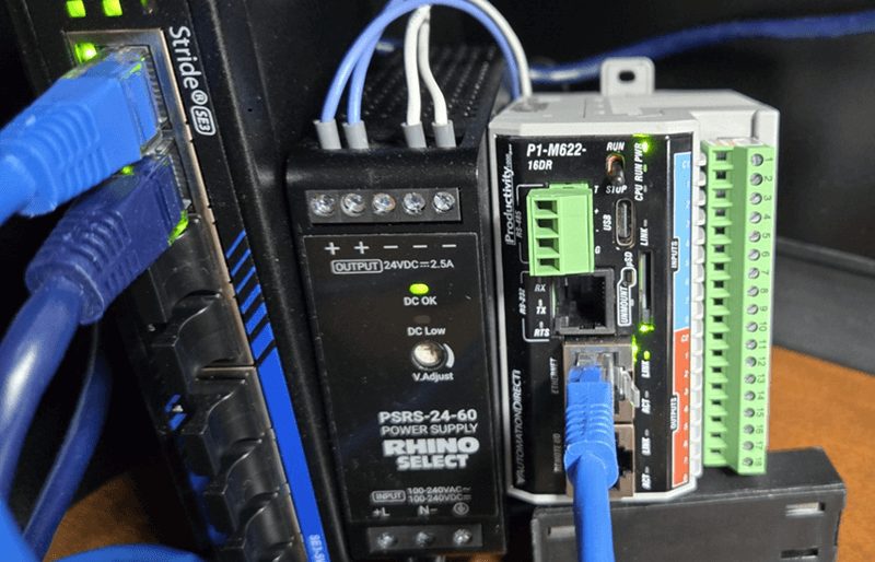
The P1-M622-16DR features 8 built-in 24VDC sinking inputs and 8 relay outputs—everything you need for this first program right in the compact CPU itself.
Let’s get started.
Previously in this Productivity Mini PLC series, we have discussed:
P1-M622-16DR Mini PLC System Hardware – Video
Installing the Software – Video
Establishing Communication – Video
First Program – Video
Monitoring and Testing the Program – Video
Wiring and Testing – Video
Online Editing and Fail-Safe Wiring – Video
Start a New Project – Mini PLC First Program
Start the Productivity Suite programming software from the desktop icon or the Windows Start menu. (All Programs | AutomationDirect | Productivity Suite | Productivity Suite)
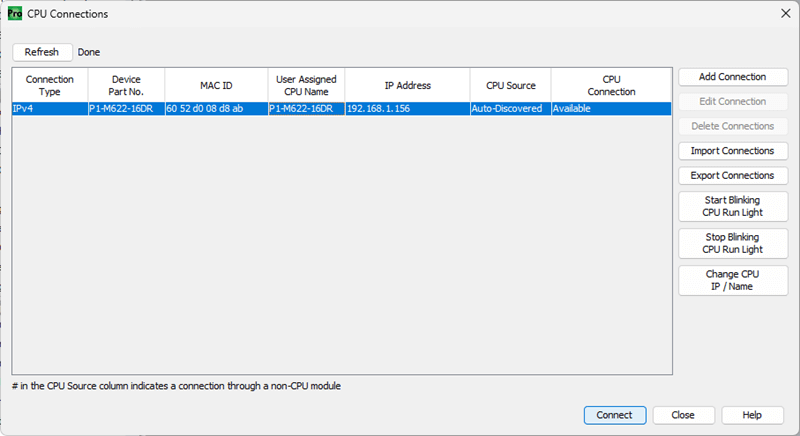
Our Start Productivity window will now appear. Select “Read the Project from the CPU”. As before, it will present the options for our communication. (Ethernet)
We will select our Ethernet connection to the PLC. This will give us a warning because we currently do not have a program in the PLC. Select Connect.
We will receive error messages because there is currently no program in the CPU of our Productivity P1 Mini. Select OK to acknowledge the error messages.
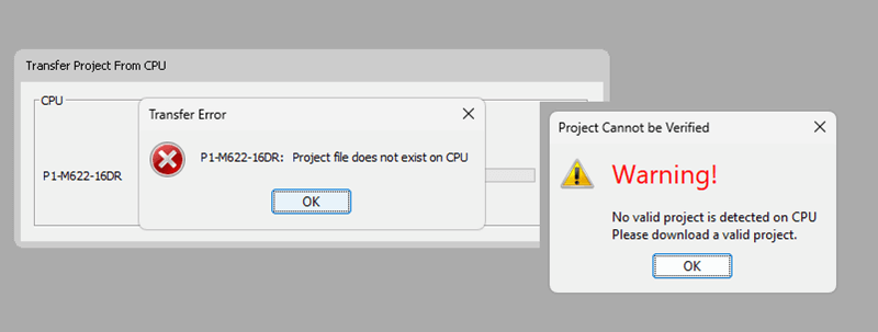
We are now connected to our PLC.
Choose CPU – Mini PLC First Program
Select the New Project icon on the menu options at the top of the screen.
You can also use the main menu and select New Project. (File | New Project)
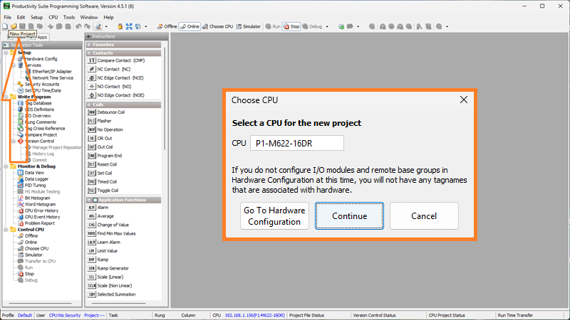
The Choose CPU window will now appear. This will allow us to select the hardware for our automation project.
Select P1-M622-16DR. This is our Productivity Mini PLC with 8 DC inputs and 8 relay outputs.
Select “Continue”
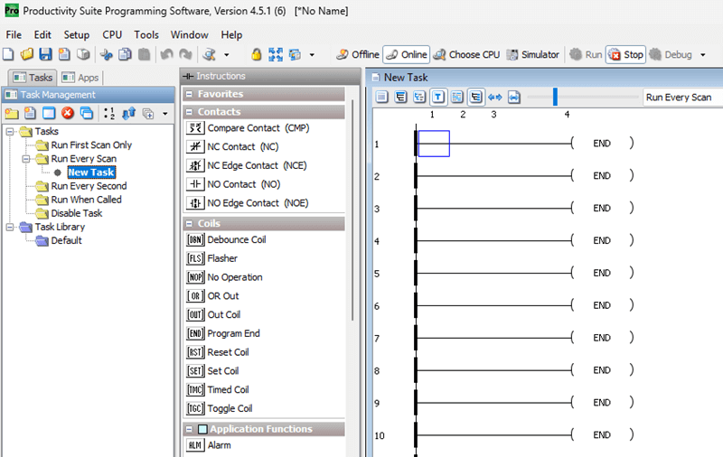
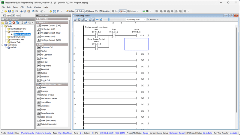
A New Task program will now appear under the Tasks heading in the Run Every Scan folder. This is located in the Task Management. The New Task is automatically displayed and currently shows as a series of END statements.
Tag Database – Mini PLC First Program
We reference our physical inputs and outputs through our tag database. This is automatically done when we configure our hardware. Default names were generated and given to the integrated I/O points.
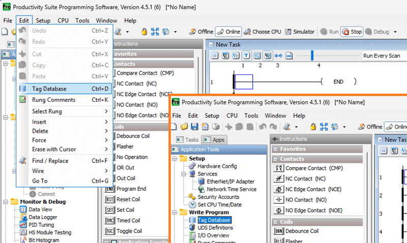
Select “Tag Database” under the Write Program heading in the Application Tools. Alternatively, you can use the main menu | Edit | Tag Database selection.
The tag database will show us a list of all of the assigned bits in the CPU. These assigned areas can be automatic or manually generated. To view the physical inputs and outputs we assigned when configuring the system, scroll through all the tags. Another way is to select only “Discrete Inputs” and “Discrete Outputs” to display.
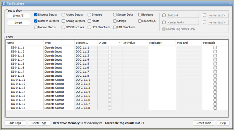
We will now only see our system’s inputs and outputs. For the P1-M622-16DR Mini PLC, the automatic assignment can be read as follows:
DO-0.1.1.1 – Discrete Output – System 0 – Base 1 – Slot 1 – Bit location 1
So the first input on our Mini PLC would be: DI-0.0.0.1 – Discrete Input – System 0 – Base 1 – Slot 1 – Bit location 1
The P1-M622-16DR has inputs DI-0.1.1.1 through DI-0.1.1.8 and outputs DO-0.1.1.1 through DO-0.1.1.8.
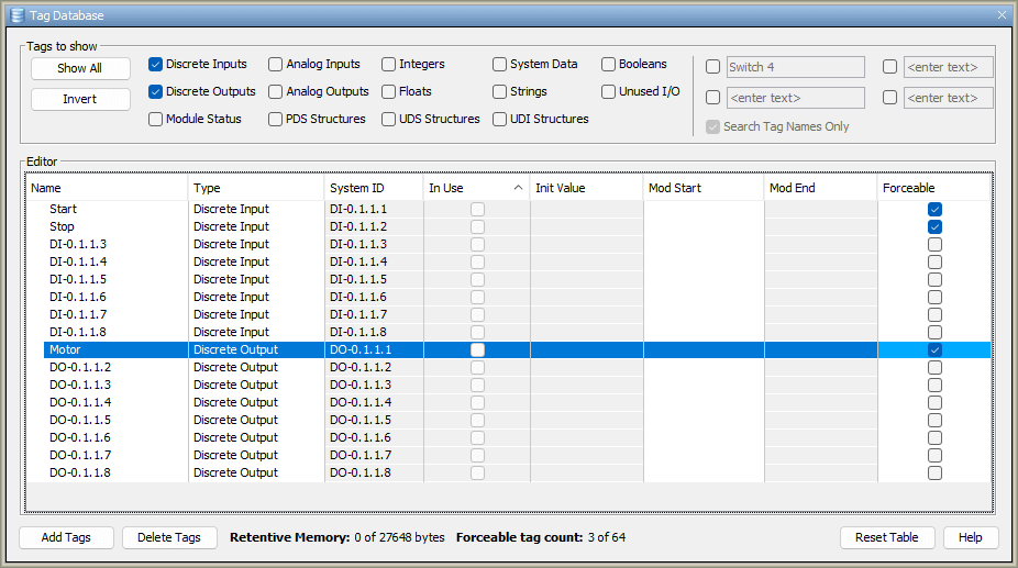
Under the Editor in the Tag Database, you will see several different columns. The first one is “Name”. Double-clicking the current default name lets you enter a new one. We will name the first two inputs as “Start” and “Stop”. The first output will be named “Motor”.
The In Use column indicates whether this tag is used in your program or tasks.
The Forceable selection for the tag determines whether we can manually turn this input or output on or off in the productivity programming software. We will make all three of our named tags forceable so that we can test our logic from within the software, without physically wiring the inputs and outputs.
Select the X in the top right corner to close the Tag Database window.
Creating the Ladder Logic – Task
All ladder logic is organized into groups called tasks. You can have several tasks to help you break up and organize your program.
In the Productivity Suite software, you will notice the Task Management window. This is where you can name, organize, and add new tasks to your program.
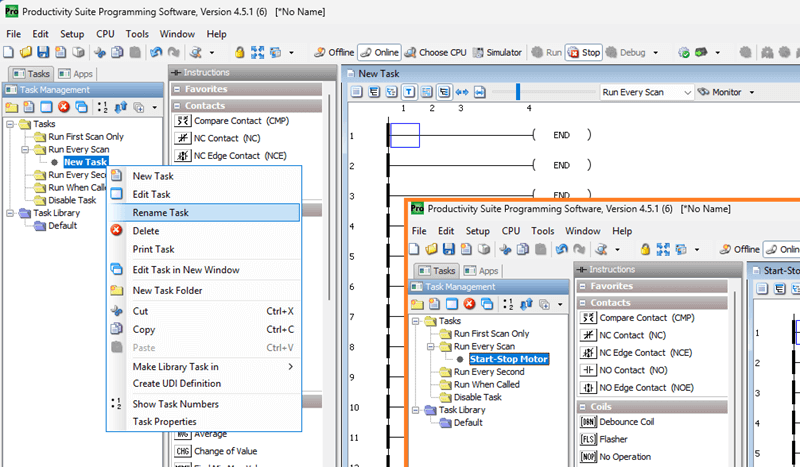
The new task will be set to “Run Every Scan” by default. This is where we will be creating our first program.
In Task Management, move your cursor over the New Task and right-click. Select Rename Task. We will rename this task “Start-Stop Motor”.
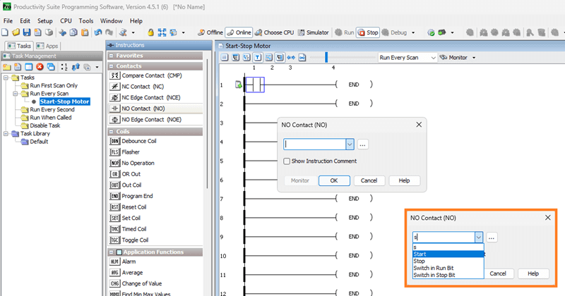
Place your cursor on the top left side of the first rung in the new task window, now named Start-Stop Motor. Double-click on the NO Contact under the instructions on the right side.
We will select our first input on the Mini PLC. DI-0.1.1.1. This was named Start in our tag database. As you enter the name of the tag, all of the tag names that are similar will be displayed. Select the Start tag.
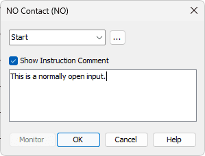
The show instruction comment will allow you to write comments documenting information about the location of the instruction in the rung.
Select OK to place this instruction in the rung.
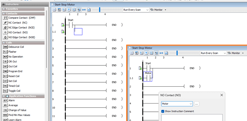
With the cursor next to the instruction we just inserted, draw a vertical line down. We can use the keyboard combination of Ctrl + Down arrow, or from the main menu select Edit | Wire | Down.
Move the cursor manually under the previous contact.
Double-click on a NO Contact.
Enter the motor tag, which is the DO-0.1.1.1 address. This will be our sealing contact for the start input.
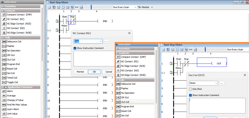
Put a normally closed contact (NC) next to the previous ones.
Enter the tag “Stop” at address DI-0.1.1.2. This will be our STOP contact for our circuit. This would be wired as normally open, since we are using normally closed in our ladder logic.
Move the cursor to the end of the rung. Under the coils heading in the instructions, double-click Out Coil.
Enter the tag “Motor” at address DO-0.1.1.1. This is the same output address that we used for our sealing contact. This will actually turn on our first relay output on the Mini PLC. The One Shot checkbox is available to enable output for only one scan. See the following post for an explanation of a one-shot. https://accautomation.ca/how-to-make-a-one-shot-in-the-plc/
Select OK to finish our rung.
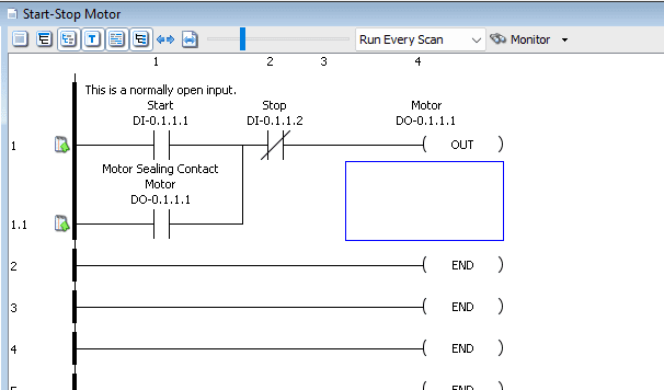
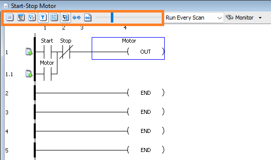
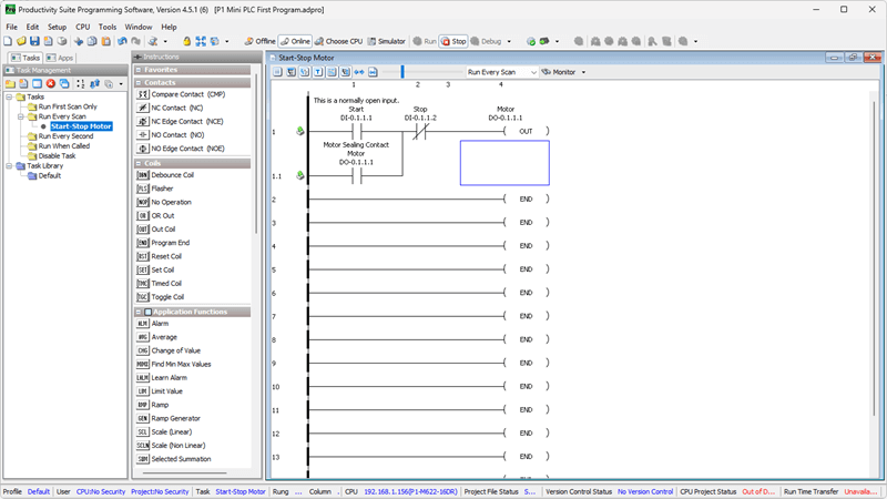
Our completed start-stop circuit should look like this:
    DI-0.1.1.1      DI-0.1.1.2      DO-0.1.1.1
   ----] [----+----]/[-------------( )----
      START   |     STOP           MOTOR
              |
   ----] [----+
   DO-0.1.1.1
    (SEAL)
Selecting the Tag Details icon displays the physical address and tag information. The instruction comment shows the comments entered for the instruction’s location.
Saving the Program – Mini PLC First Program
The symbols next to our rung mean that the program has not been saved. Select the Save icon in the top menu, or choose File | Save Project from the main menu.
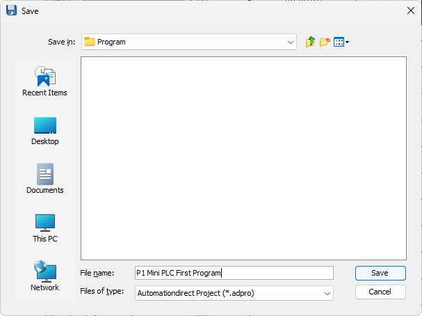
You will be asked for a name and location for the saved project.
Notice that the information at the bottom of the window now indicates that the project has been saved. The project name is also displayed at the top of the window. In our case, the name is P1 Mini PLC First Program.adpro.
Transfer Project to CPU
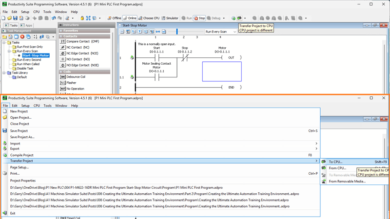
We will now transfer our project to the CPU. Select the transfer project to CPU icon in the top menu. You can also select File | Transfer Project | to CPU from the main menu.
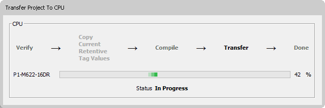
Our program will then compile and transfer to the PLC.
Watch the video below to see how easy it is to create a program in our Productivity Mini PLC P1-M622-16DR.
Productivity Mini PLC P1-M622-16DR from AutomationDirect
Overview Link (Additional Information on the Unit) Configuration (Configure and purchase a system – BOM) User Manual and Inserts (Installation and Setup Guides) Productivity Suite Programming Software (Free Download Link)
This software includes all instruction sets and help files for the Productivity Series.
Next time, we will look at running and monitoring our program in the Productivity Mini PLC P1-M622-16DR.
The Productivity Mini PLC series from AutomationDirect, and specifically, the P1-M622-16DR, is a compact powerhouse that packs serious capability into a surprisingly small footprint. To learn more, click here. Click here to build digital twins of 3D virtual machinery, test control logic, and learn automation without expensive hardware, using Machine Simulator.
Watch on YouTube: P1-M622-16DR Mini PLC First Program: Start-Stop Motor Circuit!
If you have any questions or need further information, please contact me. Thank you, Garry
Related Posts:
- How to Make a Start Stop Jog Circuit in a PLC
- How to Make a One Shot in the PLC
- Master PLC Programming: Create a Start-Stop Motor Circuit Now!
There are many different PLC manufacturers with other hardware and software. All of the programmable logic controllers have similar basic features. Here is how I would approach learning about basic PLCs.
Once you are familiar with the basics of the PLC, you will then learn specifics for the controller you will be programming.
This is the easiest way to learn about PLC programming.
Here are the controllers that we have covered or are covering at ACC Automation:
LS Electric XGB PLC Series
BRX Do-More Series (Do-More Designer Software + Simulator)
Productivity Series P1000 / P2000
Click PLC Series
Omron CP1H Series
Horner XL4 PLC Series
Arduino Opta PLC
The EasyPLC Software Suite is a comprehensive package that includes PLC, HMI, and machine simulator software. This allows you to make a digital twin. See below to receive 10% off this software. This PLC learning package contains the following:
Easy PLC – PLC Simulation will allow programming in Ladder, Grafcet, Logic Blocks, or Script.
HMI System – Easily create a visual human-machine interface (HMI)
Machine Simulator – A virtual 3D world with real-time graphics and physical properties. PLC programs can be tested using the EasyPLC or through other interfaces. (Modbus RTU, TCP, etc.)
Machine Simulator Lite – Designed to run on Android Devices.
Machine Simulator VR – Virtual Reality comes to life so you can test, train, or practice your PLC programming.
Purchase your copy of this learning digital twin package for less than $95 USD for a single computer installation or less than $110 USD to allow access on multiple computers.
Receive 10% off the investment by typing in ACC in the comment section when you order.
Learn PLC programming the easy way. Invest in yourself today.
Examples of PLC program development using the five steps.
Click PLC – Easy Transfer Line Programming – Video
Productivity PLC Simulator – Chain Conveyor MS – Video
Five Steps to PLC Program Development – Die Stamping
PLC Programming Example – Process Mixer
PLC Programming Example – Shift Register (Conveyor Reject)
PLC Programming Example – Paint Spraying
PLC Programming Example – Delay Starting of 7 Motors
PLC Programming Example – Pick and Place
PLC Programming Example – Sorting Station (Shift Register)
PLC Programming Example – Palletizer
If you’re like most of my readers, you’re committed to learning about technology. The numbering systems used in PLCs are not difficult to understand. We will walk through the numbering systems used in PLCs. This includes Bits, Decimals, Hexadecimal, ASCII, and Floating Points.
To get this free article, subscribe to my free email newsletter.
Use the information to educate others on how numbering systems work. Sign up now.

The ‘Robust Data Logging for Free’ eBook is also available as a free download. The link is included when you subscribe to ACC Automation.