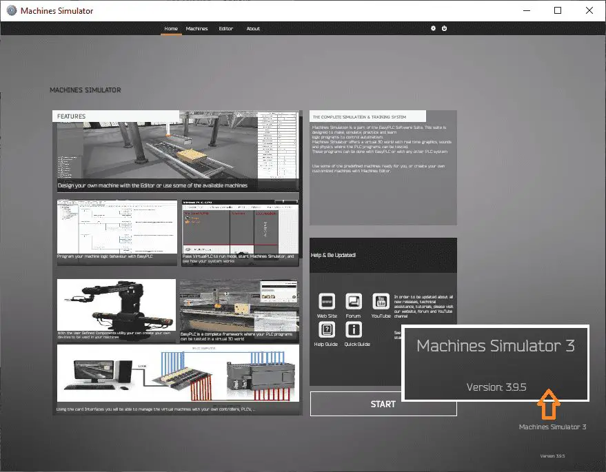
EasyPLC Software Suite is a complete PLC, HMI, and Machine Simulator Software package. This PLC learning package includes a Machine Simulator (MS). This virtual 3D world with real-time graphics and physical properties can communicate to several different programmable logic controllers. (PLC)
 We will be developing a Click PLC program for a transfer line. This is just one of the prebuilt machines in the simulator to learn PLC programming. We will be developing the ladder logic, connecting via Modbus RTU, and testing our program. This will be done using the five steps to PLC program development. Let’s get started!
Previously we have done the following:
Easy PLC Installing the Software – Video
Machine Simulation – EasyPLC Software Suite
The Machine Simulator (MS) in the EasyPLC software suite helps you in the development of your PLC control system. This 3D world will allow you to develop your control program and test prior to using it in the physical world. There are several different machine builds that you can connect to and learn to program easily. We will be using the Easy Transfer Line in the machine simulator connected to a Click PLUS PLC.
Easy Transfer Line – Program Development
We will now apply these five steps to the easy transfer line in the machine simulator.
Developing the PLC program is a process that can be clearly defined. The five steps along with some practical examples are demonstrated in the following post examples:
Five Steps to PLC Program Development and PLC Programming
- Stamping Press
- Process Mixer
- Shift Register (Conveyor Reject)
- Paint Spraying
- Delay Starting of 7 Motors
- Pick and Place
- Sorting Station (Shift Register)
- Palletizer
Define the task: (Step 1 – Easy Transfer Line)
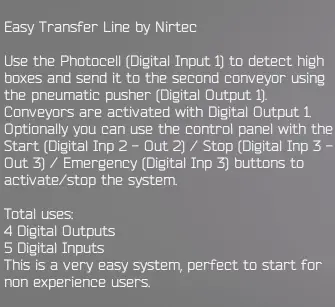
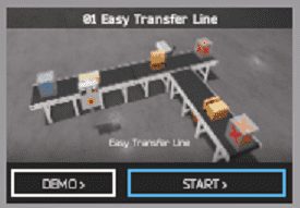
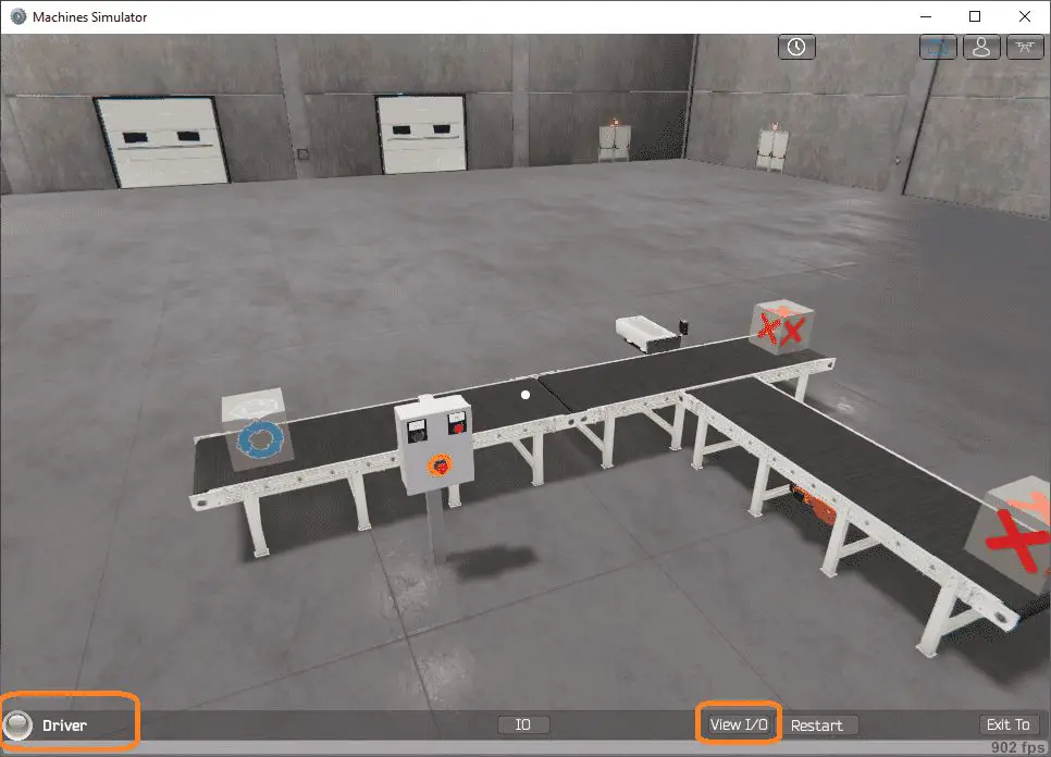
The machine simulator has a demo mode for the built-in machines. This will allow you to watch the operation of the easy transfer line. This will help you see what has to be done.
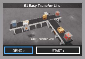 There is also a written version of the sequence on the left-hand side of the machine.
 The photocell is used to detect high boxes and send them to the second conveyor using the pneumatic pusher. Conveyors are activated with digital output 1. We will also include the control panel. The green start light will be on when the system is ready to run. When the start is pressed the stoplight will be on to indicate this is how the system is stopped. Pressing the emergency stop button will turn off both lights and stop the sequence.
 Watch the sequence of operation video below.
Define the Inputs and Outputs: (Step 2 – Easy Transfer Line)
The written version shown above specifies that we will require 4 digital outputs and 5 digital inputs for our easy transfer line.
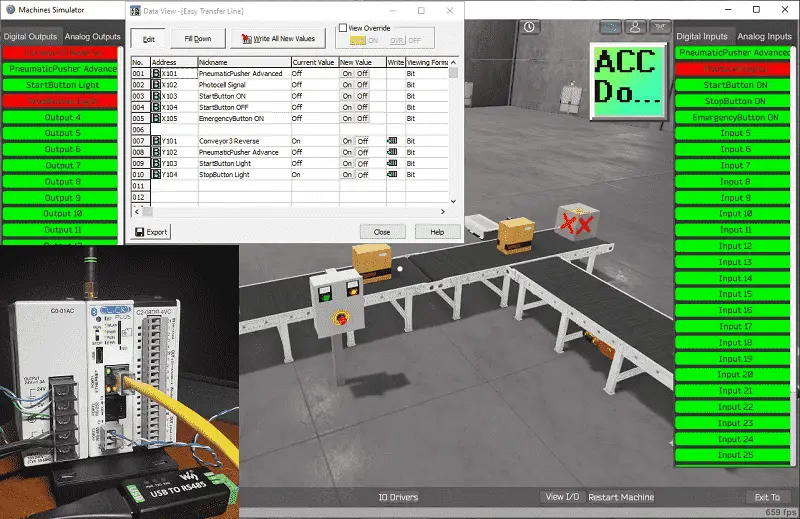
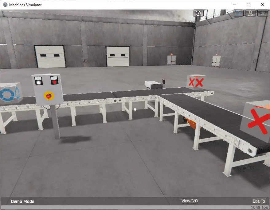
 While still in the demo mode of the machine simulator we can select the View IO on the bottom menu.
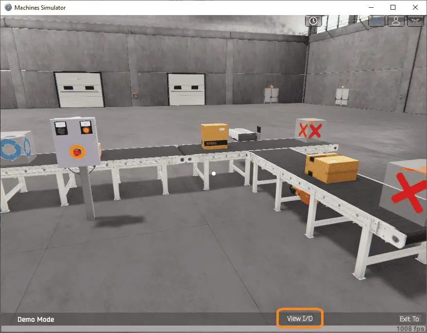
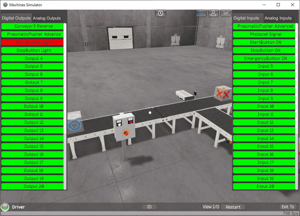
 This will now show the digital outputs on the left-hand side of the screen and the digital inputs on the right-hand side of the screen.
The machine simulator will be communicating to a Click PLC. Communication will be done with Modbus.
Using the Click PLC Software we can look at the address picker to determine the Modbus Addresses that we require for the program.
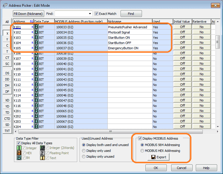
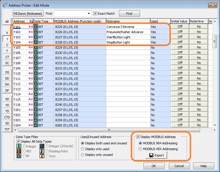 The following table will define the inputs and outputs (IO) and Modbus addresses in the Click PLC that we will use for this program.
| Digital Type | Description | Click Modbus Address | Machine Simulator Modbus Address |
| Y101 – Output | Conveyor | 8225 | 8224 |
| Y102 – Output | Pneumatic Pusher | 8226 | 8225 |
| Y103 – Output | Start PB Light | 8227 | 8226 |
| Y104 – Output | Stop PB Light | 8228 | 8227 |
| X101 – Input | Pneumatic Cylinder Extended | 100033 | 32 |
| X102 – Input | Photocell | 100034 | 33 |
| X103 – Input | Start PB | 100035 | 34 |
| X104 – Input | Stop PB | 100036 | 35 |
| X105 – Input | Emergency Stop | 100037 | 36 |
Note: The machine simulator will be offset by one on the Modbus Addresses.
Develop a logical sequence of operation: (Step 3 – Easy Transfer Line)
A flow chart or sequence table is used to fully understand the process the needs to be controlled. It must also answer questions like the following:
What happens when electrical power and/or pneumatic air is lost? What happens when the input/output devices fail? Do we need redundancy?
This step is where you can save yourself a lot of work by understanding everything about the operation. It will help prevent you from continuously re-writing the PLC program logic. Knowing all of these answers upfront is vital in the development of the PLC program.
Here is the sequence table for the easy transfer line.
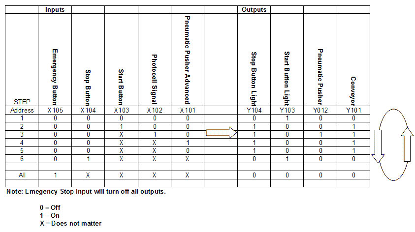 You read the input conditions and then look to the right-hand side for the outputs that will be set. The following line will then look for the input conditions again.
Develop the PLC program: (Step 4 – Easy Transfer Line)
Writing the ladder logic code for the PLC example will be the next step in our program development.
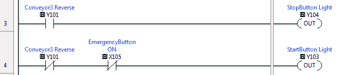
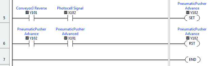
Starting and stopping the conveyor is done with a set and reset instruction.
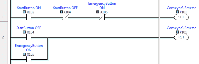 When the emergency stop is activated, both lights are off. This is an indication to the operator that the emergency stop has to be reset.
 When the photocell sees the high boxes, this activates the pneumatic pusher. When the pusher reaches the extended position, it will reset the pneumatic pusher.
Test the program: (Step 5 – Easy Transfer Line)
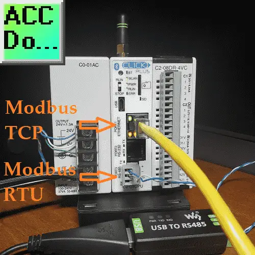
We will be using Modbus RTU on our Click PLC to communicate to the machine simulator.
 In the Click programming software, select COM Port Setup.
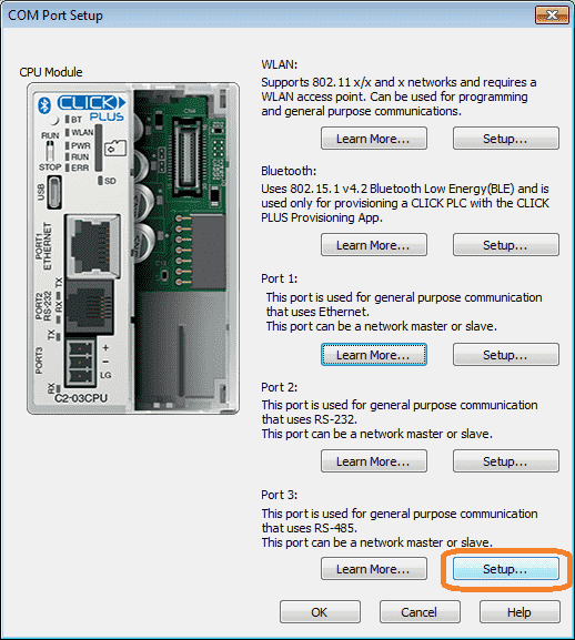 Select setup under Port 3.
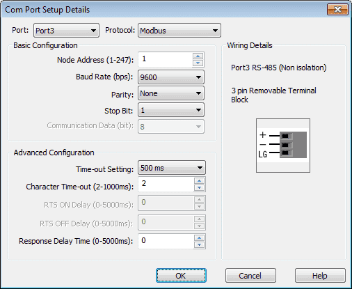 Our protocol is set for Modbus. The node address is 1 and the communication parameters are 9600, N, 8, 1. These parameters must match the settings in the machine simulator Modbus driver.
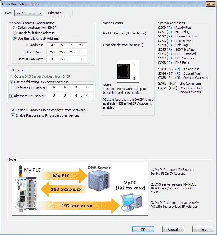 Port 1 is for Ethernet. Here we can set the IP address required. In our case, we will use this as the communication port for our Click Programming Software.
Call up the Easy Transfer Line in start mode.
 The status of the machine simulator will be along the bottom of the screen. Currently, we have no PLC connected.
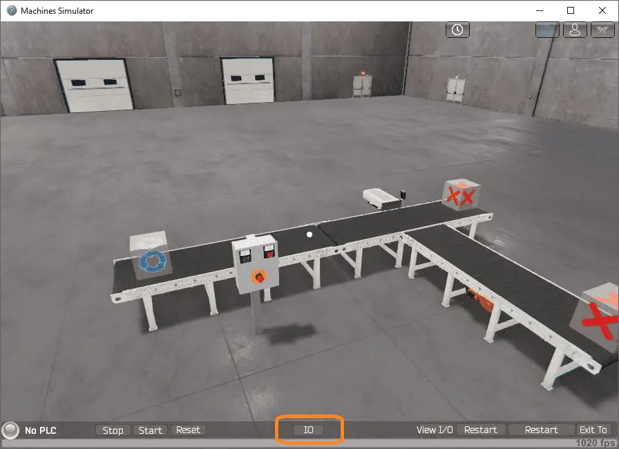 Select IO on the bottom middle of the screen.
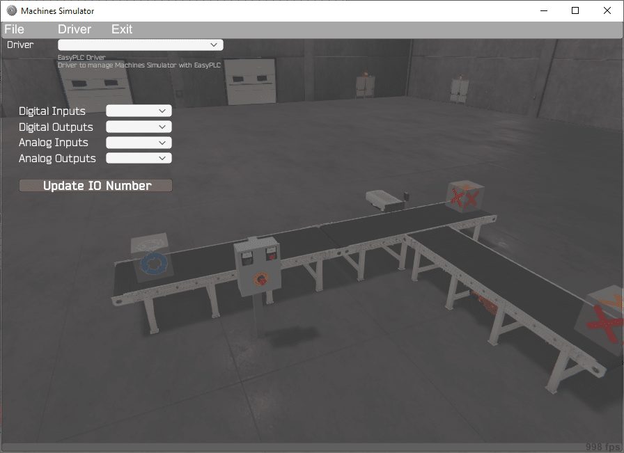 Under the driver pull-down menu, select “ModBusDriver”.
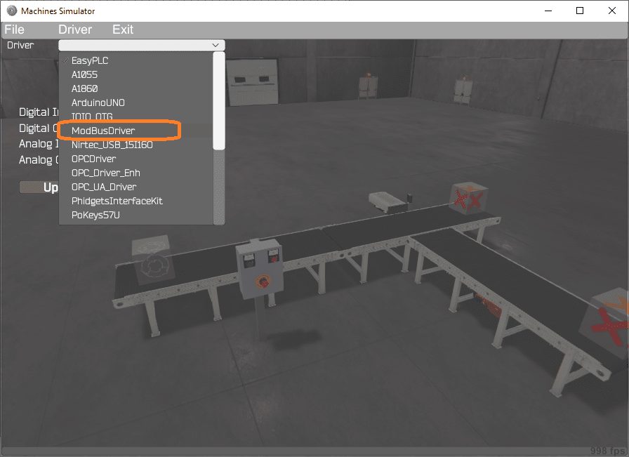 This driver will communicate Modbus TCP (Ethernet) and Modbus RTU (Serial).
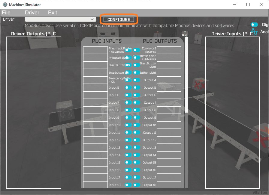 Select the configure button.
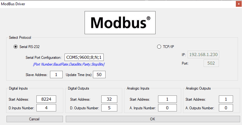 We can now enter the information for our Modbus driver. Select Serial RS232. This really means the serial port on the computer that will communicate to the PLC. We are using a USB to RS485 converter. This has been installed and operating on port COM 5.
The digital inputs from MS to the Click PLC will be Y101 to Y104. This will start at address 8224 due to the offset of 1. Digital outputs from MS to the Click PLC will be X101 to X105. This will start at address 32 due to the offset of 1.
Select the OK button.
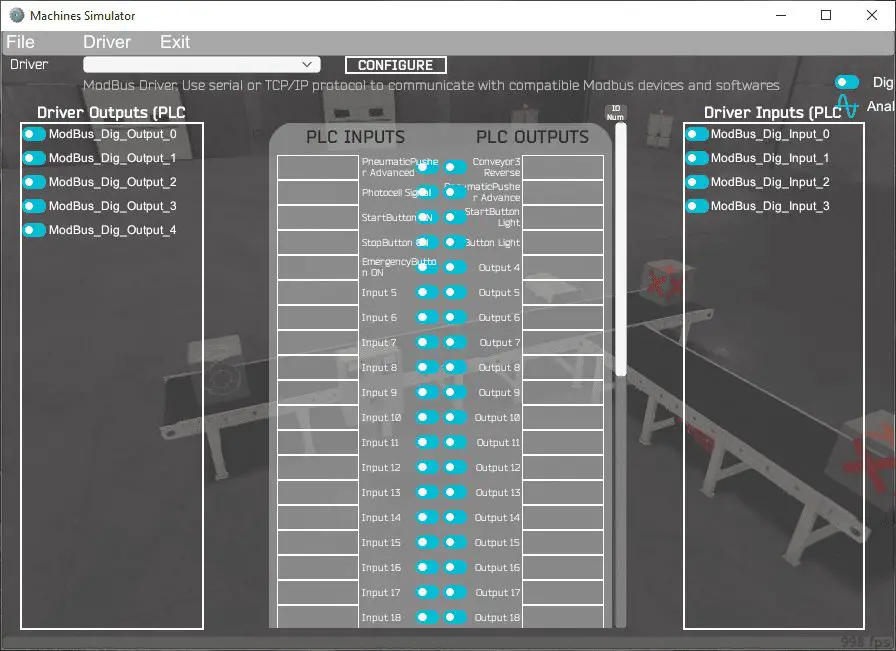 You will now see the inputs and outputs that we have specified for the Modbus driver. We can now manually assign the driver outputs to the PLC inputs and the driver inputs to the PLC outputs.
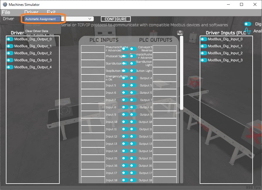 Select Automatic Assignment from the driver option in the main menu.
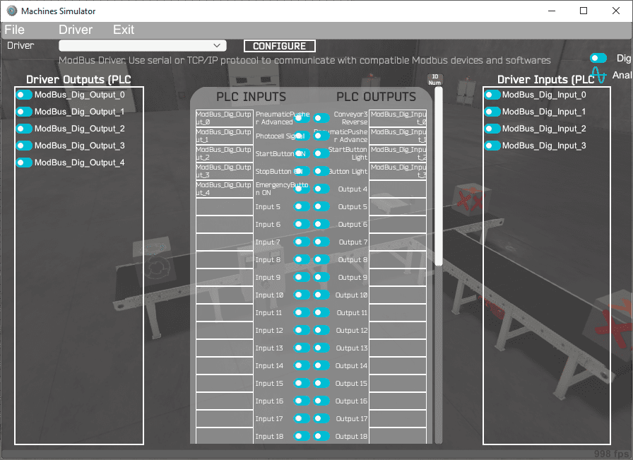 This will automatically assign the PLC IO to the Machine Simulator IO.
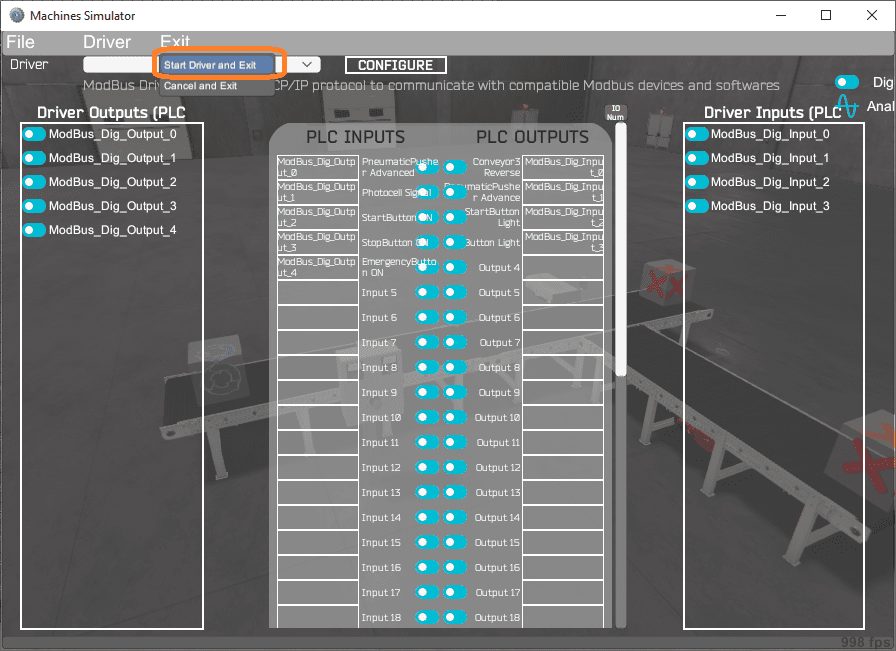 Select start driver and exit from the main menu.
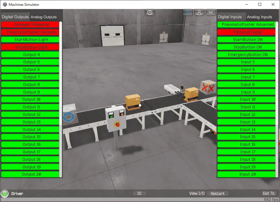
 You will see on the bottom left side of the window that the driver is operating. Select view IO to see the input and output status of the machine simulator.
 Ensure that the PLC is in run mode. We can now operate the machine simulator through the control panel.
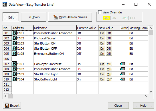
 Using the Data View window of the Click programming software we can also watch the inputs and output operations.
 Using Machine Simulator (MS) to test the program will ensure that our program works.
Machine simulator has a time frame that you can speed up or slow down the process to help you troubleshoot. Watch the video below to see this operation.
Download the Click PLC sample program and sequence chart for the Easy Transfer Line.
Watch the video below to see the five steps of program development applied to the transfer line. The machine simulator is one of the best applications to help you learn PLC programming.
EasyPLC Software Suite is a complete PLC, HMI, and Machine Simulator Software package. This PLC learning package includes the following:
Easy PLC – PLC Simulation that will allow programming in Ladder, Grafcet, Logic Blocks, or Script.
HMI System – Easily create a visual human-machine interface (HMI)
Machine Simulator – A virtual 3D world with real-time graphics and physical properties. PLC programs can be tested using the EasyPLC or through other interfaces. (Modbus RTU, TCP, etc.)
Machine Simulator Lite – Designed to run on Android Devices.
Machine Simulator VR – Virtual Reality comes to life so you can test, train or practice your PLC programming.
Purchase your copy of this learning package for less than $75 USD for a single computer install, or less than $100 USD to allow different computers.
Receive 10% off the price by typing in ACC in the comment section when you order. http://www.nirtec.com/index.php/purchase-price/
Learn PLC programming the easy way. Invest in yourself today.
Watch on YouTube: Click PLC – Easy Transfer Line Programming
If you have any questions or need further information please contact me.
Thank you,
Garry
If you’re like most of my readers, you’re committed to learning about technology. Numbering systems used in PLCs are not difficult to learn and understand. We will walk through the numbering systems used in PLCs. This includes Bits, Decimal, Hexadecimal, ASCII, and Floating Point.
To get this free article, subscribe to my free email newsletter.
Use the information to inform other people how numbering systems work. Sign up now.

The ‘Robust Data Logging for Free’ eBook is also available as a free download. The link is included when you subscribe to ACC Automation.