Learn PLC programming the easy way with the XG5000 IL Simulator! We’ll show you how to simplify your PLC programming tasks and increase productivity. The XG5000 Simulator is part of the XG5000 PLC Programming software. This powerful, completely free tool allows you to test and debug your PLC programs in a virtual environment without physical hardware. With its user-friendly interface and realistic simulation, you’ll be able to learn PLC programming concepts quickly and easily.
Whether you’re a beginner or an experienced programmer, this will guide you through the basics of PLC programming using the XG5000 IL Simulator. So, if you want to take your PLC programming skills to the next level, let’s start and simulate our way to success!
What is IL PLC Programming?
Instruction List is one of the five standard PLC programming languages defined by the IEC 61131-3 standard. Although IL programming is regarded as the least popular program language, this may change based on regenerative artificial intelligence or AI.
IL programming is a text-based programming language similar to assembly code. IL can execute quickly, making it suitable for time-critical applications and where compact code is required. Using AI, we will create a standard stop-start circuit.
Create a New Project – XG5000 IL PLC
Run the XG5000 programming software for the LS Electric PLC controllers. Under the main menu | Project, select ‘New Project.’ This can also be selected using the shortcut key combination of Ctrl + N. There is also a new project icon on the main screen. The New Project window will now be displayed.
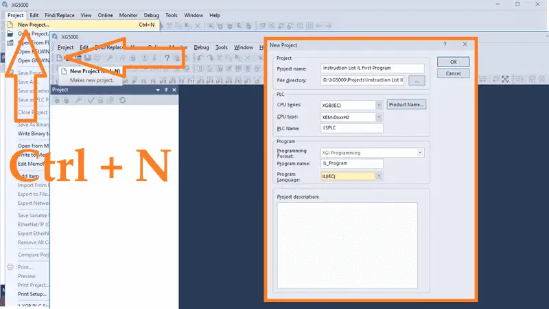
Give the project a name. The directory where this program is to be stored can also be set. Under the PLC section, select the PLC that we will be programming. The CPU series is an XGB (IEC), the type is an XEM-DxxxH2, and we will leave the default name LSPLC. Under the program heading, we can name the IL program and select IL(IEC) as the programming language. A project description can also be put into the new project window to document what we are trying to do. Select OK.
The new program that we named will now be displayed.
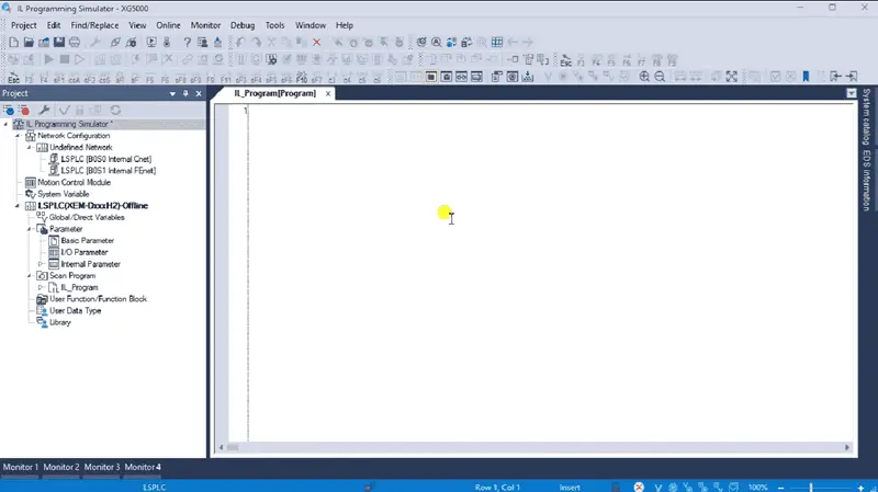
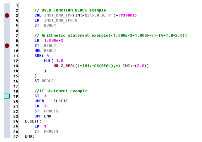
This is where we will program our instruction list (IL) code. If we expand the program name under the project window, you will see the local variable list.
IL programming commands can be seen in the help menu of the XG5000 programming software. We did a summary of these commands in our post “XGB PLC Instruction List (IL) First AI Program.”
Note: As we program, ensure that you select save often. This can be done with the main page icon or main menu | Project | Save…
Using Artificial Intelligence (AI) for IL PLC Instruction List code
Since IL is a text-based language that follows rules and guidelines, it is an ideal candidate for machine learning algorithms. ChatGPT is a powerful AI tool that can generate code in IL for our start-stop circuit. Select the “Reason” option in the AI interface. This will allow us to understand the logic behind our answer.
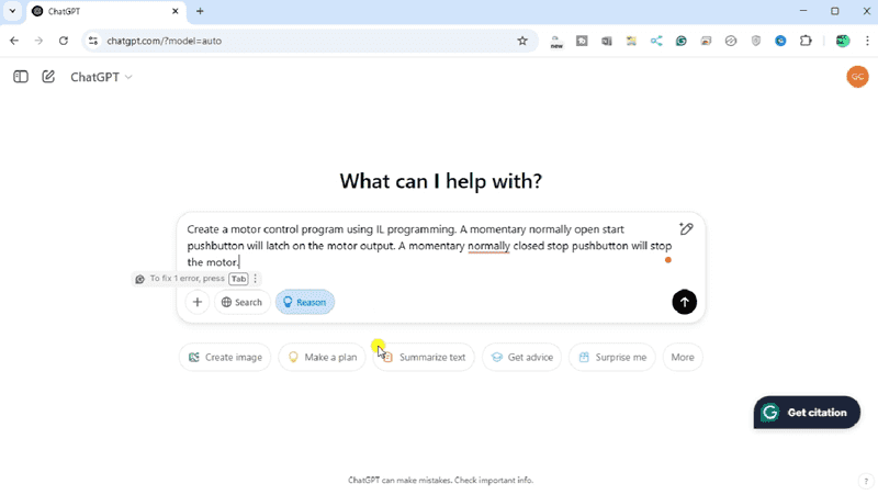
Ask ChatGPT to;
“Create a motor control program using IL programming. A momentary normally open start pushbutton will latch on the motor output. A momentary normally closed stop pushbutton will stop the motor.”
Reasoned for 37 seconds
The user is asking to create a motor control program using IL programming. We want the start pushbutton to latch the motor on and stop it with the stop pushbutton, which is momentary and normally closed.
In IL, the logic is simple: if the stop button is pressed, the motor turns off; if the start button is pressed, the motor activates and stays latched until the stop. I’ll need to focus on how to implement this in the IL language.
I’m thinking of using a latch coil or a rung with latching logic for the motor control. The IL code could look something like this:
Thinking through the motor control structure, we want the start button to latch the motor on until the stop button is pressed. This typical setup involves a combination of normally open and normally closed contacts, which we can implement in IL using instructions like LD, AND, and OR.
I’m now focusing on the correct IL code for motor controller behavior. Here’s what I’ve come up with:
This reflects the desired logic: first, evaluate “I_Start OR M,” then AND it with “I_Stop,” and finally store the result to M. This ensures that M is latched correctly, and the motor will stop if the stop button is pressed, regardless of any prior state. After my tests, this approach avoids the unwanted behavior of leaving the motor running.
ChatGPT did a great job. We can now copy this IL program and paste it into the coding block in the XG5000 programming software.
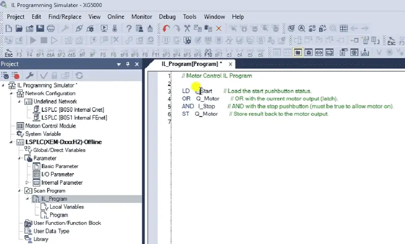
You will see that every instruction in the program is documented. This ensures that we understand what this code is trying to accomplish.
Create the Variable List – XG5000 IL PLC
We have the instruction list code but have not defined the variables we are using. Under the project window in the LSPLC, double-click “Local Variables.”
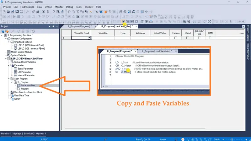
This will call up the Local Variables window for our program. We can now enter the variables that AI has generated for our IL PLC code.
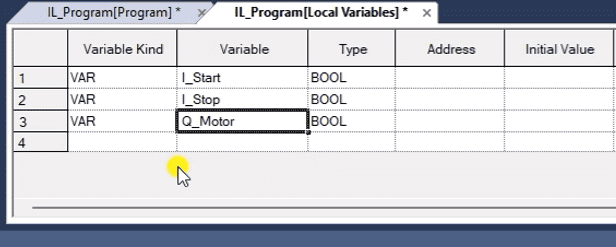
Copy the start, stop, and motor variables into the variable chart. All of these variables are boolean. This means they are either on/off, 1/0, or true/false.
Save the program.
Start the XG5000 Simulator
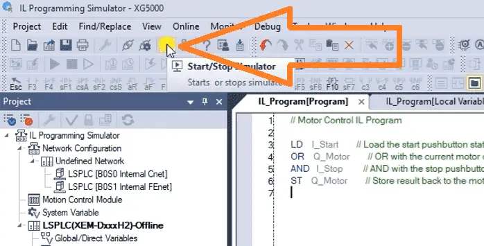
The PLC simulator can be started by selecting the Start/Stop Simulator icon on the main menu. This can also be started by the main menu | Tools | Start Simulator. The XG-SIM window will represent the LS Electric PLC we chose to program.
Our XG5000 PLC software will be shown with communication to the simulator. This is the red bar at the bottom of the XG5000 programming software.
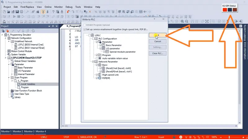
The Write to PLC window will automatically be displayed. XG5000 software treats the simulator like a PLC controller, and you must establish communication and transfer the program. We will leave all of the default settings the same and select OK.
Our instruction list IL start-stop circuit will be loaded into the PLC simulator. The XG5000 writing complete message will be displayed. Select OK.
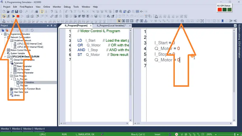
The PLC simulator will be placed automatically in RUN mode. This is indicated by the green bar at the bottom of the XG5000 software. We can close the check program window by selecting the X in the top right corner. Our program is now being executed in the simulator. We can change the font size of the text on the screen by using the zoom in and out on the main menu. You can also start and stop this scan of the program in the simulator by using the icons on the main menu.
Monitoring and Testing the Instruction List (IL) Code – XG5000 PLC
We can use the PLC simulator’s monitoring and troubleshooting tools to observe the behavior of the IL PLC program.
The monitor icon is automatically turned on when we use the PLC simulator.
We can display the inputs and outputs we want to monitor using the monitoring windows. Selecting the IL code or variables is an easy way to add the variables to the monitor list. Once the variables or code are highlighted, select Add from the main menu | Monitor | Add to variable monitor…
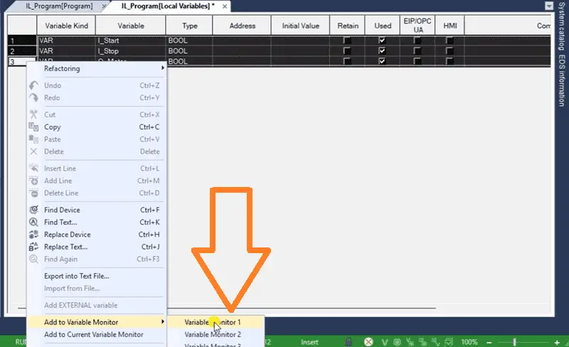
This can also be done by right-clicking on the highlighted variables or code, selecting “Add to variable monitor,” and then choosing the monitor number.
Our selected variables will now be displayed on the monitor number.
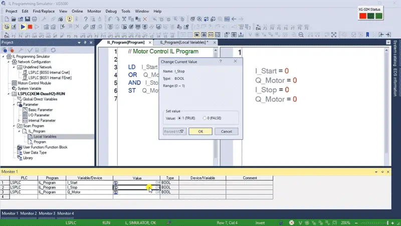
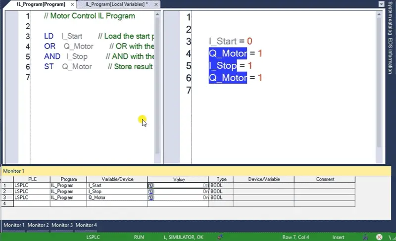
We can change the input variables and observe our program behavior by double-clicking on them.
See the video below to demonstrate using the XG5000 PLC simulator with our instruction list program code.
Adjustments can be made in the program using XG5000 when issues or errors are discovered. We can create and save the necessary changes to our IL program code offline or online and update the code again.
Using the PLC simulator in the XG5000 programming software for instruction list (IL) effectively tests and debugs PLC programs without physical hardware. It provides a safe and efficient environment to validate your logic and ensure proper operation before deploying it to real-world applications. By following the steps outlined above, you can harness the power of the PLC simulator to streamline your development process and deliver reliable PLC programs.
Now that you know more about the XG5000 PLC Simulator for IL programming click here to learn more about entering and modifying your IL code.
To see all of the posts and videos for the XGB PLC, click here.
Download the Start Stop Circuit Sample Program and try it yourself. Let me know how you make out in the comments below.
Watch on YouTube: PLC Programming Made EASY – XG5000 IL Simulator!
LS XGB PLC Additional Information:
LS XGB PLC – Series
– FAQ – Frequently Asked Questions
Product Cut Sheet (XEM-DN32H2 Unit Specifications)
LS PLC Technical Specifications
Manuals:
Interactive Guide
LS PLC User Manual
Other Documents:
PLC Installation Guide
Product Brochure
PLC Statement of Direction
Software and Support:
XG5000 / XG-PM PLC Programming Software
XEM PLC Firmware
Quick Start Procedures
XEM Pulse Servo Wiring Diagrams
Example Applications Directory
If you have any questions or need further information, please contact me.
Thank you,
Garry
If you’re like most of my readers, you’re committed to learning about technology. Numbering systems used in PLCs are not challenging to know and understand. We will walk through the numbering systems used in PLCs. This includes Bits, Decimals, Hexadecimal, ASCII, and Floating Points.
To get this free article, subscribe to my free email newsletter.
Use the information to inform other people how numbering systems work. Sign up now.

The ‘Robust Data Logging for Free’ eBook is also available for free download. The link is included when you subscribe to ACC Automation.