We will now create our first program on Productivity Series Controller. Last time we connected the Productivity 1000 Series PLC with our computer running the Productivity Suite Software. A micro USB and an Ethernet (RJ45) communication link was made to our programmable logic controller. We will now create our first program for our Productivity 1000 Series PLC. Our program will be a simple start-stop circuit for a motor. Here is a post that will explain the logic behind our program circuit.
https://accautomation.ca/how-to-make-a-start-stop-jog-circuit-in-a-plc/
The latest Productivity Suite software version is 3.1.0.11. This is the programming software that we will be using to create our logic for control.
Let’s get started.
Previously in this Productivity 1000 series PLC, we have discussed:
System Hardware – Video
Installing the Software – Video
Establishing Communication – Video
Start a New Project – Productivity First Program
Start the Productivity Suite programming software from the icon on your desktop or from the Windows start menu. ( All Programs | AutomationDirect | Productivity Suite 3.1.0.11 | Productivity Suite )
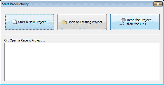
Our Start Productivity window will now appear. Select “Read the Project from the CPU”. Like last time it will present the options for our communication. (USB or Ethernet)
We will select our Ethernet connection to the PLC. This will give us a warning because we currently do not have a program in the PLC. Select OK.
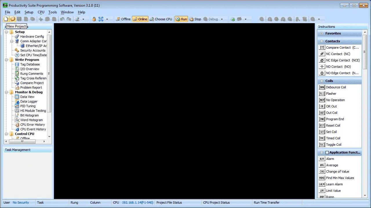
We are now connected to our PLC. Select the New Project icon on the menu options at the top of the screen.
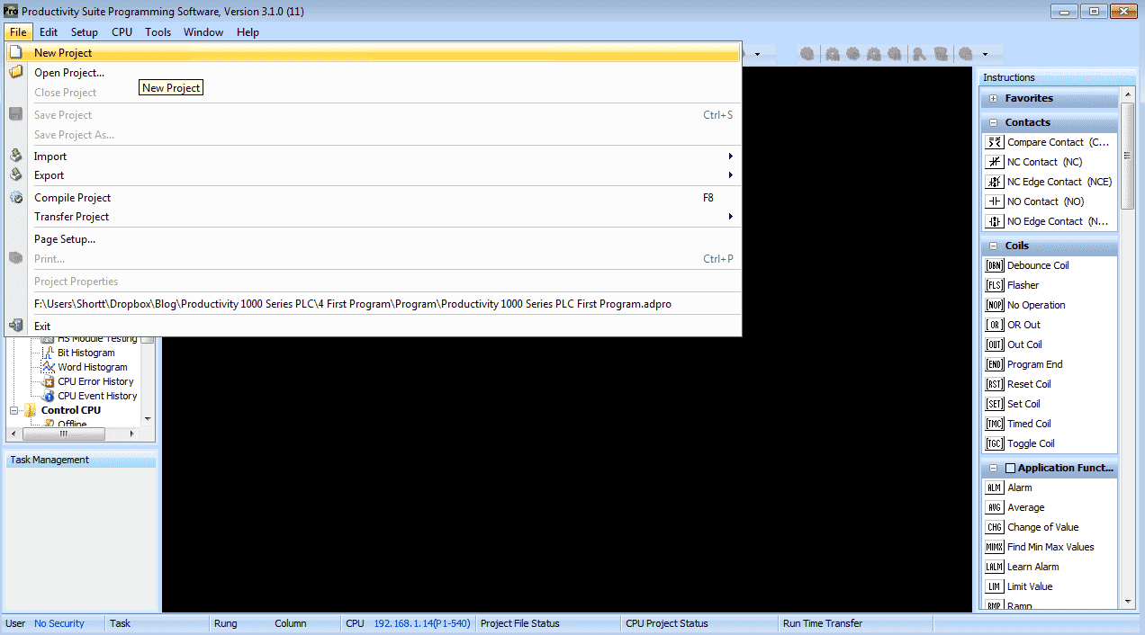
You can also use the main menu and select New Project. (File | New Project)
Choose CPU – Productivity First Program
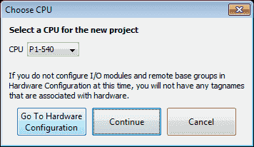
The Choose CPU window will now appear. This will allow us to select the hardware that we will be using for our automation project.
Select P1-540. This is the CPU unit for our Productivity 1000 Series PLC.
Select “Go To Hardware Configuration”
Hardware Configuration – Productivity First Program
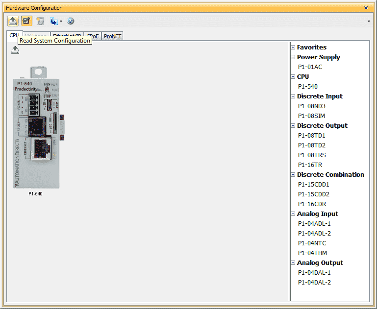
The hardware configuration window will show us our PLC configuration that we will be programming. If we are offline to our hardware, then we can build our system by selecting the units on the left and dragging them to the location in our system next to the CPU. Since we are online, click the “Read System Configuration” icon in the menu. This is the icon in the top left corner.
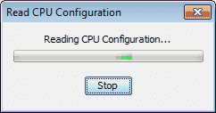
The software will communicate to our PLC for the hardware configuration. It will come back with messages when the physical hardware is different from the software-hardware configured.
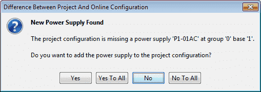
The first message is that we are missing our power supply. Click yes to install this in our project configuration.
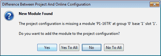
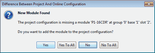
We can select “Yes To All” to have the configuration automatically set for each of the modules that we have on our system. You can also just select “Yes” to have displayed each of the modules to be added.
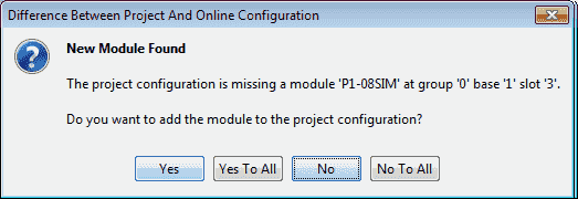
When the last module has been automatically detected and added, we will be presented with a revised hardware configuration window. This should now match our current physical hardware.
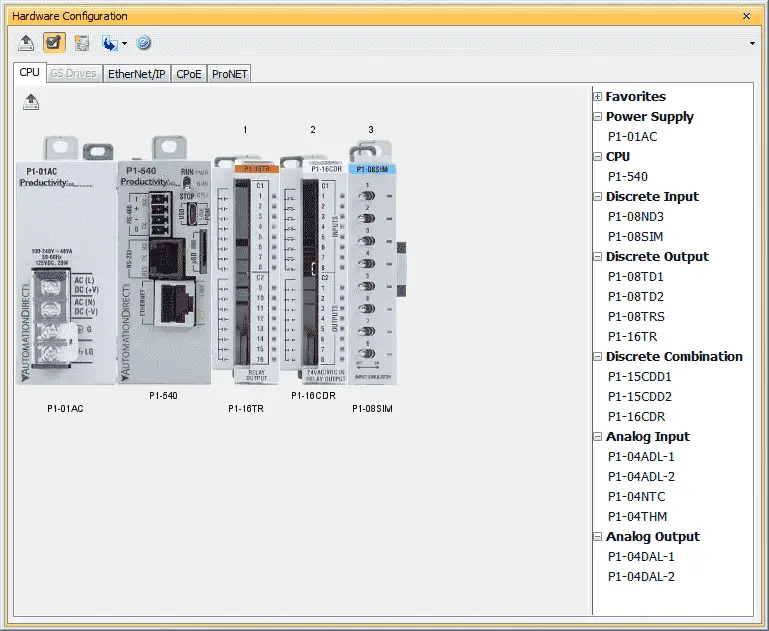
Click the X in the top right corner of the window. This will close our hardware configuration window.
Tag Database – Productivity First Program
We create references to our physical inputs and outputs through our tag database. This is automatically done when we configured our hardware. Default names were generated and given to each of the modules that we added.
Select “Tag Database” under the Write Program heading in the Application Tools. Alternatively you can use the main menu | Edit | Tag Database selection.
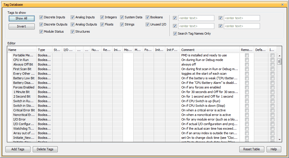
The tag database will show us a list of all of the assigned bits in the CPU. These assigned areas can be automatic or manually generated. To see our physical inputs and outputs that we assigned when configuring the system you can scroll through all of the tags. Another way would be to just select the “Discrete Inputs” and the “Discrete Outputs” to display only.
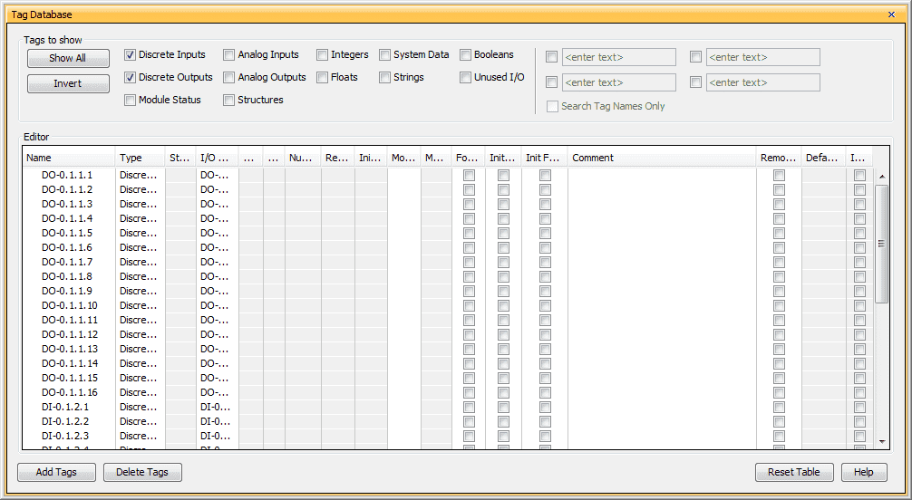
We will now only see our inputs and outputs for our system. The automatic assignment can be read as follows:
DO-0.1.1.1 – Discrete Output – System 0 – Rack 1 – Slot 1 – Bit location 1
So the first switch on our input simulator would be:
DI-0.1.3.1 – Discrete Input – System 0 – Rack 1 – Slot 3 – Bit location 1
Select the X in the top right corner to close the Tag Database window.
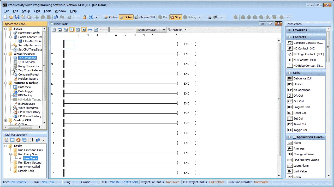
Creating the Ladder Logic – Task
All of the ladder logic is put into groups called tasks. You can have several tasks that will help you split up and organize your program.
On the bottom right area of the Productivity Suite software, you will notice the Task Management window. This is where you can name, organize, and add new tasks to your program.
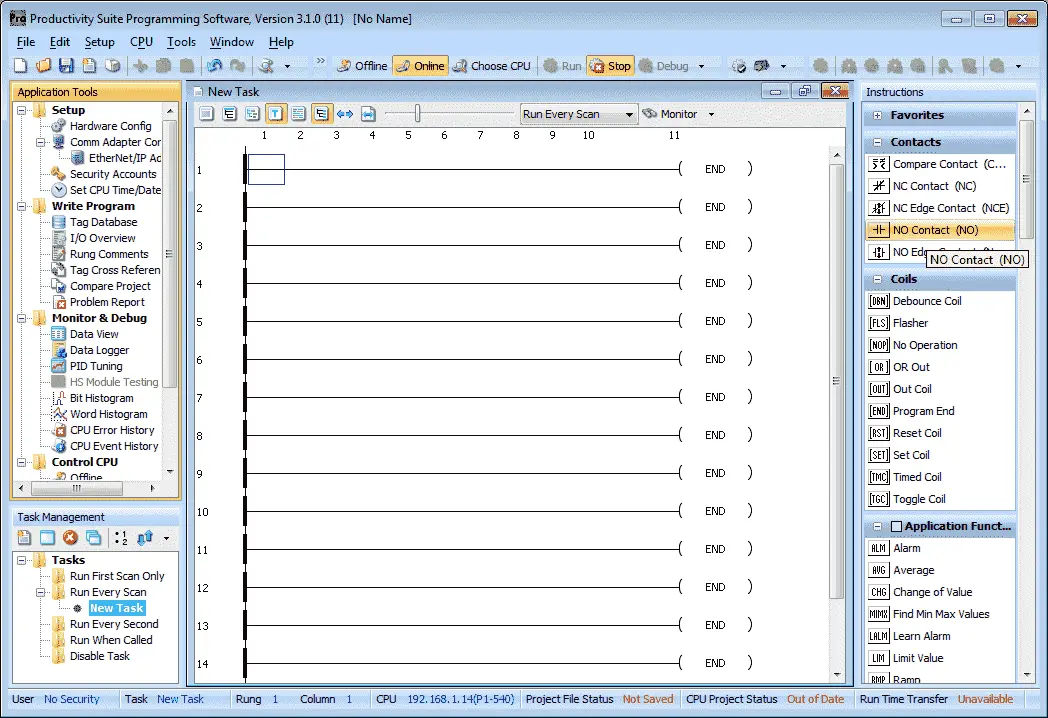
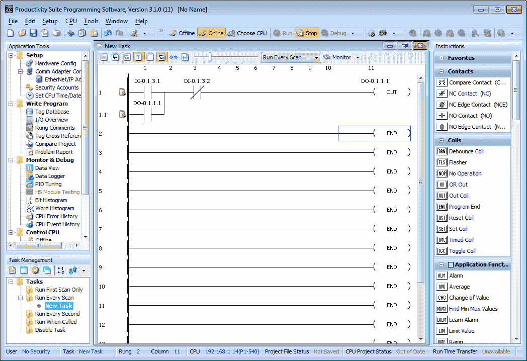
The default new task will be under “Run Every Scan”. This is where we will be creating our first program.
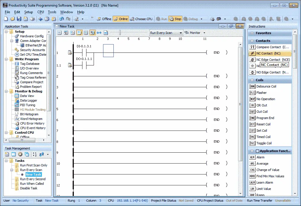
Place your cursor on the top left side of the first rung in the new task window. Double click on the NO Contact under the instructions on the right side.

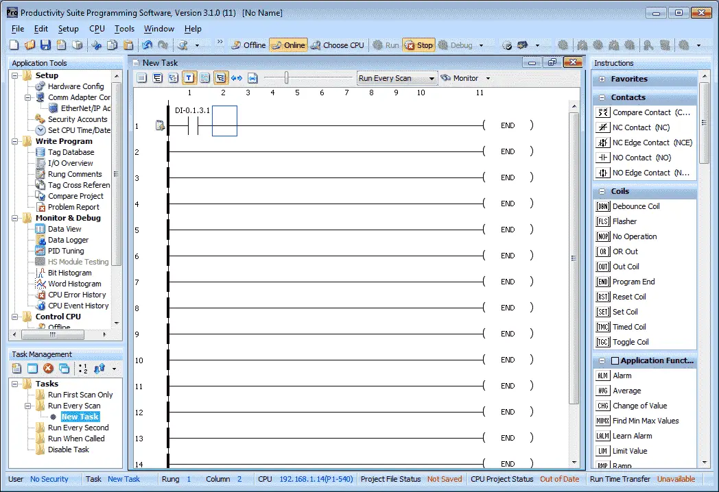
We will select our fist switch on our simulator. DI-0.1.3.1.

The show instruction comment will allow you to write comments documenting information about the location of the instruction in the rung.
Select OK to place this instruction in the rung.
With the cursor now next to the instruction that we just inserted we will now draw a vertical line down. We can use the keyboard combination of Ctrl + Down arrow, or from the main menu select Edit | Wire | Down.

Move the cursor manually under the previous contact.
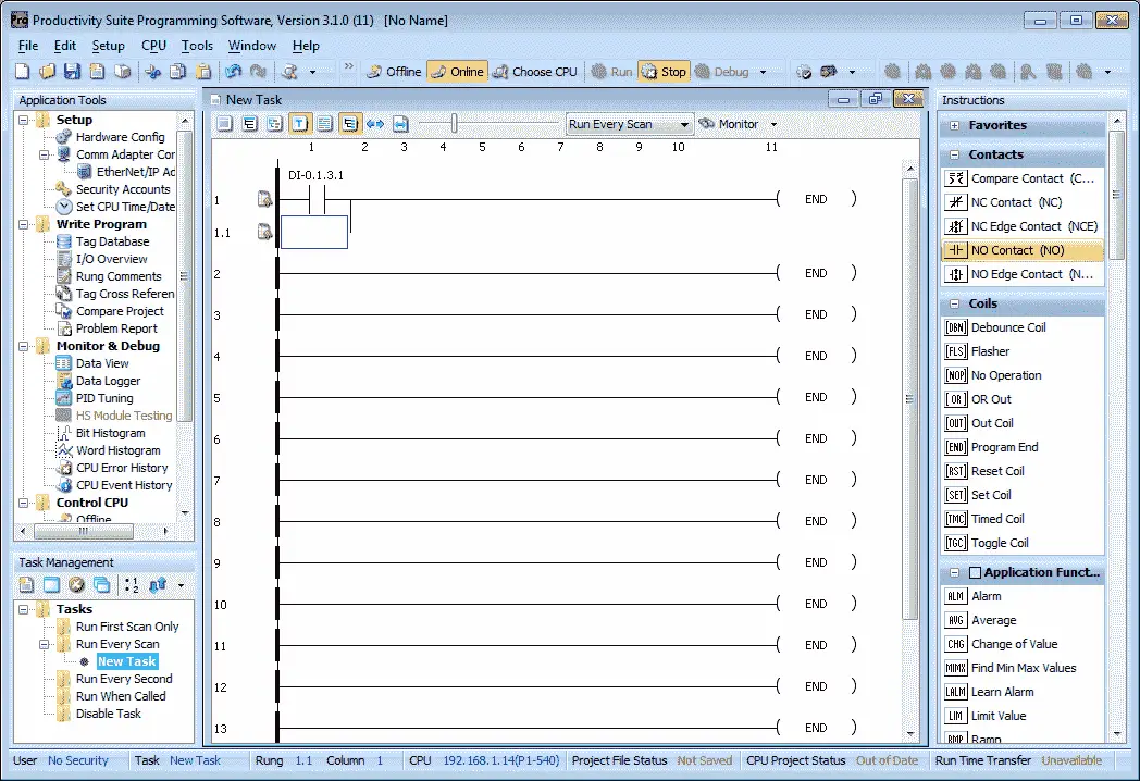
Double click on a NO Contact.
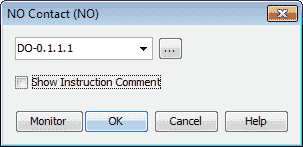
Enter the address of DO-0.1.1.1. This will be the sealing contact for the output.
Put a normally closed contact NC Contact next to the previous ones.
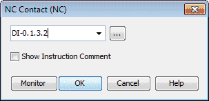
Enter the address of DI-0.1.3.2. This will be our stop contact for our circuit.
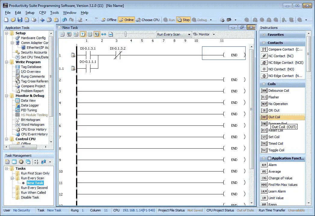
Move the cursor to the end of the rung. Under the coils heading in the instructions, double click on Out Coil.
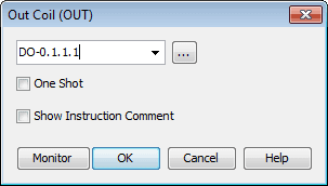
Enter the address D0-0.1.1.1. This is the same output address that we used for our sealing contact. This will actually turn on our first relay output bit of the card. The One Shot check box is available if we want to turn on the output only for one scan. See the following post for an explanation of a one-shot.
https://accautomation.ca/how-to-make-a-one-shot-in-the-plc/
Select OK to finish our rung.
Saving the Program – Productivity First Program
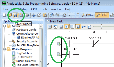
The symbols next to our rung mean that the program has not been saved. Select the Save icon on the top menu or select File | Save Project from the main menu.
You will be asked for a name and location for the saved project.
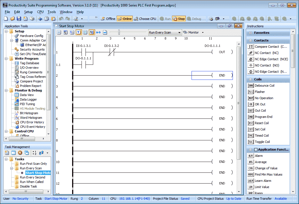
Notice that the information on the bottom of the window now indicates that the project has been saved. The name of the project is also displayed along the top of the window. In our case the name is Productivity 1000 Series PLC First Program.adpro.
We have also renamed our New Task to Start Stop Motor. This is done by right-clicking the Task in the Task Manager and selecting rename. You will then be able to name the task.
Transfer Project to CPU
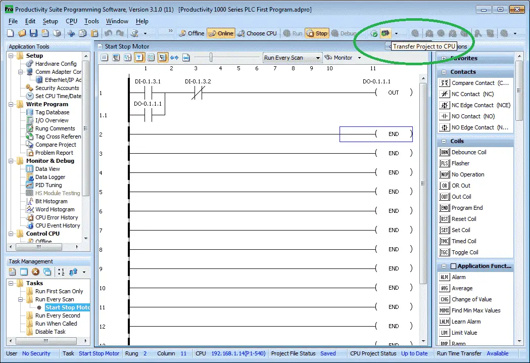
We will now transfer our project to the CPU. Select the transfer project to CPU icon in the top menu. You can also select File | Transfer Project | to CPU from the main menu.
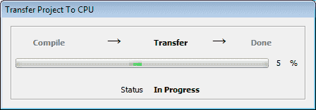
Our program will then compile and transfer to the PLC.
Monitor and Run Program
On the PLC CPU turn the selector switch to run. This will indicate on our Productivity Suite software with the run icon highlighted.
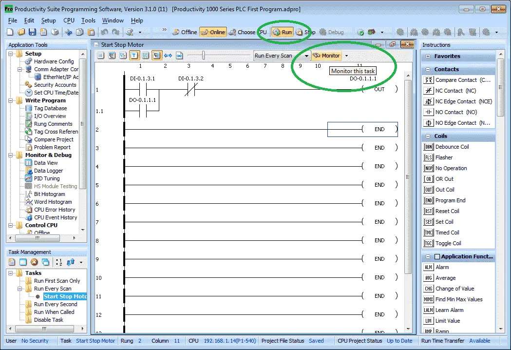
On our task window, you will notice the Monitor icon. Click this icon to enable the monitoring and indication of the IO in our task window.

Red symbols mean off or a logical 0. Green symbols mean on or a logical 1. We can now turn the switches on/off to test our circuit.
Watch the video below to see how easy it is to create a program in our Productivity 1000 Series PLC.
Productivity 1000 Series PLC from Automation Direct
Overview Link (Additional Information on the Unit)
Configuration (Configure and purchase a system – BOM)
User Manual and Inserts (Installation and Setup Guides)
Productivity Suite Programming Software (Free Download Link)
This software contains all of the instruction sets and help files for the Productivity Series.
Next time we will look more at documenting our program in the Productivity 1000 Series PLC.
Watch on YouTube : Productivity 1000 Series PLC First Program
If you have any questions or need further information please contact me.
Thank you,
Garry
If you’re like most of my readers, you’re committed to learning about technology. Numbering systems used in PLC’s are not difficult to learn and understand. We will walk through the numbering systems used in PLCs. This includes Bits, Decimal, Hexadecimal, ASCII and Floating Point.
To get this free article, subscribe to my free email newsletter.
Use the information to inform other people how numbering systems work. Sign up now.

The ‘Robust Data Logging for Free’ eBook is also available as a free download. The link is included when you subscribe to ACC Automation.