XGB Instruction List (IL) in PLC programming is a textual programming language, similar to assembly code, where a program is written as a series of instructions executed sequentially. This is a low-level language used to control Programmable Logic Controllers (PLCs). Instruction List is considered one of the five standard PLC programming languages defined by the IEC 61131-3 standard.
We will program our first Instruction List (IL (IEC)) in our LS Electric XGB PLC. XGB IL programming is commonly used when the programmer is familiar with programming in assembly code. IL can execute quickly, making it suitable for time-critical applications and where compact code is required.
Using Instruction List programming, we will explore the fundamentals of programming an XGB PLC (XGB IL). We will be programming our lighted pushbuttons to control a start-stop circuit. The initial code will be created using regenerative AI. This will show the basics of this IEC programming language. Let’s get started.
Previously in this LS Electric XGB series, we have done the following:
Transform Automation with LS XGB PLC: The Solution
– Unboxing and Powering Video
Install & Com w/ XG5000 PLC – Video
LS Electric XGB PLC Variables and Scope – Video
Wiring Discrete I/O to an XGB PLC – Video
XGB PLC Ladder Logic First Program – Video
XGB PLC Simulator Ladder Logic Diagram – Video
XGB PLC Structured Text First Program – Video
XGB PLC Simulator Structured Text (ST) – Video
XGB PLC Sequential Function Chart (SFC) First Program – Video
XGB PLC SFC Quick Simulator Tutorial – Video
See the list of references for the XGB PLC, including the frequently asked questions (FAQ) at the end of this post.
Start a New Project
Run the XG5000 programming software for the LS Electric PLC controllers. Under the main menu | Project, select ‘New Project.’ This can also be selected using the shortcut key combination of Ctrl + N. There is also a new project icon on the main screen. The New Project window will now be displayed.
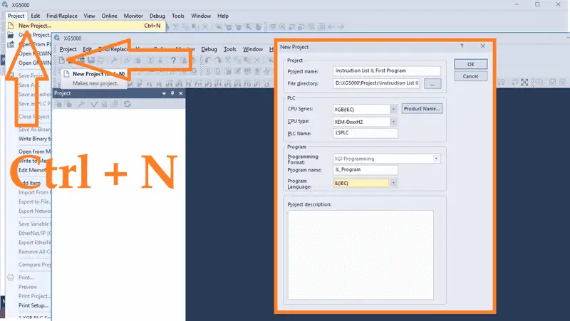
Give the project a name. The directory where this program is to be stored can also be set. Under the PLC section, select the PLC that we will be programming. The CPU series is an XGB (IEC), the type is an XEM-DxxxH2, and we will leave the default name LSPLC. Under the program heading, we can name the IL program and select IL(IEC) as the programming language. A project description can also be put into the new project window to document what we are trying to do. Select OK.
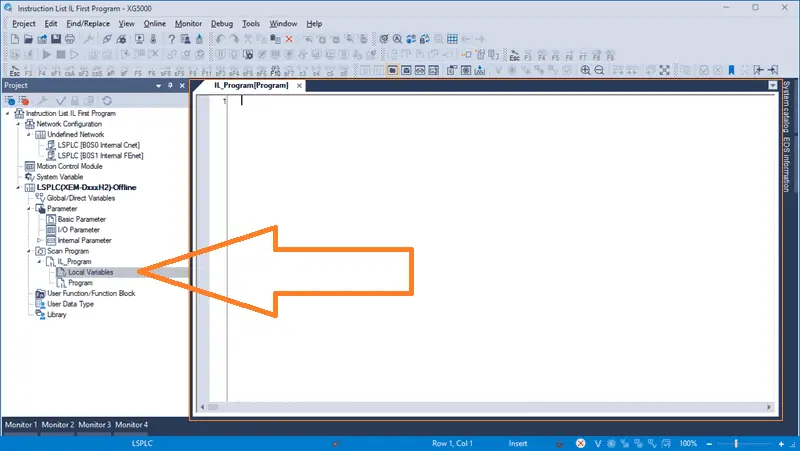
The new program that we named will now be displayed. This is where we will program our instruction list (IL) code. If we expand the program name under the project window, you will see the local variable list.
Note: As we program, ensure that you select save often. This can be done with the main page icon or main menu | Project | Save…
IL Command Summary
Instruction list programs are portable and compatible with all text editors. IL executes one command per line and can be applied to simple PLC programs. Programming is easy for someone familiar with the assembly language, but we will use a simple learning method.
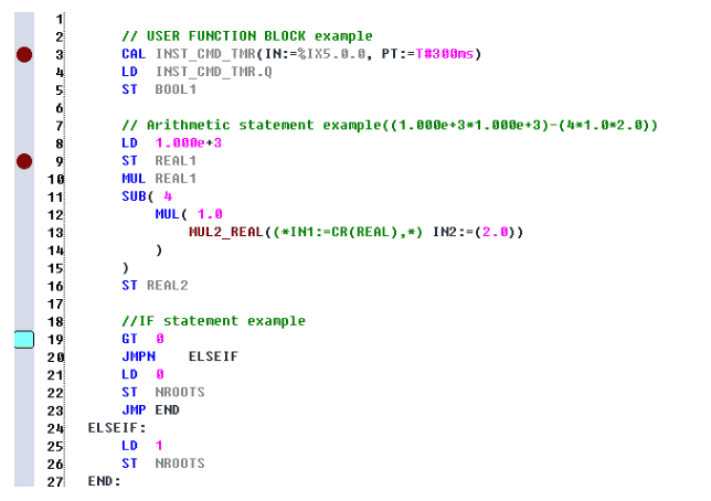
The help menu in Chapter 17 for the IL instructions in the XEM PLC lists all the commands and provides examples.
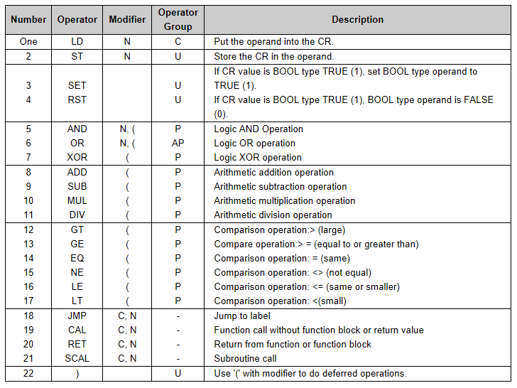
Here is the basic operator table for instruction list programming.
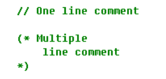
Comments in IL can take two forms. One-line non-executable statements use “//” and are executed until the end of the line. Block non-executable statements process characters between “(*” and “*).”
One of the easiest ways to learn or expand on your knowledge of instruction lists (IL) is to use artificial intelligence (AI).
Artificial Intelligence (AI) for programming IL PLC Instruction List code
Generative artificial intelligence (AI) can be used to create programs using IL. This is because IL is a text-based language that follows rules and guidelines, making it an ideal candidate for machine learning algorithms. ChatGPT is a powerful AI tool that can generate code in IL for a Start Stop circuit.
We can ask ChatGPT to;
“Create an IL plc program with green normally open and red normally closed pushbuttons. When the green push button is pushed and not the red push button, the green LED light will latch on, and the red LED will be off. If the green LED light is on, the red LED is off, and vice versa.”
Response:
Here’s an IL (Instruction List) PLC program that meets your requirements:
Logic Explanation:
- The green pushbutton (PB_Green) is normally open.
- The red pushbutton (PB_Red) is normally closed.
- When the green pushbutton is pressed and the red pushbutton is not pressed, the green LED (LED_Green) will latch ON.
- The red LED (LED_Red) will always be the inverse of the green LED.
IL Program:
Breakdown of Instructions:
LD PB_Green→ Load the state of the green pushbutton.ANDN PB_Red→ Ensure the red pushbutton is NOT pressed (since it is normally closed).OR LED_Green→ Latch the green LED if it was already ON.ST LED_Green→ Store the result to the green LED output.LD LED_Green→ Load the current state of the green LED.NOT→ Invert the state (to ensure red LED is the opposite of green LED).ST LED_Red→ Store the result to the red LED output.
This logic ensures:
✅ Green LED latches ON when the green pushbutton is pressed while the red pushbutton is not pressed.
✅ Red LED is always the inverse of the green LED (one is ON, the other is OFF).
Let me know if you need modifications! 🚀
ChatGPT did a good job. We can now copy this IL program and paste it into the coding block in the XG5000 programming software.
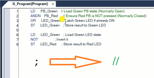
The code uses the semicolon for comments, but IL in the XGB PLC will use the two backslashes \\. We will substitute the backslashes in the program.
Save the program.
Create the Variable List
We have the instruction list code but have not defined the variables we are using. Under the project window in the LSPLC, double-click “Local Variables.”
This will call up the Local Variables window for our program. We can now enter the physical inputs and outputs previously wired to our LS Electric XGB PLC.
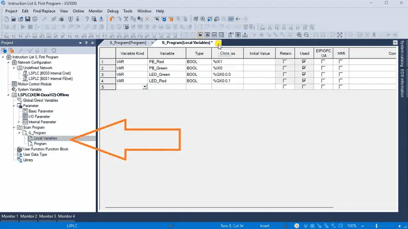
Our sample IL program will control a start-stop circuit. When the start pushbutton is pressed, the green LED will light up, and the red LED will be off. When the stop pushbutton is pressed, the red LED will light up, and the green LED will be off. Initially, the red LED will be on at the start of this IL program. Save the program.
Transfer the Program
Select main menu | Online | Connection Settings…
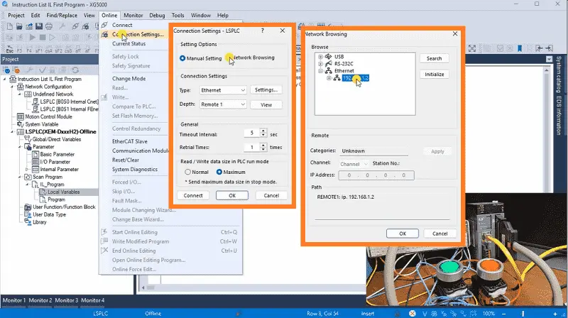
This will call up the Connection Settings window. Select network browsing and then expand the ethernet option. This will search our network for the LS Electric XGB PLC. Click on the IP address found and select OK.
Returning to the connection settings window, we can now select connect.
The bottom of the XG5000 programming window will be red. This tells us that we are communicating with our XGB PLC, which is in stop mode.
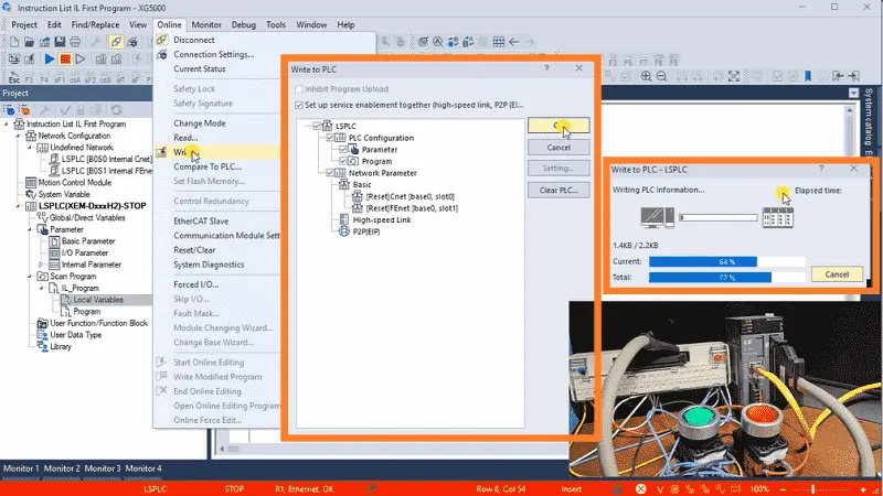
Transfer the XGB IL program to the XGB PLC by selecting Write from the main menu | Online. The Write to PLC window will be displayed. We will leave all the settings as their default and select OK.
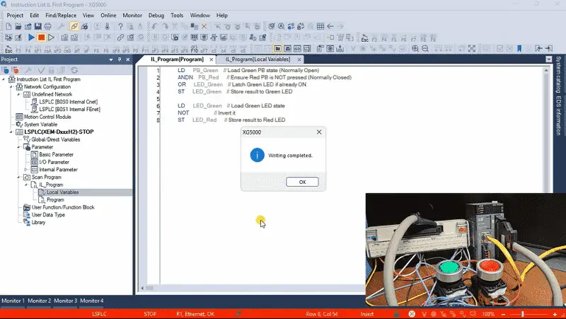
Our program will now be transferred to the PLC. The write complete message can be acknowledged by selecting OK. The PLC connection will then be stopped, which is the blue bar at the bottom of the XG5000 programming software. Select Connect from the main menu | Online. We will once again be connected to the PLC.
Monitor / Modify the Program
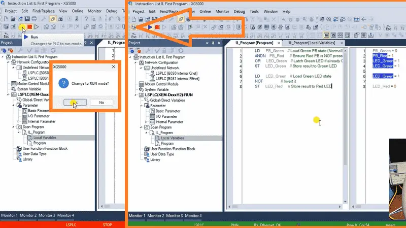
Select the run icon on the main menu. Select Yes to verify that we want to change to RUN mode. The bar at the bottom of the programming software is now green, indicating that we are communicating with the PLC and that the code is running.
Select the monitor icon on the main menu. This will show us the status of our program as it executes in the PLC.
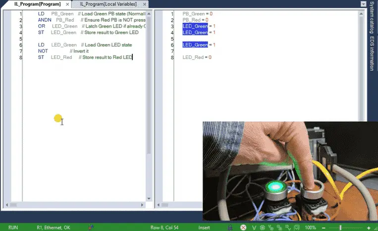
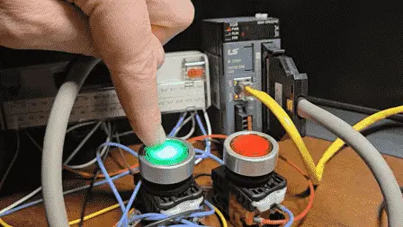
Operate the green and red push buttons to verify the program’s operation. This XGB instruction list IL program was written with the assistance of AI, but the logic does not seem to work. Let’s see if we can determine the cause and correct this start-stop circuit.
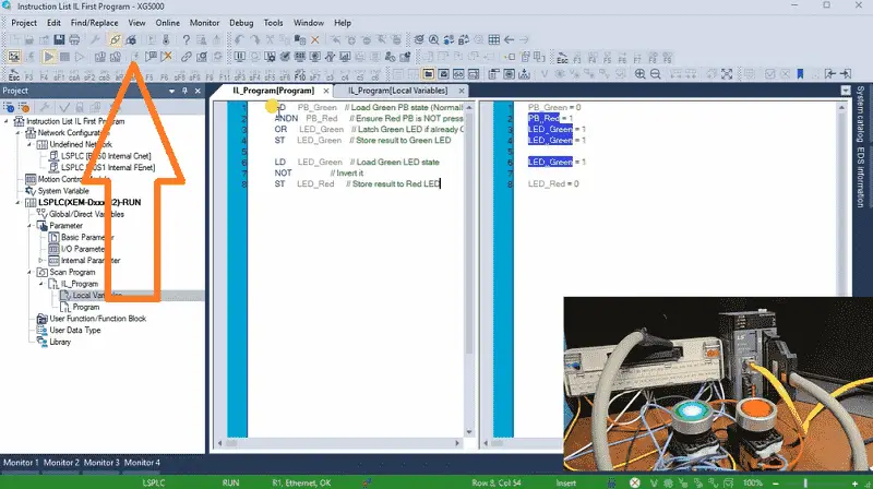
Select the “Start Online Editing (Ctrl + Q)” icon. The blue bars on the programming window for the line numbers indicate that we are programming online.
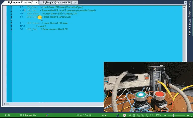
We will change the ANDN (And Not) instruction to an AND instruction. This is because the stop pushbutton is wired normally closed. Once a modification is detected, the entire programming area becomes blue, indicating that a modification from the PLC has occurred.
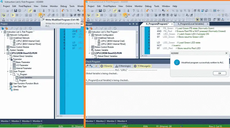
Select the Write Modified Program (Ctrl +W) icon. The changed program will then be transferred to the XGB PLC.
Select the “End Online Editing (Ctrl + U). Select Yes when the confirmation dialog window box displays.
Test the logic again for this start-stop circuit. It is still not working as expected. The LED_Green light will not go off. It helps to follow the logic and think about how it is operating. IL can be quickly translated into ladder logic format.
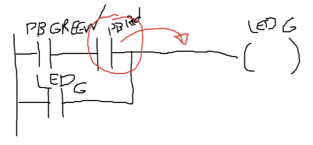
Load pushbutton green and pushbutton red. This is then “OR” with the LED green light. The output is the LED green light. We can see that the stop red pushbutton input is inside the sealing contact from the LED green light. We must move this outside the sealing contact for the start-stop circuit.
Start online editing again. We will change the AND instruction to after the OR instruction in the logic.
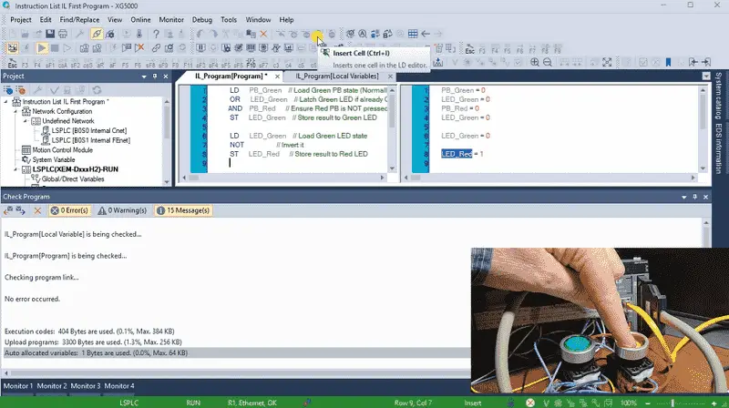
Write the modified program and test the circuit. Test all of the different possibilities for the inputs.
Our logic is now working.
We can monitor the inputs and outputs by selecting them from the local variable list. Right-click the right mouse button and select “Add to Variable Monitor.” We will use Variable Monitor 1.
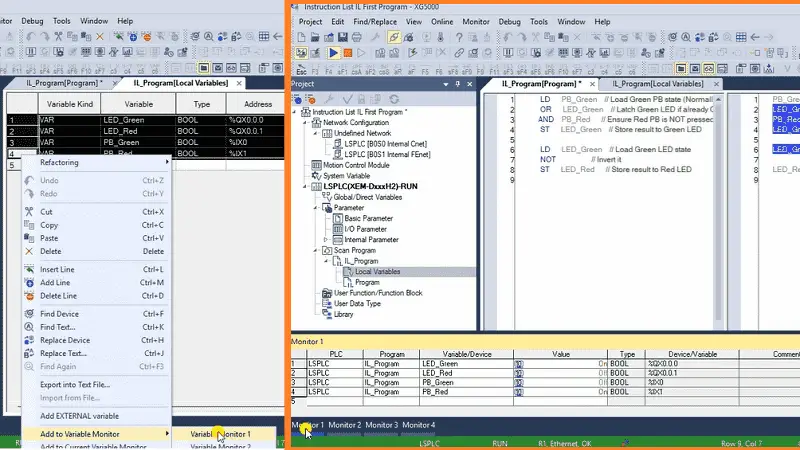
Returning to our XGB IL program, we can end our online programming. Select the Monitor 1 values. We can now operate our push buttons and watch the input and output functions.
Programming an XGB PLC using an Instruction List (IL) language offers a powerful and flexible approach to designing control logic for industrial automation applications. You can develop robust and reliable control programs for XGB PLCs. With continuous learning and adaptation to new technologies, you can leverage IL programming to create innovative industrial automation and control systems solutions. The XG5000 programming software allows you to troubleshoot with visual queues and aids quickly.
Now that you know IL programming, click here to learn more about programming in Structured Text (ST). (Video)
Click here to see all of the available information for the XGB PLC from LS Electric.
Download the Start-Stop Circuit Sample Program and try it yourself. Let me know how you make out in the comments below.
Watch on YouTube: XGB PLC Instruction List (IL) – First Program using AI!
LS XGB PLC Additional Information:
LS XGB PLC – Series
– FAQ – Frequently Asked Questions
Product Cut Sheet (XEM-DN32H2 Unit Specifications)
LS PLC Technical Specifications
Manuals:
Interactive Guide
LS PLC User Manual
Other Documents:
PLC Installation Guide
Product Brochure
PLC Statement of Direction
Software and Support:
XG5000 / XG-PM PLC Programming Software
XEM PLC Firmware
Quick Start Procedures
XEM Pulse Servo Wiring Diagrams
Example Applications Directory
If you have any questions or need further information, please contact me.
Thank you,
Garry
If you’re like most of my readers, you’re committed to learning about technology. Numbering systems used in PLCs are not challenging to know and understand. We will walk through the numbering systems used in PLCs. This includes Bits, Decimals, Hexadecimal, ASCII, and Floating Points.
To get this free article, subscribe to my free email newsletter.
Use the information to inform other people how numbering systems work. Sign up now.

The ‘Robust Data Logging for Free’ eBook is also available for free download. The link is included when you subscribe to ACC Automation.