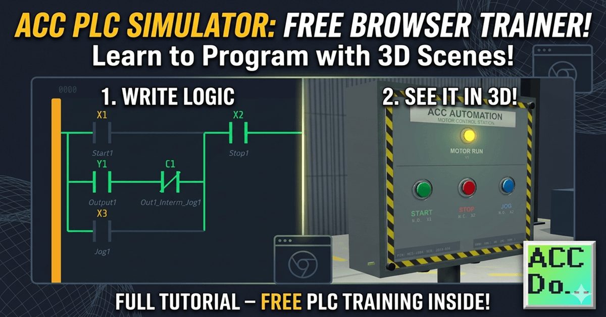
The ACC PLC Simulator is a free, browser-based ladder-logic editor and PLC scan engine. There is nothing to download or install. You open it in Chrome, Edge, or Firefox and start programming immediately.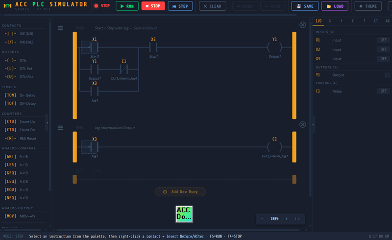
I built this simulator so that anyone learning PLC programming can get hands-on practice without needing hardware. It uses standard PLC register conventions that you’ll find across many different PLC brands. If you can program in this simulator, you can program a real PLC.
⭐ Try it now: accautomation.ca/simulator/
In this post, I’ll walk you through the simulator interface and show you how to use every feature. Let’s get into it.
Opening the ACC Simulator
Open your web browser and go to accautomation.ca/simulator/. The simulator loads immediately. No account, no login, no installation required.
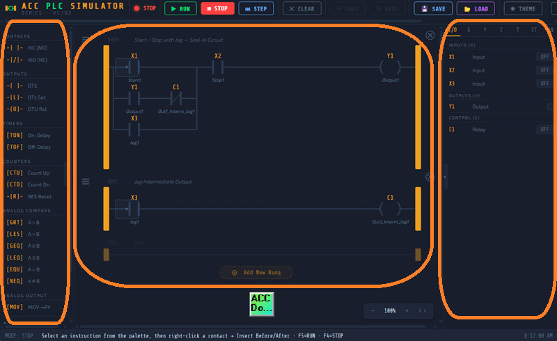
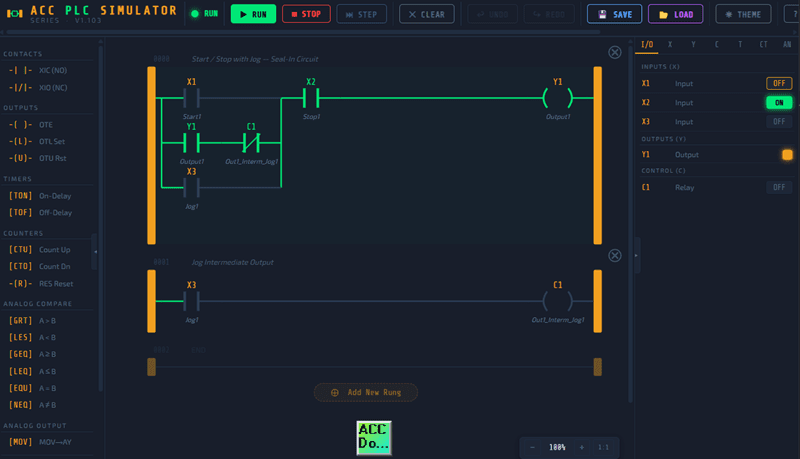
You’ll see three main areas on the screen:
- Left panel – The instruction palette
- Center panel – The ladder logic editor
- Right panel – The I/O monitor
The toolbar across the top gives you access to Run, Stop, Step, Connect, and other controls. The status bar at the bottom shows the current mode, scan time, and messages.
The Toolbar (ACC Simulator)
The toolbar is where you control the simulator’s operating mode.
▶ RUN – Starts the scan engine. The simulator will continuously scan your ladder logic, read inputs, solve the logic, and update outputs. This is equivalent to putting a real PLC into Run mode.
■ STOP – Stops the scan engine. Outputs hold their last state. You can still edit your program in this mode.
⏭ STEP – Executes a single scan cycle while in Stop mode. This is one of the most useful debugging tools. You can toggle an input, press Step, and see exactly what changed. I use this constantly when troubleshooting logic.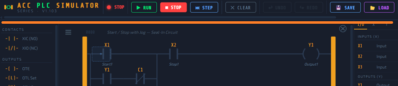
CONNECT – Opens the scene connection panel. This is how you link the simulator to a 3D scene like the Control Panel or Conveyor. More on this below.
The Instruction Palette (ACC Simulator)
The left panel contains all the instructions you can use in your ladder logic program. To add an instruction, you can drag it onto a rung or use the toolbar buttons.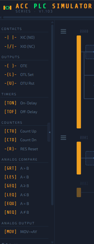
Contacts:
- XIC (Examine If Closed) – Normally Open contact. Passes power when the bit is TRUE.
- XIO (Examine If Open) – Normally Closed contact. Passes power when the bit is FALSE.
Outputs:
- OTE (Output Energize) – Standard output coil. ON when the rung is TRUE, OFF when FALSE.
- OTL (Output Latch) – Latches the output ON. Stays ON even if the rung goes FALSE.
- OTU (Output Unlatch) – Unlatches the output. Turns the bit OFF.
Timers and Counters:
- TON – Timer On Delay
- TOF – Timer Off Delay
- CTU – Count Up
- RES – Reset (resets timers and counters)
Analog Compare:
- GRT – Greater Than (A > B)
- LES – Less Than (A < B)
These are the same instructions you’ll find in most PLC programming environments. The naming conventions follow standard practice.
Register Types (ACC Simulator)
The simulator uses the following register types. If you’ve worked with any PLC before, these will look familiar.
| Register | Type | Description |
|---|---|---|
| X1 – X16 | Digital Input | Physical inputs from buttons, switches, sensors |
| Y1 – Y16 | Digital Output | Physical outputs to motors, lights, valves |
| C1 – C16 | Internal Relay | Intermediate logic flags (no physical connection) |
| T1 – T8 | Timer | On-delay and off-delay timers |
| CT1 – CT8 | Counter | Count up with preset and reset |
| AX1 – AX8 | Analog Input | 0–4095 value (simulates 12-bit analog input) |
| AY1 – AY4 | Analog Output | 0–4095 value (calculated by your logic) |
Inputs (X) can be toggled manually in the I/O panel or driven by a connected 3D scene. Outputs (Y) are controlled by your ladder logic. Internal relays (C) are used for intermediate logic — they don’t connect to anything physical but are essential for organizing complex programs.
The I/O Panel (ACC Simulator)
The right side of the screen is your I/O panel. This is where you interact with your program.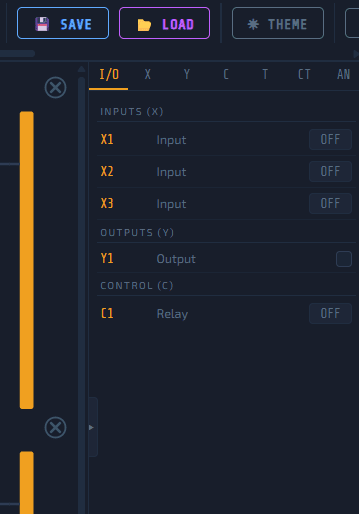
Inputs (X) – Each input has a toggle switch. Click it to turn the input ON or OFF. This is the same as pressing a physical pushbutton on a PLC trainer. When a 3D scene is connected, the scene drives these inputs automatically.
Outputs (Y) – These are read-only indicators. They show the current state of each output as determined by your ladder logic. Green means ON.
Internal Relays (C) – Same as outputs — read-only indicators showing the state of each internal relay.
Analog (AX/AY) – Analog inputs have sliders that let you set a value from 0 to 4095. This simulates a real analog signal like a 4–20mA transmitter. Analog outputs display the value your logic has calculated.
The I/O panel has tabs at the top so you can filter by register type: I/O, X, Y, C, T, CT, or AN.
Building a Program
Here is how I would approach building your first program.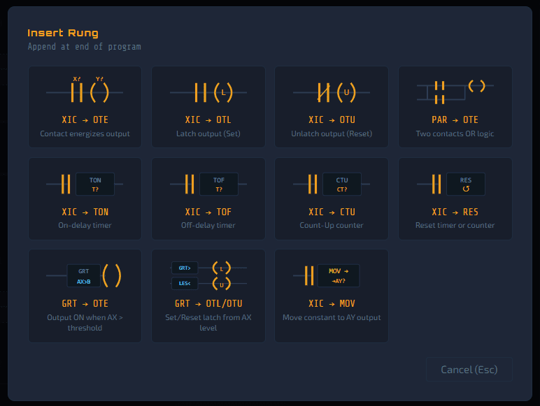
Adding a rung: Click the Add Rung button or right-click in the ladder area. A new empty rung appears with power rails on the left and right.
Adding contacts: Drag a contact from the palette onto the rung, or click the contact button in the toolbar and click where you want to place it. Assign it a register address like X1 or Y1.
Adding outputs: Drag a coil from the palette onto the right side of the rung. Assign it to a Y or C register.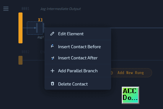
Parallel branches: Right-click on a contact to add a parallel branch. This is how you create OR logic — if any branch has power flow, the output energizes.
Editing addresses: Double-click any element to change its address or add a comment. Comments show up below the element and make your program easier to read.
Deleting elements: Right-click and select Delete, or select the element and press Delete on your keyboard.
Running Your Program
Once your rungs are built:
- Press ▶ RUN or hit F5
- Toggle inputs in the I/O panel
- Watch the ladder logic highlight in green as power flows through TRUE contacts
- Observe the output change in the I/O panel
When a contact is TRUE, it turns green. When a coil is energized, it turns green. The wires between elements also turn green to show the power flow path. This gives you an immediate visual representation of how your logic is executing.
Using Step Mode
Step mode is something I recommend every beginner spend time with. It forces you to think through the logic one scan at a time.
- Make sure the simulator is in STOP mode
- Toggle the inputs you want to test
- Press ⏭ STEP
- Observe what changed — which contacts turned green, which coils energized
- Toggle another input and press Step again
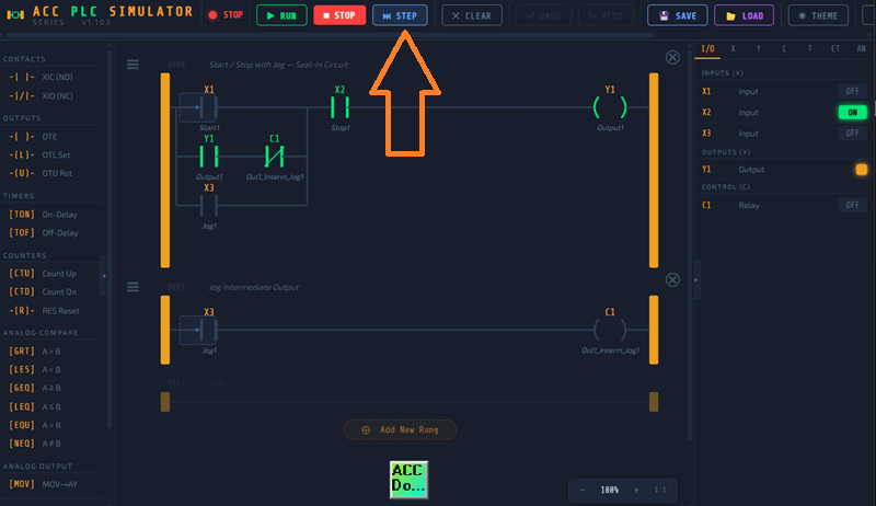
This is how you debug PLC logic. In the real world, you do the same thing — force an input, step through the scan, and verify the output matches what you expect.
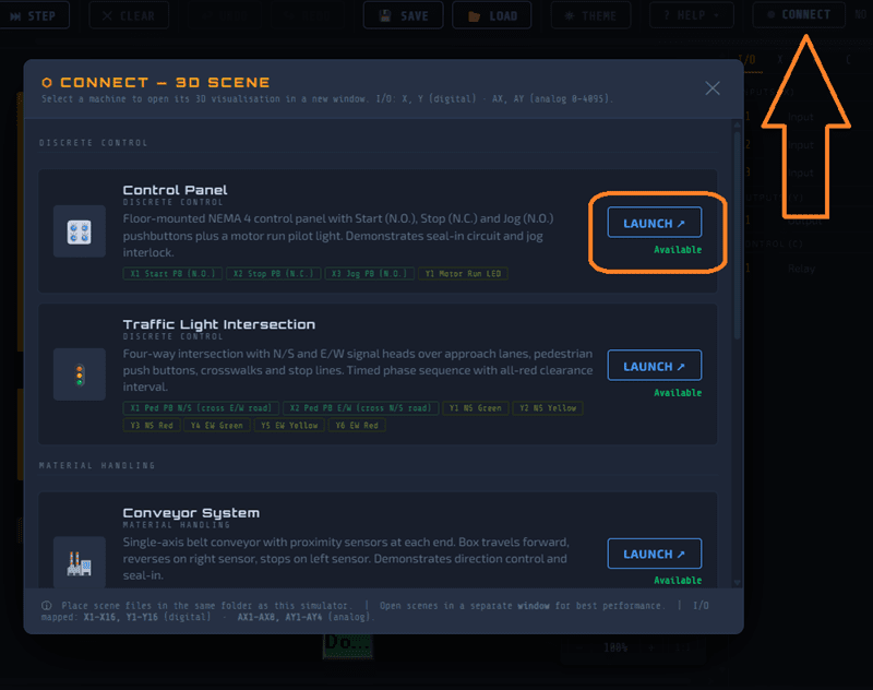
Connecting to a 3D Scene (ACC Simulator)
The simulator has a scene connection system that links your ladder logic to interactive 3D environments. This is what makes the simulator different from anything else out there. Scenes can run independently and be controlled or monitored with your own hardware or PLC simulator using Modbus TCP (Ethernet) or Modbus RTU (Serial).
- Click CONNECT in the toolbar
- Browse the available scenes
- Click LAUNCH on the scene you want to use
- The scene opens in a new browser tab and connects automatically
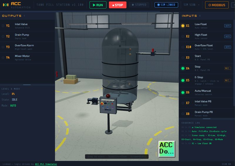
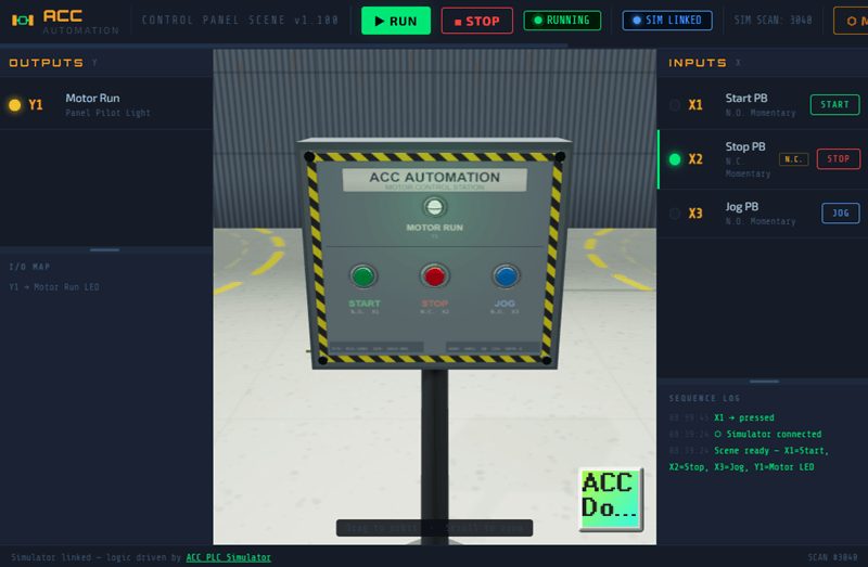
Once connected, the link badge turns blue and shows SIM LINKED. Now the 3D scene drives your X inputs and your Y outputs drive the 3D objects.
Currently available scenes include:
- Control Panel – NEMA 4 enclosure with Start, Stop, and Jog pushbuttons plus a motor run pilot light
- Conveyor System – Belt conveyor with proximity sensors at each end
- Tank Fill Station – Gravity-fed tank with inlet valve, float switches, drain pump, and overflow alarm
- Traffic Light Intersection – Four-way intersection with N/S and E/W signal heads and pedestrian push buttons
- Pick & Place Palletizer – XY gantry arm that picks boxes from a feed conveyor and stacks them on a pallet
Additional scenes currently in development: Sorting Bottle and Panel Wiring.
The connection uses the browser’s BroadcastChannel API. Both tabs must be open in the same browser. No network configuration is required.
The Default Program (ACC Simulator)
The simulator comes preloaded with a two-rung Start/Stop/Jog program. This is a classic motor control circuit that teaches three important concepts:
- Seal-in latch – How an output holds itself on after the momentary Start button is released
- Normally Closed Stop – Why the Stop button is wired N.C. and what that means for the XIC instruction
- Jog interlock – How internal relay C1 blocks the seal-in path so the motor only runs while the Jog button is held
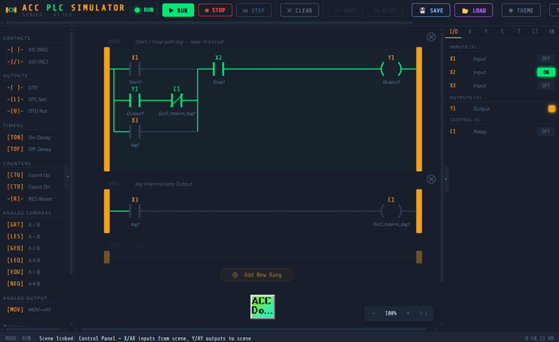
I recommend starting with this default program. Run it, step through it, and make sure you understand every branch before you start writing your own logic.
Keyboard Shortcuts
| Shortcut | Action |
|---|---|
| F5 | Run |
| F4 | Stop |
| F6 | Step (single scan) |
| Ctrl+Z | Undo |
| Ctrl+Y | Redo |
| Ctrl+scroll | Zoom in/out |
| Delete | Delete selected element |
Tips for Getting Started
Here is what I tell everyone who is new to the simulator.
Start simple. Build a single rung with one contact and one coil. Run it. Toggle the input. See the output respond. Then add complexity.
Use the Step button. Don’t just watch things happen in Run mode. Stop the simulator, toggle your inputs manually, and press Step. This is where the real learning happens.
Use internal relays. C registers are your best friend for organizing logic. Instead of putting everything on one rung, break your logic into stages and use C registers as intermediate flags.
Read the comments. The default program has comments on every element. They tell you what each contact and coil is doing. When you write your own programs, add comments too.
Connect a scene. The 3D scenes add a visual layer that makes the logic much easier to understand. When you see a conveyor belt start moving because your Y1 output turned on, it connects the abstract logic to something real.
What’s Next
The ACC PLC Simulator is actively being developed. New scenes, new instructions, and new features are being added regularly. If you have a suggestion for a scene or feature, leave a comment or reach out through the contact page.
Watch the video below for a walkthrough of the simulator in action.
Watch on YouTube:
ACC PLC Simulator – How to Use the Free Browser-Based PLC Trainer
ACC PLC Simulator 🖥️— Learn the Control Panel Scene Tutorial Now!