If you’ve ever wanted to practice PLC ladder logic without buying hardware, the ACC PLC Simulator is built for you. It’s free, it runs in your browser, and it uses standard PLC register conventions. No downloads. No license fees. Just open the page and start programming.
In this tutorial, I’m going to walk you through the Control Panel Scene — a 3D interactive panel with Start, Stop, and Jog pushbuttons connected to the simulator in real time. By the end, you’ll understand how a Start/Stop circuit with a Jog function works, and you’ll have tested it yourself.
Watch on YouTube: ACC PLC Simulator 🖥️— Learn the Control Panel Scene Tutorial Now!
Try it now: accautomation.ca/simulator/
What Is the ACC PLC Simulator?
The ACC PLC Simulator is a browser-based ladder logic editor and scan engine. It supports:
- X registers — Digital inputs (X1–X16)
- Y registers — Digital outputs (Y1–Y16)
- C registers — Internal relays
- T and CT registers — Timers and counters
- AX / AY registers — Analog inputs and outputs (0–4095)
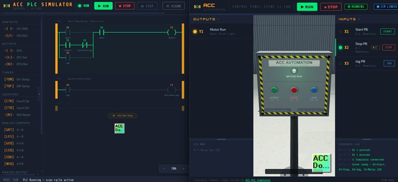
You can add rungs, insert contacts and coils, wire up parallel branches, and put the simulator into Run mode to watch your logic execute in real time. The I/O panel on the right side lets you toggle inputs and monitor outputs just like you would on a PLC trainer.
But the real differentiator is the 3D scene connection system. The simulator can link to interactive Three.js scenes through the browser’s BroadcastChannel API. That means your ladder logic drives 3D objects — conveyors, control panels, indicator lights — in real time.
The Control Panel Scene
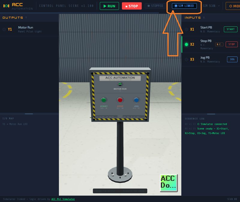
The Control Panel Scene is a floor-mounted NEMA 4 enclosure modeled in 3D. You can orbit around it, zoom in, and click the pushbuttons directly on the 3D model.
Here’s the I/O map:
| Address | Direction | Description |
|---|---|---|
| X1 | Input | Start pushbutton — Normally Open, momentary |
| X2 | Input | Stop pushbutton — Normally Closed, momentary |
| X3 | Input | Jog pushbutton — Normally Open, momentary |
| Y1 | Output | Motor Run pilot light |
The key thing to notice is that X2 is Normally Closed. That means X2 is TRUE at rest and goes FALSE when you press it. This is standard industrial wiring for a Stop button — it’s a safety convention. If the wire breaks, the motor stops.
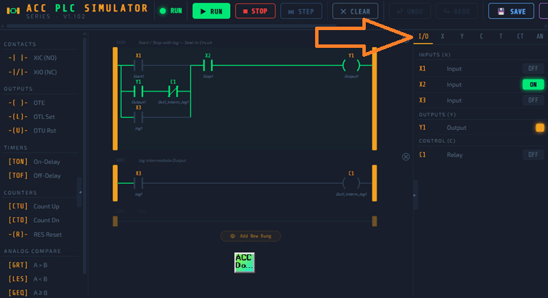
The Default Ladder Logic
When you open the simulator, it comes preloaded with a two-rung program. This is a classic Start/Stop with Jog circuit, and it’s worth studying carefully because it teaches three fundamental PLC concepts in two rungs.
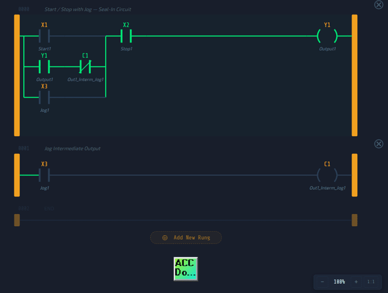
Rung 0 — Start / Stop with Jog — Seal-In Circuit
This rung has three parallel input branches feeding into a series Stop contact and a Y1 output:
Branch 1: XIC X1 (Start — Normally Open contact)
Branch 2: XIC Y1 + XIO C1 (Seal-in path — Y1 must be ON, AND C1 must be OFF)
Branch 3: XIC X3 (Jog — Normally Open contact)
All three branches merge into:
Series: XIC X2 (Stop — this is the NC pushbutton; XIC reads the bit directly, so when X2 is TRUE at rest, the contact passes power)
Output: OTE Y1 (Motor Run)
Rung 1 — Jog Intermediate Output
Input: XIC X3
Output: OTE C1
That’s it. Two rungs. But there’s a lot going on here.
How the Start/Stop Works
Let’s walk through the sequence:
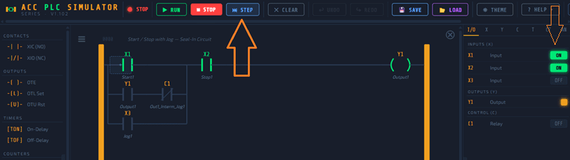
- At rest: X2 is TRUE (NC pushbutton at rest). The X2 contact in Rung 0 passes power. But no input branch is energized, so Y1 is OFF.
- Press Start (X1): X1 goes TRUE. Branch 1 passes power. Power flows through X2 and energizes Y1. The motor runs.
- Release Start: X1 goes FALSE. Branch 1 drops. But Y1 is now TRUE, so Branch 2 activates. The XIC Y1 contact passes power, and the XIO C1 contact also passes power because C1 is OFF. The seal-in holds. Y1 stays ON.
- Press Stop (X2): X2 goes FALSE. The XIC X2 contact in series drops power. Y1 turns OFF. The seal-in breaks because Y1 is no longer TRUE.
That’s your basic seal-in latch. It’s the foundation of almost every motor control circuit in industrial automation.
How the Jog Works
Here’s where it gets clever. The Jog function needs to run the motor only while you hold the button — no latching allowed.
Here’s how C1 makes that happen:
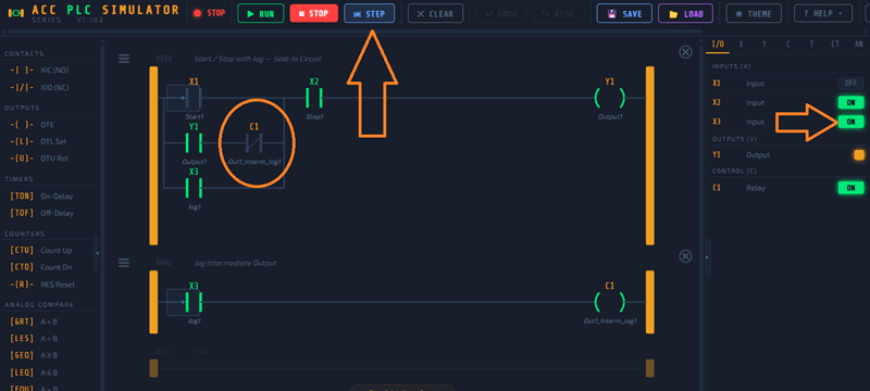
- Press Jog (X3): X3 goes TRUE. Two things happen simultaneously:
- In Rung 0, Branch 3 (XIC X3) passes power. Y1 energizes. Motor runs.
- In Rung 1, XIC X3 passes power to OTE C1. C1 goes TRUE.
- The interlock: Back in Rung 0, Branch 2 has XIO C1 — a Normally Closed contact on C1. Since C1 is now TRUE, this contact OPENS. The seal-in path is blocked.
- Release Jog (X3): X3 goes FALSE. Branch 3 drops. C1 drops (Rung 1). Y1 turns OFF. No seal-in occurred because C1 was blocking Branch 2 the entire time X3 was pressed.
The result: the motor runs only while you hold the Jog button. The moment you release it, everything drops. That’s exactly how a real Jog function works on a factory floor — it’s a deliberate safety feature.
Connecting the Scene
To connect the Control Panel Scene to the simulator:
- Open the simulator at accautomation.ca/simulator/
- Click the CONNECT button in the toolbar
- Find the Control Panel card in the scene list
- Click LAUNCH
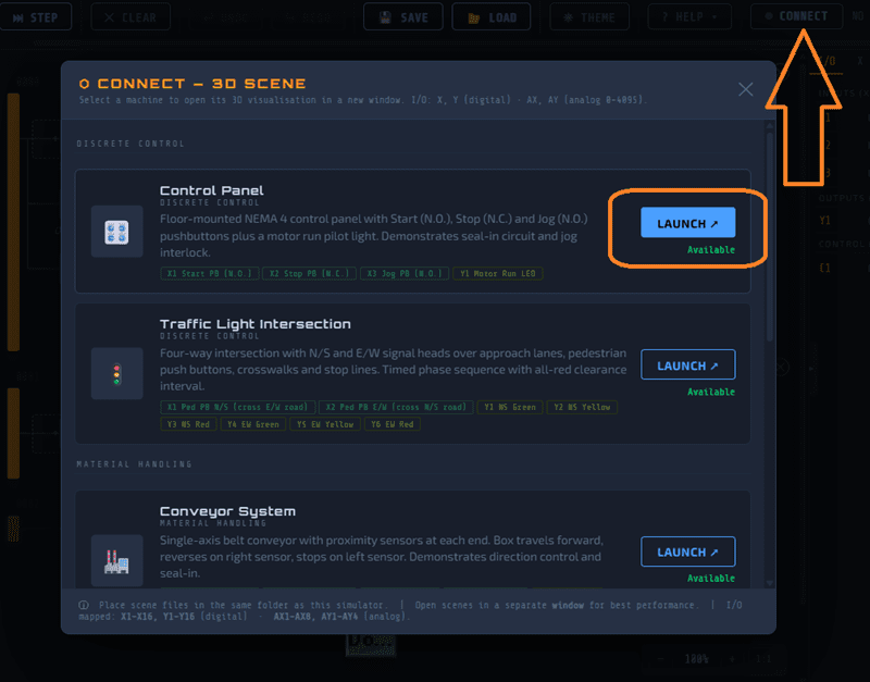
The scene opens in a new window and connects automatically through the BroadcastChannel API. You’ll see the link badge turn blue and display SIM LINKED in both the simulator and the scene.
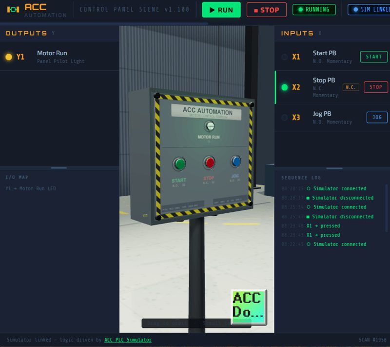
Once linked:
- X inputs (X1, X2, X3) are driven by the 3D panel pushbuttons
- Y outputs (Y1) drive the pilot light on the 3D panel
- The simulator’s scan engine solves the ladder logic every cycle and broadcasts the results back
You can also click the pushbuttons in the scene’s side panel if you prefer that to clicking on the 3D model.
Try It Yourself
Here’s a quick test sequence once you’re connected:
- Put the simulator in Run mode (F5 or click the Run button)
- Press the green Start button on the 3D panel
- Watch Y1 turn ON — the pilot light glows green
- Release Start — Y1 stays ON (seal-in)
- Press the red Stop button — Y1 turns OFF
- Now press and hold the blue Jog button — Y1 turns ON while held
- Release Jog — Y1 immediately turns OFF
That’s the entire circuit. Start latches. Stop breaks the latch. Jog runs without latching. Everything you’d see on a PLC wired to a real panel.
What You Learned
In this tutorial, you covered:
- Seal-in latch — How Y1 holds itself on through Branch 2 after the Start button is released
- Normally Closed wiring — Why X2 is TRUE at rest and how XIC reads it
- Jog interlock — How C1 blocks the seal-in path during Jog to prevent latching
- Scene connection — How BroadcastChannel links the simulator to a 3D scene in real time
These aren’t academic concepts. This is exactly how motor control works in every manufacturing plant running PLCs. Everything you practiced here transfers directly to a real PLC programmed in its native programming software.
What’s Next
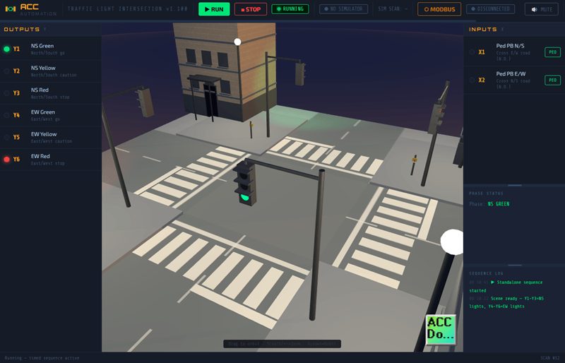
The simulator has more scenes coming — a Conveyor System, a Tank Fill Station, a Traffic Light Intersection, and a Pick & Place Palletizer are already available. More are in development. Each scene introduces different I/O patterns and control challenges.
If you want to take it further, try modifying the default program. Add a timer so the motor auto-stops after 10 seconds. Add a counter to track how many times Start was pressed. Use analog compare instructions to enable the motor only when AX1 exceeds a threshold. The simulator supports all of these.
Head over to accautomation.ca/simulator/ and try it yourself. If you found this helpful, subscribe to ACC Automation on YouTube for more PLC tutorials. And leave a comment telling me what scene or circuit you’d like to see next.
Watch on YouTube: ACC PLC Simulator 🖥️— Learn the Control Panel Scene Tutorial Now!
— Garry