We will now be looking at LEDs that we can wire and program using our Arduino Uno super starter kit. Light-emitting diodes (LEDs) are semiconductor devices that will show light when current passes through them. This light is produced within the solid semiconductor material so it can be called a solid-state lighting device.

We will be looking at the wiring of LEDs with our breadboard. Different resistor values will be used to change the LED light brightness. We will discuss how we can calculate the amount of current passing through our LED.
An RGB LED and Red LED will then be wired to our Arduino UNO. The brightness and color of our LEDs will then be changed through the programming of the Arduino Uno. PWM outputs will be used in our program (sketch). Let’s get started.
A full list of posts in this series can be obtained at the following location:
Arduino Uno Software Super Starter Kit
Previous posts in this Arduino Uno Super Starter Kit Series:
Hardware and Powering – Video
Software – Video
Watch the video below of the operation of LEDs on our starter kit. Elegoo Super Starter Kit UNO R3.
Arduino Uno Super Start Kit Breadboard
A breadboard allows you to create prototype circuits without soldering connections. This provides quick and easy testing of your circuits.
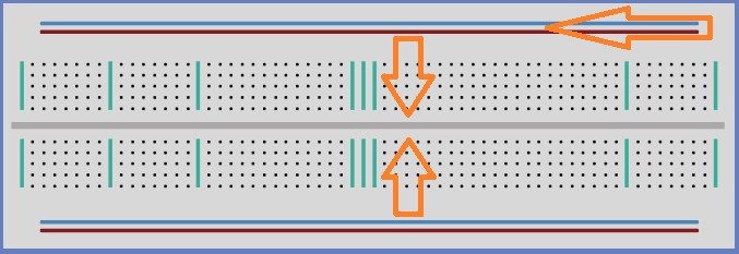
The breadboard holes are for placing wires or components for connections. Power connections usually run across the top and bottom of the unit. This is for +VDC and GND. The middle holes run vertically connected. There is a break in the middle indicating that no connection is made. This allows components to straddle the middle and be connected on both sides.
These breadboards are great for prototyping the circuit but not in production because the push-fit is temporary. Usually, components would be soldered together for a permanent connection.
LEDs
LEDs make great indicator lights for the operator. Power supplies will almost always have an LED to indicate power is present.
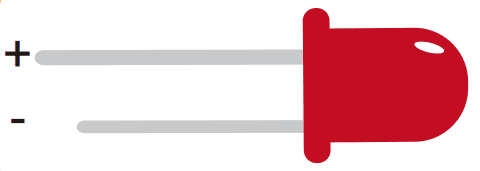
There are two ways to tell the difference between the positive and negative leads of the LED. The positive lead is longer. There is a flat edge to the case of the LED where the negative lead enters the body.
We will be connecting 5mm red LEDs to three different resistors. These LED’s can handle up to about 20mA of current.
Resistors
Resistors are used to restrict the flow of current in a circuit.

We will be using resistors to limit the amount of flow going to the LED. This will make the LED brighter or dimmer depending on the amount of current.
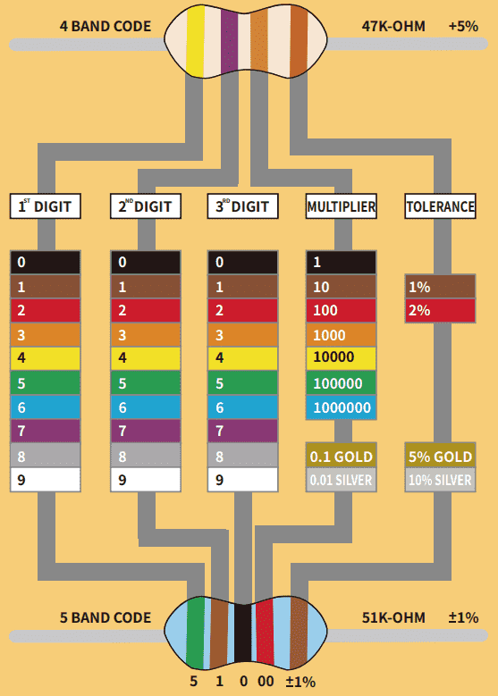
Resistors have a color code to determine their value. We have four or five stripes of color to determine the size of the resistor.
Example:
We will be using the following three resistors in a circuit.
220 ohm = Red, Red, Brown, Brown
1K ohm = Brown, Black, Red, Brown
10K ohm = Brown, Black, Orange, Brown
Ohm’s Law
Electrical circuits have the following three components: Volts, Current, and Ohms.
Ohm’s law is used to analyze an electrical circuit. It explains the relationship between the three components.
V=IR or I = V/R or R=V/I
Voltage (V or E) is the pressure from an electrical circuit’s power source that allows charged electrons (current) through a conducting loop.
Current ( I ) is the rate at which electrons flow past a point in an electrical circuit. It is measured in amps (A)
Ohms ( R )is the resistance to the current between two points.
Given any two of the components, you can find the third.
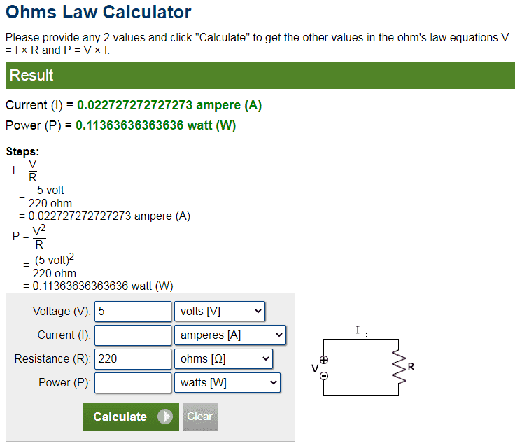
Here is an online ohm’s law calculator. I find this good because it shows how the calculation was done. In this example, we are finding how much current will be put through our LED if I connect it with 5VDC and a 220-ohm resistor. The answer is about 22 milliamps
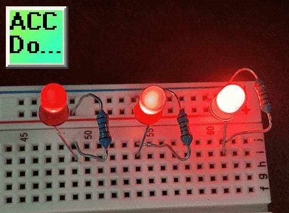
Wiring Three LEDs to Different Resistors
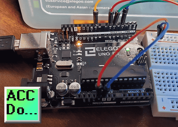
Using our breadboard, we will now wire three of our red LEDs to three different resistors. We will use the 5VDC supply and GND (0VDC) on our Arduino Uno to power the circuit.
Note: All pins labeled GND are connected on the Arduino Uno.
The negative pin of the LED is connected to the GND. The other side of the led is connected to a resistor. The other end of the resistor is connected to the 5VDC to complete the circuit.
Using ohm’s law I = V/R you can calculate the amount of current following in each of the circuits. A higher current in the circuit means brighter light on the LED.
Note: Connecting the LED without a resistor in the circuit will cause too much current to flow destroying the LED. Ohm’s law will show you prove to you the amount of current it will draw.
Watch the video below to see the LED lights wired and working using different resistors.
RGB LED
RGB (Red, Green, and Blue) LEDs look like regular LEDs but they have three different LEDs inside.
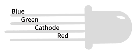
These LEDs come in two different versions, common anode or common cathode. Common anode uses +5VDC on the common pin. GND or 0VDC connects to the common pin for the common cathode.
We will be using the common cathode for our example.
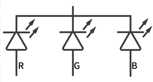
Here is the symbol for the RGB LED. The arrows coming from each of the diodes indicate light. As mentioned above this is just like having three individual LEDs.

This is just like mixing paint to make different colors. We can change the amount of current flowing in each of the LEDs to create different colors.
Arduino Uno PWM Outputs to Control LEDs
Changing resistors all of the time for the different colors can be very time-consuming.
The Arduino Uno has outputs that we can adjust to achieve the same effect as changing resistors. These outputs are PWM (Pulse Width Modulated) and are indicated on the Arduino Uno with a ~ symbol.
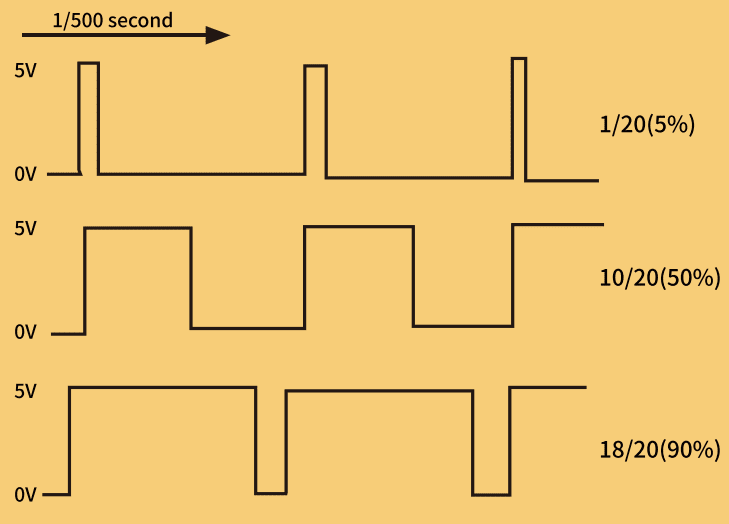
PWM outputs basically turn on/off an output quickly based on a duty cycle. This duty cycle will determine the amount of time that it is on which will limit the current going to the attached device. Using an Analog Write we can specify a value between 0 and 255.
Wiring PWM Outputs – Arduino Uno
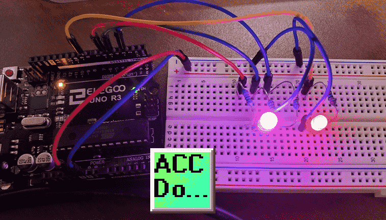
We will be wiring the RGB LED and a red LED. Each of the LEDs will have a 220-ohm resistor to ensure that the current is limited to the device.
The negative of the red LED is connected to GND. The positive side is connected to one side of the resistor. The other side of the resistor will go to input 9.
The RGB common is connected to the GND. Each of the RGB ends is connected to a 220-ohm resistor. The other end of the resistor will be connected to inputs 3, 5, and 6.
Arduino Uno PWM Program Sketch
Our program will start the RGB LED in the Red color state, then fade to green, then fade to Blue, and finally back to the Red. This will demonstrate the colors that are possible with the RGB LED. Our red LED will follow the RED in the RGB LED. This will show you the amount of red in the color being displayed.
//https://accautomation.ca/
//Program modified from Elegoo Super Starter Kit Arduino Uno R3

//The RGB LED is controlled by pins 3, 5 and 6
// define pins
#define BLUE 3
#define GREEN 5
#define RED 6
//Red Led will mimic the intensity of the Red in the RGB LED - pin 9
#define REDLED 9
void setup()
{
// Specify an output control on the pins
pinMode(RED, OUTPUT);
pinMode(GREEN, OUTPUT);
pinMode(BLUE, OUTPUT);
pinMode(REDLED, OUTPUT);
// Set the outputs on (high) or off (low)
digitalWrite(RED, HIGH);
digitalWrite(GREEN, LOW);
digitalWrite(BLUE, LOW);
digitalWrite(REDLED, HIGH);
}

// define variables. This will store our output PWM value between 0 and 255
int redValue;
int greenValue;
int blueValue;
int redLEDValue;
// main loop - This loop is constantly cycling. The above is needed for the setup of the variables.
void loop()
{
#define delayTime 10 // fading time between colors (10 milliseconds)
  redValue = 255; // choose a value between 1 and 255 to change the color.
  greenValue = 0;
  blueValue = 0;
  redLEDValue = redValue; // set the red LED as the same as the RED in the RGB LED


  //The increments happen every 0.010 seconds 255 times for the full range of the color(s)
  //Loop to decrement RED and increment GREEN. BLUE is 0
  for (int i = 0; i < 255; i += 1) // fades out red bring green full when i=255
  {
    redValue -= 1;
    greenValue += 1;
    analogWrite(RED, redValue);
    analogWrite(GREEN, greenValue);
    analogWrite(REDLED, redValue);
    delay(delayTime);
  }
  redValue = 0;
  greenValue = 255;
  blueValue = 0;


//Loop to decrement GREEN and increment BLUE. RED is 0
for (int i = 0; i < 255; i += 1) // fades out green bring blue full when i=255
{
greenValue -= 1;
blueValue += 1;
analogWrite(GREEN, greenValue);
analogWrite(BLUE, blueValue);
delay(delayTime);
}
redValue = 0;
greenValue = 0;
blueValue = 255;

//Loop to decrement BLUE and increment RED. GREEN is 0
for (int i = 0; i < 255; i += 1) // fades out blue bring red full when i=255
{
// The following code has been rearranged to match the other two similar sections
blueValue -= 1;
redValue += 1;
analogWrite(BLUE, blueValue);
analogWrite(RED, redValue);
analogWrite(REDLED, redValue);
delay(delayTime);
}
}
Use the Verify and upload icons on the Arduino IDE software to transfer the program sketch to the Arduino Uno R3 unit.
Download the Arduino Uno LED program sketch here.
Watch the video below for the operation of the LED and RGB LED on our Arduino Uno Super Starter Kit.
Elegoo Links:
Service
service@elegoo.com (USA and Canada)
EUservice@elegoo.com (Europe)
Arduino Compatible Links:
Product Hardware
Elegoo UNO Project Super Starter Kit
Elegoo Download Page
Amazon.com
Amazon.ca
Software
– Arduino IDE (Integrated Development Environment)
– Productivity Blocks (Development Timesaver)
– Productivity Blocks Documentation (Wiki)
Community
– Arduino Blog
– Arduino Forum
– Arduino UNO Facebook
Next time we will look at digital inputs for our Arduino Elegoo super starter kit UNO R3.
Watch on YouTube: Arduino Uno Super Starter Kit LEDs
If you have any questions or need further information please contact me.
Thank you,
Garry
If you’re like most of my readers, you’re committed to learning about technology. Numbering systems used in PLC’s are not difficult to learn and understand. We will walk through the numbering systems used in PLCs. This includes Bits, Decimal, Hexadecimal, ASCII, and Floating Point. To get this free article, subscribe to my free email newsletter.
Use the information to inform other people how numbering systems work. Sign up now. The ‘Robust Data Logging for Free’ eBook is also available as a free download. The link is included when you subscribe to ACC Automation.