Assign a static IP to CLICK PLUS PLC easily! You know the drill. Another project, another piece of hardware. This time, it was a Click PLUS PLC. We had previously assembled the hardware using the Automation Direct website to ensure that all of the components were accounted for. Before it could orchestrate a single solenoid or read an encoder pulse, it needed an identity on the network. Without a proper Click IP address, it was just a rather expensive paperweight.
So, I prepped my battle station: the laptop was open, the familiar Click PLC software was already loaded, and a hot mug of coffee was at hand. Let’s get this done.
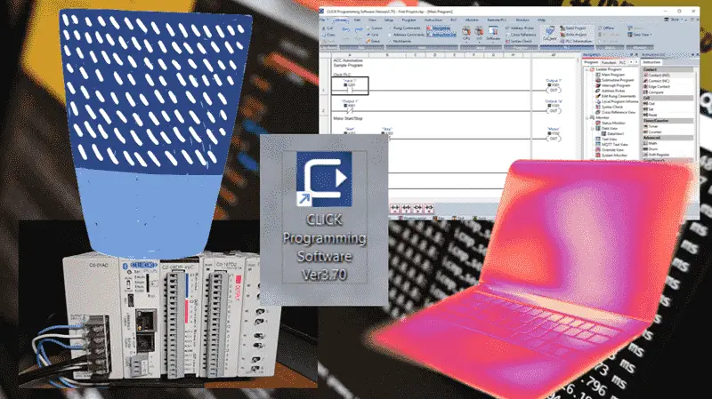
Previously, we installed the Click PLC Programming Software, updated the Firmware on the Click PLUS PLC, and created a sample program to test the inputs and outputs.
Video: FREE CLICK PLC Software: Is It REALLY That Easy?
Our entire Click series can be found here.
All of the previous information for the Click PLC can be applied to the Click PLUS.
The IP Configuration Protocol: A Practical Guide
Step 1: Initial Link-Up
First order of business: a direct shot. I ran a standard Ethernet cable straight from my router to the Click PLUS PLC.
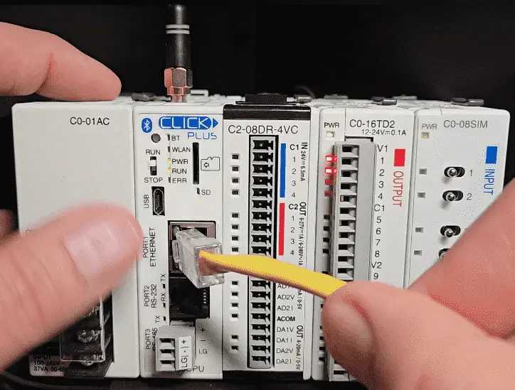
Port 1 of the Click PLC defaults to DHCP. Dynamic Host Configuration Protocol (DHCP) automates the assignment of IP addresses and other network configuration parameters to devices on the network. It’s the simplest way to establish that initial communication, especially with a factory-default device.
Step 2: Discovery and Access
Fired up the Click PLUS Programming Software. The Startup window automatically displays. The software feels intuitive. It knows that when I start this software, we will do one of three things. Start a new project, open an existing project, or connect to the PLC.
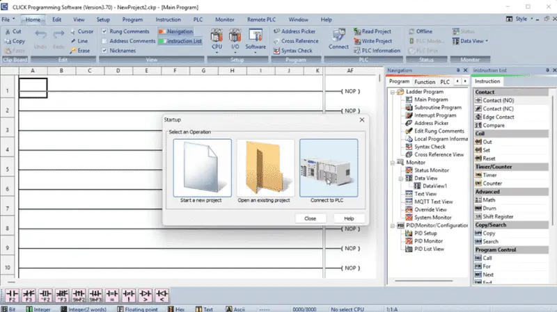
Select Connect to PLC.
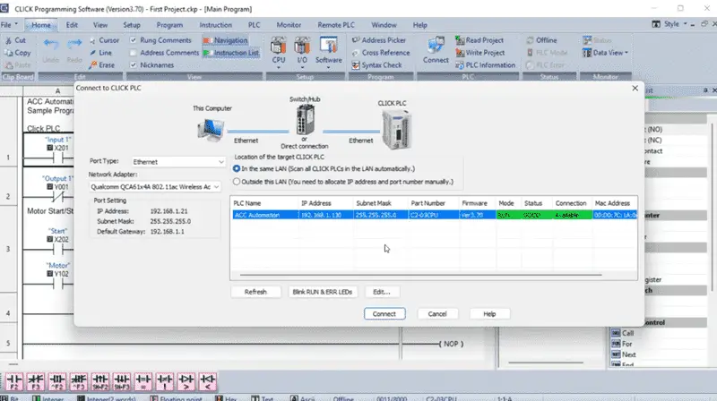
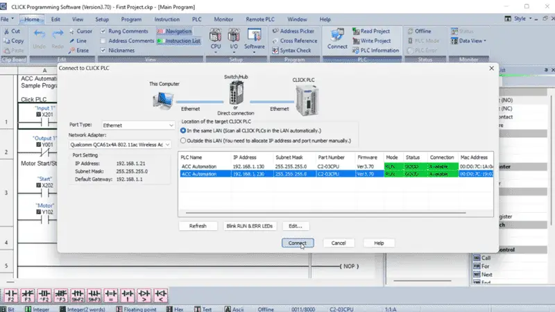
The Connect to CLICK PLC window will be displayed. This displays the PLC Name that we assigned previously.
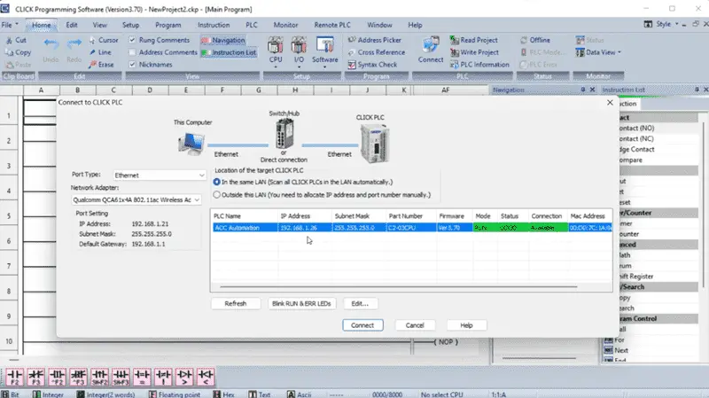
The software automatically initiated a network scan. Within seconds, the PLC’s default IP address (typically in the 192.168.1.x range, such as 192.168.1.26) populated the list. Confirmation of physical connectivity achieved. We also see the Firmware and physical MAC address of the controller.
IP addresses come in different classes. The standard default class is C.
| Class | Private IP Addresses |
| A | 10.0.0.0 – 10.255.255.255 |
| B | 172.16.0.0 – 172.31.255.255 |
| C | 192.168.0.0 – 192.168.255.255 |
The subnet mask is an essential setting on the network. All devices must have the same mask setting to communicate. Let’s make sure we write this down to ensure that the Class and Subnet Mask for our static (fixed) IP address will work.
Select Connect to establish communication with our CLICK PLUS PLC.
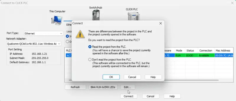
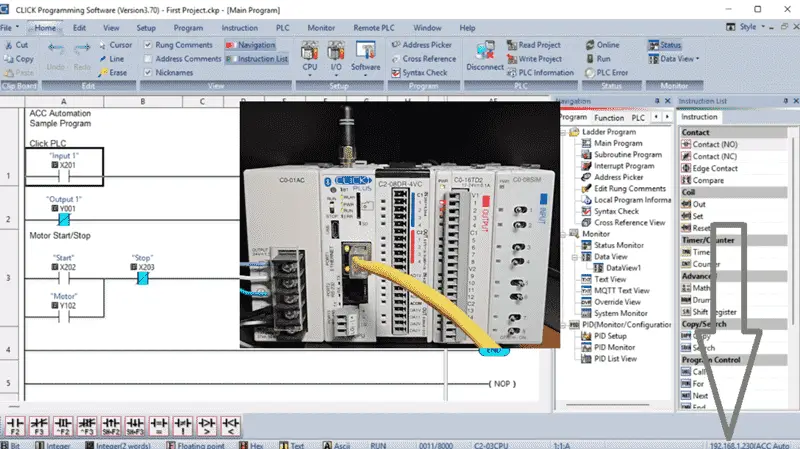
Select Read the Project from the PLC from the connect dialog window. Select OK. We can see that we are connected to the PLC along the bottom status bar of the Click PLC programming software.
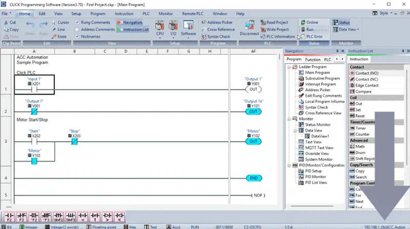
We are currently in RUN mode, and our previously created quick sample program is running.
Step 3: Assigning a Static IP: The Network Identity
Now for the main part: establishing a static IP address. Relying on DHCP in an industrial control environment is asking for trouble down the line. Network administrators can sometimes use reserved IP addresses based on the MAC address of the device. I like to set this to a static IP address anyway.
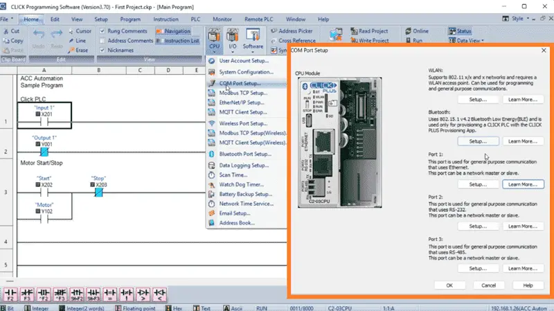
On the default home tab, select COM Port Setup under the CPU icon. This communication port setup window gives me the entire list of communication options. Select Port 1 Setup…
This is the Ethernet port with which we are currently communicating, as indicated on the bottom status line of the Click PLC Programming Software.
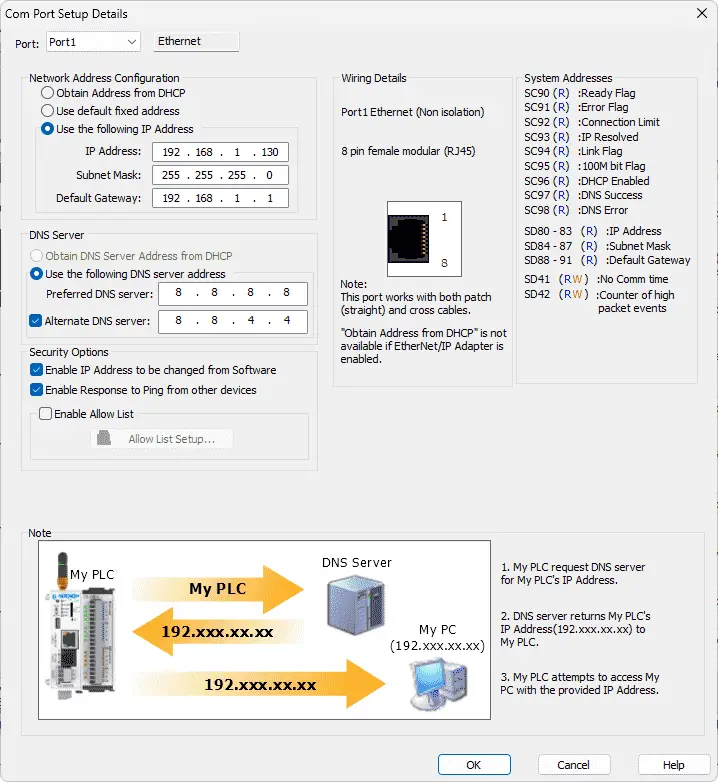
The COM Port Setup Details window is now displayed. Wow, this is very easy. Under the port, I can select any of the communication ports to set up.
Let’s enter the network parameters for Port1:
- Click IP Address: I punched in 192.168.1.130. This was chosen to fit neatly within the existing plant network’s designated subnet for automation devices, avoiding any potential conflicts.
- Subnet Mask: Standard 255.255.255.0. This defines the local network segment.
- Gateway Click IP Address: 192.168.1.1. This is the network’s router or Layer 3 switch, allowing the PLC to communicate beyond its immediate subnet if necessary (e.g., to an HMI on a different segment or a SCADA server).
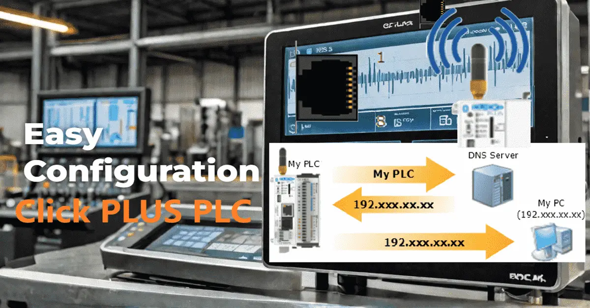
- DNS Server Address: 8.8.8.8. This Domain Name Server address will translate names into IP addresses. An example is ACCAutomation.ca.
- Alternative DNS Server Address: 8.8.4.4. This can improve browsing speed and enhance security.
I double-checked the entries. Looks solid. Select OK.
Step 4: Committing the Configuration
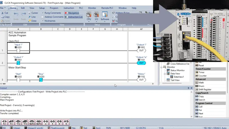
With the network parameters confirmed, I clicked “Write Project” on the Home tab. The software initiated the transfer, writing the new Click IP configuration directly to the PLC’s non-volatile memory.
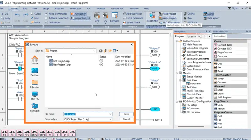
The software automatically recognizes that we need to save the program under the same name we used last time. Select Save.
The Select Network Settings window will now be displayed, as we have changed the settings.
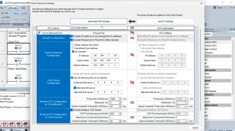
We can verify these settings again and then select Use Project File Settings.
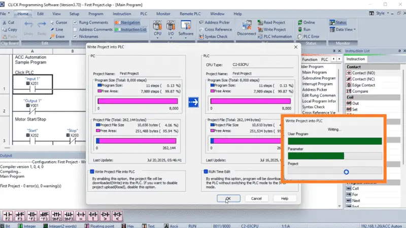
The Write Project into PLC window will be displayed. Select OK. We are executing a RUN time edit. This means that the PLC continues to run the program while the new program is being loaded. It then starts executing the new loaded program. This is done without pausing the PLC scan. Select Proceed RUN Time Edit. A “Transfer Completed” will appear in the Output window. Good.
Since changing the network settings that we were already using for communication, the software will error and return an offline status.
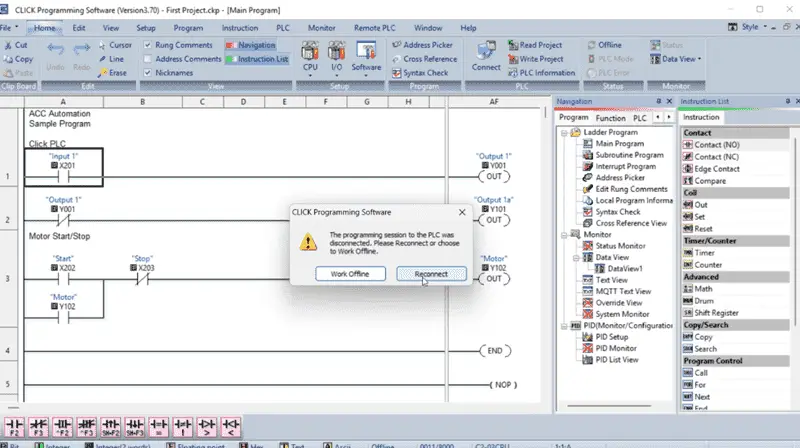
A warning message will be displayed indicating that the programming session to the PLC was disconnected. We can choose to work offline or select reconnect. Select Reconnect.
Step 5: Verifying Connectivity
Our Connect to CLICK PLC window will be displayed again. Wow, this programming software is very intuitive.
We can see our new set’s Click IP address. Select Connect.
In the Click software, I returned to Setup | Com Port Setup. This time, instead of Port 1, I selected the WLAN Setup… The Wireless Local Area Network Port parameters are displayed in the Com Port Setup Details window.
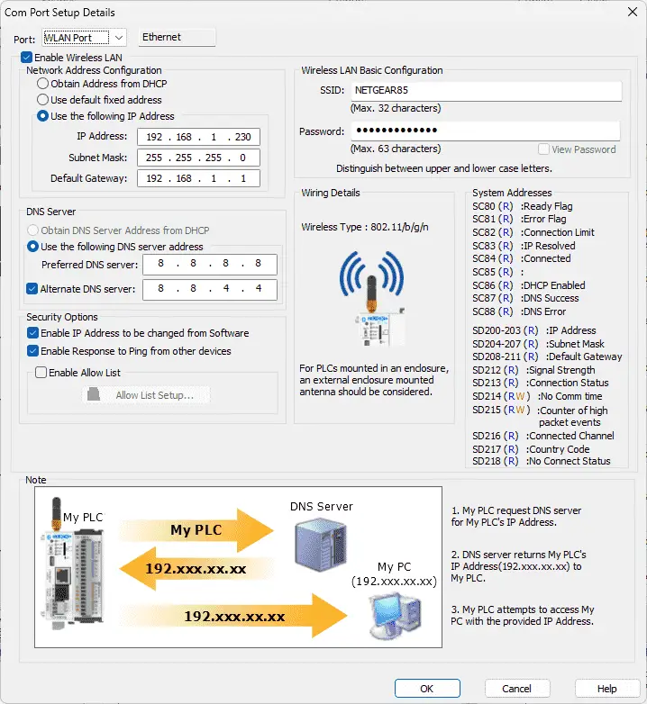
Select the Enable Wireless LAN option. This allows us to enter the static IP Address of 192.168.1.230 now. I quickly enter the SSID name of a Wi-Fi network that will enable devices to connect to it, along with the password.
Once again, we save and then transfer the program to the Click PLUS PLC.
Our WLAN light on the Click PLUS CPU comes to life. We are currently connected through Port 1. I select the Disconnect option on the Home tab. Selecting ‘Yes’ when asked if I want to disconnect from the PLC now shows our bottom line status as ‘Offline’.
Selecting Connect again will bring up the Connect to CLICK PLC.
This time, we can now see our two options for connection. Select our WiFi option and then select Connect. Our bottom status line will show our new connection. Success. The PLC was now officially an integrated component of the network, ready for programming and operational deployment.
This foundational step, while seemingly simple, is absolutely critical. Get the IP right, and the rest of the integration flows smoothly. Get it wrong, and you’ll be troubleshooting network issues before you even write your first rung of logic. On to the next phase.
Learn more about how to design, build, and program your own Click PLC system with confidence by clicking here. Click here to see how you can learn PLC programming using the Machine Simulator by Nirtec. This will provide machine scenes that you can program.
Download the Click PLC Programs here.
Watch on YouTube: Assign Static IP to CLICK PLUS PLC Easily!
Our entire series on the Click PLC can be found here.
The Click PLC can be programmed using free Click programming software from Automation Direct.
Here is a link to the software. Version 3.70
The entire Click PLC series before the Click PLUS release can be found here.
All previous posts and information are still valid with the Click PLC lineup.
YouTube Click Playlist
YouTube Click PLUS Playlist
Click and Click PLUS PLC Overview
Click and Click PLUS PLC Videos from Automation Direct
If you have any questions or require further information, please don’t hesitate to contact me.
Thank you,
Garry
If you’re like most of my readers, you’re committed to learning about technology. The numbering systems used in PLCs are not difficult to understand. We will walk through them, including Bits, Decimal, Hexadecimal, ASCII, and Floating Point.
To get this free article, subscribe to my free email newsletter.
Use the information to educate others on how numbering systems work.
Sign up now.

The ‘Robust Data Logging for Free’ eBook is also available as a free download. The link is included when you subscribe to ACC Automation.