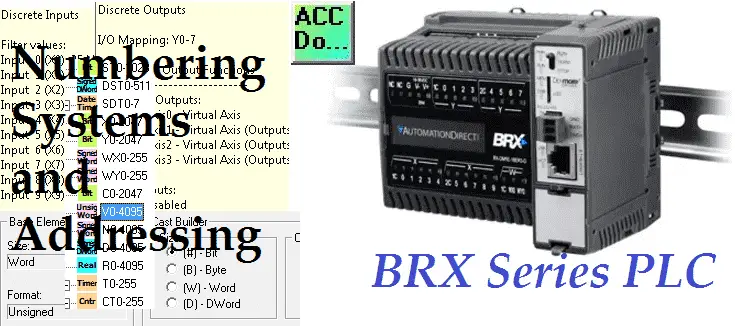
We will look at numbering systems in our BRX Do-More controller. This will include physical IO, casting, and indirect addressing. The BRX Do-More PLC like all of the PLCs in the Do-More Series use strong data typing. This means that there are fixed memory structures to work within your program. Errors will be displayed if you try to put the wrong type of value in the memory location. The data structures will automatically assist you in your automation system.
Memory can now be as flexible as you want and need. You can define and allocate all the data memory the way you want it up to specific maximums. As a system integrator, you determine what best fits your automation framework.
We will be looking at the addressing and numbering systems in the BRX Do-More Series PLC. Let’s get started.
Previously in this BRX Do-More series PLC, we have discussed:
System Hardware – Video
Unboxing – Video
Installing the Software – Video
Establishing Communication – Video
Firmware Update – Video
Addressing – BRX Do-More Numbering Systems
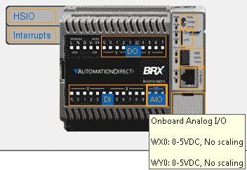
When we go online to our BRX Do-More PLC or develop a new project and select the controller, the dashboard will show us a picture of our controller.
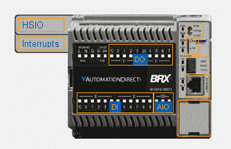
When we highlight the DI (Discrete Inputs) you will see the input number, address and filter value.
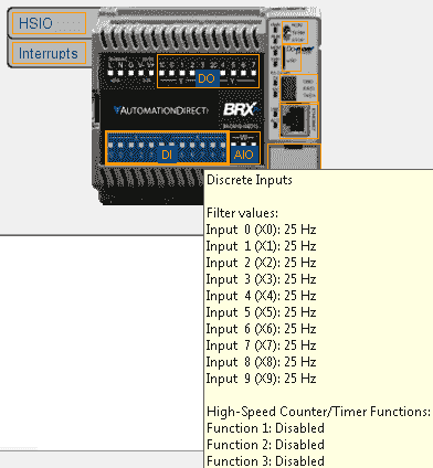
Input 0 (X0): 25 Hz
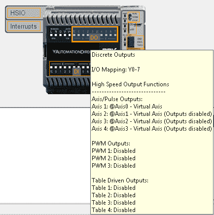
Similarly, when we highlight the DO (Discrete Outputs) you will see the output I/O Mapping (Y0 – Y7)
Highlight the AIO (Analog Input/Output) and it will show you the addressing for the analog signals.
Another way to view the I/O addresses is to use the system configuration window.
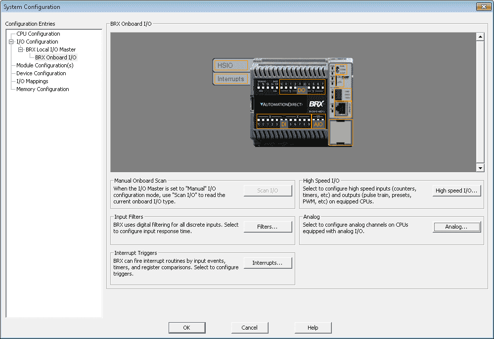
Here you can display the addresses and change the features of the I/O such as filters, Interrupts, and High-Speed I/O.
As mentioned before the BRX Do-More PLC uses strong data typing. These are called Data Blocks in the Do-More Controller. We have a number of built-in data blocks that are pre-configured, but we may change through the memory configuration window.
The following tables will give an overview of the data block areas.
System Status Bits / Values and Date / Time Structure – Numbering Systems
Note: System areas are not configurable. (Fixed)
| Data Block | Data Type | Default Range | Description |
| ST | Bit | ST0 – ST1023 | System Assigned Bits – Clock Flags etc. |
| DST | DWord | DST0-DST511 | System Assigned DWords – Scan Times etc. |
| SDT | Date / Time Structure | SDT0 – SDT7 | System Assigned Date / Time locations |
| UDT | Date / Time Structure | UDT0 – UDT31 | User Date / Time locations |
Physical Inputs and Outputs – BRX Do-More Numbering Systems
| Data Block | Data Type | Default Range | Description |
| X | Bit | X0 – X2047 | Discrete Inputs |
| Y | Bit | Y0 – Y2047 | Discrete Outputs |
| WX | Signed Word | WX0 – WX255 | Analog Inputs (-32768 to 32767) |
| WY | Signed Word | WY0 – WY255 | Analog Outputs (-32768 to 32767) |
| RX | Real (floating point) | RX0 – RX255 | Scaled Analog Inputs (-3.4e+038 to +3.4e+038) |
| RY | Real (floating point) | RY0 – RY255 | Scaled Analog Outputs (-3.4e+038 to +3.4e+038) |
Internal Bits and Numeric Values – BRX Do-More Numbering Systems
| Data Block | Data Type | Default Range | Description |
| C | Bit | C0 – C2047 | Control Relays |
| V | Unsigned Word | V0 – V4095 | 16 Bit Unsigned registers (0 to 65535) |
| N | Signed Word | N0 – N4095 | 16 Bit Signed registers (-32768 to 32767) |
| D | Signed DWord | D0 – D4095 | 32 Bit Signed registers (-2147483648 to 2147483647) |
| R | Real (floating point) | R0 – R4095 | 32 Bit Real registers (-3.4e+038 to +3.4e+038) |
Timers and Counters / Strings – BRX Do-More Numbering Systems
| Data Block | Data Type | Default Range | Description |
| T | Timer Structure | T0 – T255 | Timers |
| CT | Counter Structure | CT0 – CT255 | Counters |
| SL | String | SL0 – SL63 | Long Strings – 256 characters each |
| SS | String | SS0 – SS127 | Short Strings – 64 characters each |
Communications – Peerlink / KSequence Client(Master) / Modbus Client(Master)
| Data Block | Data Type | Default Range | Description |
| PL | Unsigned Word | PL0 – PL255 | Used to share data with PLC’s (Peerlink) |
| PL | Peerlink Structure | PL – Header | |
| DLX | Bit | DLX0 – DLX777 | KSequence – Octal – Referenced by ERM modules |
| DLY | Bit | DLY0 – DLY777 | KSequence – Octal – Referenced by ERM modules |
| DLC | Bit | DLC0 – DLC777 | KSequence – Octal – Referenced by ERM modules |
| DLV | Unsigned Word | DLV0 – DLV3777 | KSequence – Octal – Referenced by ERM modules |
| MI | Bit | MI1 – MI1023 | Modbus – Numbered in decimal |
| MC | Unsigned Word | MC1 – MC1023 | Modbus – Numbered in decimal |
| MIR | Bit | MIR1 – MIR2047 | Modbus – Numbered in decimal |
| MHR | Unsigned Word | MHR1 – MHR2047 | Modbus – Numbered in decimal |
Casting – BRX Do-More Numbering Systems
In the BRX Do-More Controller, there are three types of casting.
Extraction casts will isolate a bit, byte, or word from a larger element.
| Access Size | Syntax | Range | Description |
| Bit | :# | # = 0 to 7 (Bytes), 0-15 (Words), 0 to 31 (DWords) | Isolates a Bit from a Byte, Word, or DWord element |
| Byte | :B# | # = 0 to 1 (Words), 0 to 3 (DWords) | Isolates a Byte from a Word or DWord element |
| Word | :W# | # = 0 to 1 (DWords) | Isolates a Word from a DWord element |
Aggregation casts will group multiple elements into a larger element.
| Access Size | Syntax | Description |
| Byte | :B | Combines 8 bits into a Byte |
| Word | :W | Combines 16 bits or 2 Bytes into a Word |
| DWord | : D | Combines 32 bits, 4 Bytes, or 2 Words into a DWord |
Format casts will reinterpret the format of data in the element.
| Format | Syntax | Description |
| Unsigned Integer | :U | Reinterprets data as Unsigned Integer |
| Signed Integer | :S | Reinterprets data as Signed Integer |
| Real | :R | Reinterprets data as Floating Point |
Cast Builder – BRX Do-More Numbering Systems
The Do-More Designer software has a built-in cast builder that will help you in casing different elements. This is done by the Element Browser window. You can get to the Element Browser window by the main menu. Search | Element Browser… The short cut key is F9.
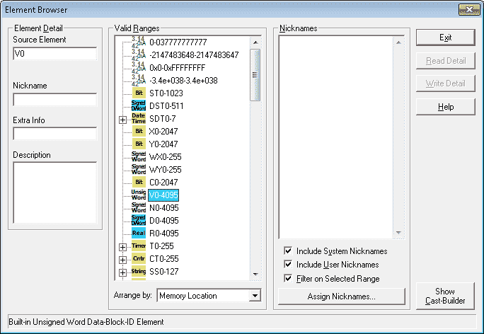
Hit the Show Cast-Builder button to show the cast builder.
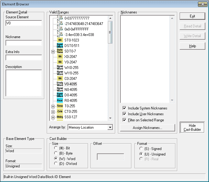
Let’s select the source element as V0. The picture above will automatically show you that V0 is a unsigned word. We will now select under the cast builder size (#) – Bit and under the offset 3. This means that we want the third bit in V0.
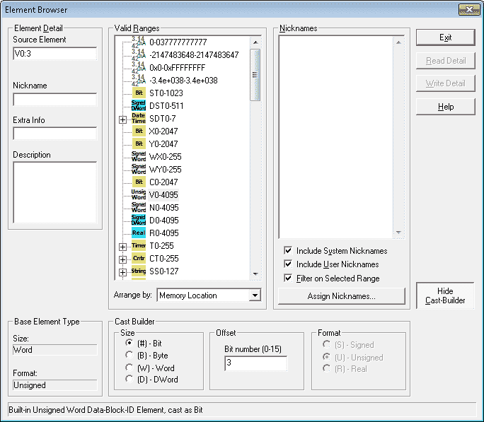
The result V0:3 specifies the bit that we are looking for in the word.
Now let’s take the same word and cast it as a DWord Real value. This means that our instruction will use V0 and V1.
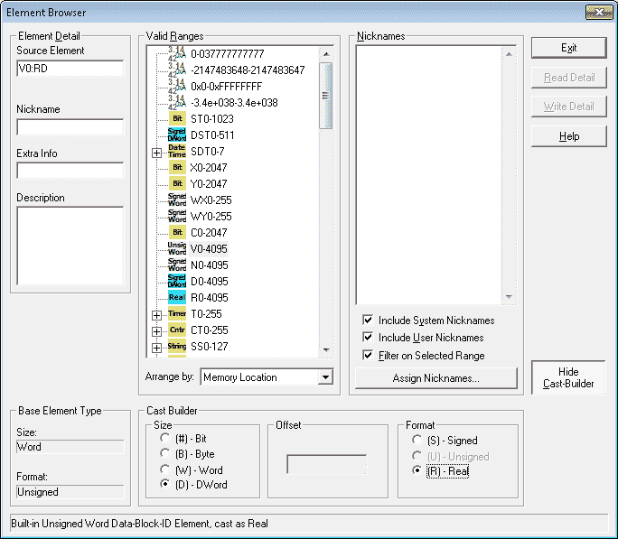
Our resulting cast is V0:RD.
Indirect Addressing – BRX Do-More Numbering Systems
Indirect addressing allows the memory addressed used by an instruction to be varied so that it can point to more than one location when running.
All of the data blocks in the CPU can be used as arrays. This includes the ones that you can define yourself. The array index must be in the range of 0 to 65535 and must be stored in the V memory location.
Example:
In this example, we are using V0 as the pointer in the array. Its value ranges from 1 to 6. We are using the instruction Move V[V0] to V100.
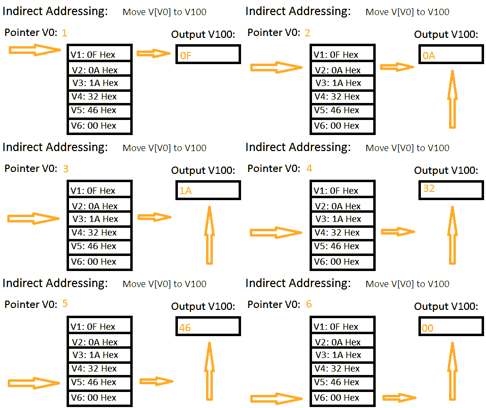
The following post have further information on indirect addressing:
HERE IS A METHOD THAT IS HELPING PLC PROGRAMMERS TO PROGRAM FASTER
BUILDING A PLC PROGRAM THAT YOU CAN BE PROUD OF
Creating Data Blocks (Tables) – BRX Do-More
Creating and modifying data blocks can be accomplished by the system configuration window. Main menu PLC | System Configuration… You can also hit the Configure symbol on the toolbar.
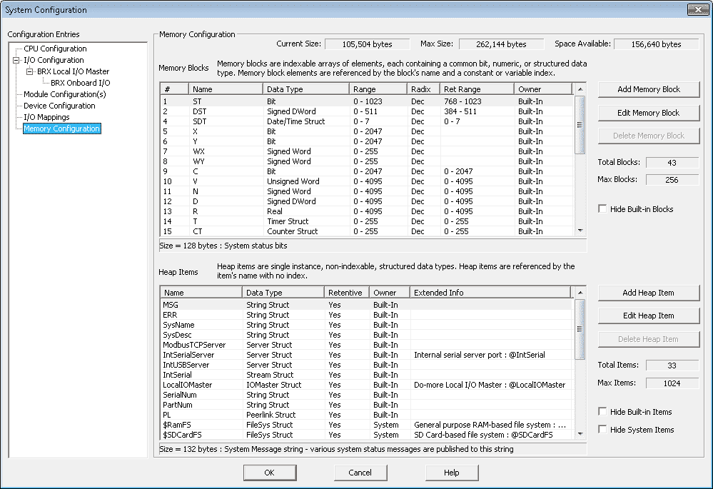
Let’s edit the C block of memory. Double click on the C block (#9) or click and select Edit Memory Block.
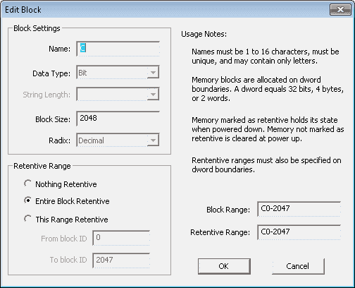
You can see the parameters for this block of memory. Let’s change the size of the block to 4095 and make them non-memory retentive.
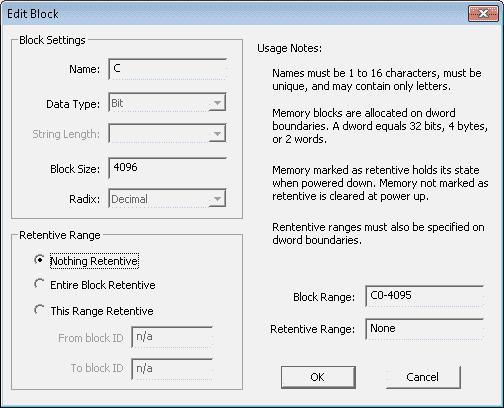
Once the parameters are changed select OK to save your configuration.
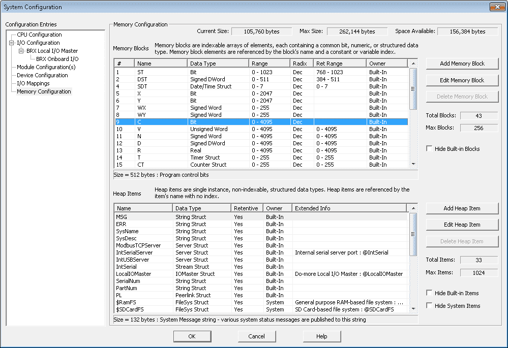
The modification of our memory block is complete.
To create a new memory block in our BRX Do-More controller, select the Add Memory Block button on the system configuration window.
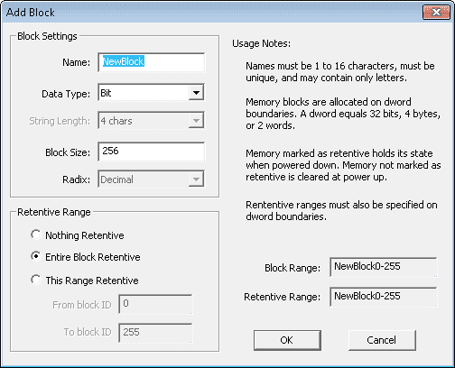
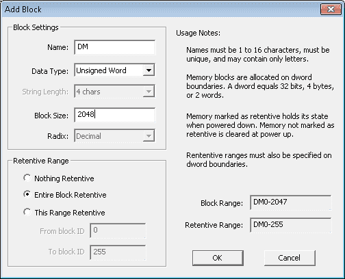
We can now put in the parameters that we want for our new memory block.
Name: DM
Data Type: Unsigned Word
Block Size: 2048
Entire Block Retentive – When power is removed from the PLC or the mode of the PLC changes from Run to Program, the information is retained.
We can now see our new block on the system configuration window.
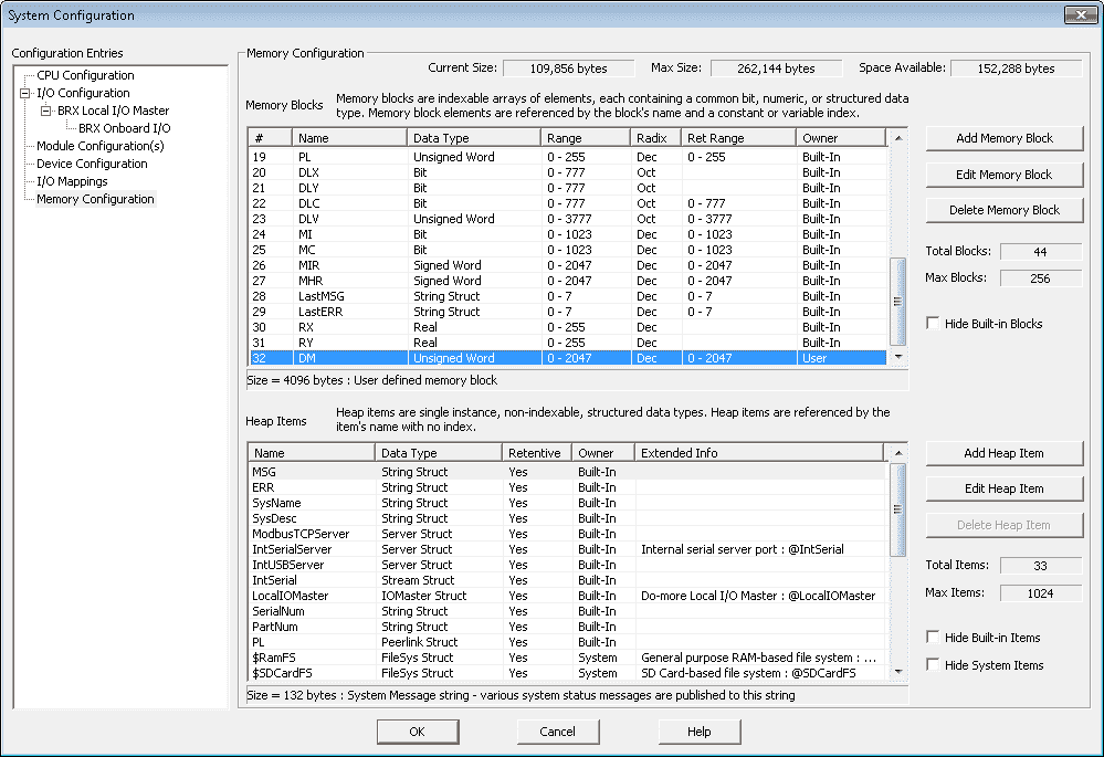
Changing and adding memory blocks is a great feature of this new BRX Do-More series PLC.
You can watch the video below to see the different numbering systems and addresses on the BRX Do-More Series PLC.
BRX Do-More Series PLC from Automation Direct – Power to deliver
Overview Link (Configure and purchase a system)
Manuals and Product Inserts (Installation and Setup Instruction)
Do-More Designer Software v2.0.3 (Free Download Link) – The software will contain all of the instruction sets and help files for the BRX Do-More Series PLC.
Next time we will look at our first program using the BRX PLC.
Watch on YouTube : BRX PLC Numbering Systems and Addressing
If you have any questions or need further information please contact me.
Thank you,
Garry
If you’re like most of my readers, you’re committed to learning about technology. Numbering systems used in PLC’s are not difficult to learn and understand. We will walk through the numbering systems used in PLCs. This includes Bits, Decimal, Hexadecimal, ASCII and Floating Point.
To get this free article, subscribe to my free email newsletter.
Use the information to inform other people how numbering systems work. Sign up now.
The ‘Robust Data Logging for Free’ eBook is also available as a free download. The link is included when you subscribe to ACC Automation.

