We will now look at program control in the BRX Do-More controller. The program control instructions will allow us to specify what parts of the logic get solved and when this happens. This will control how the PLC will scan and solve your logic in your program using a synchronous PLC Scan. Understanding the PLC program scan will explain the synchronous and asynchronous program scanning. Ladder logic programs get solved left to right, top to bottom. The result of the rung before is available for the next rung.
Using programs, tasks, and subroutines in our BRX Do-More Series PLC we can divide up our program into smaller segments. This will help when we troubleshoot the system in the field as the system integrator. Let’s look at some samples of each of the above-mentioned methods.
Previously in this BRX Do-More series PLC, we have discussed:
System Hardware – Video
Unboxing – Video
Installing the Software – Video
Establishing Communication – Video
Firmware Update – Video
Numbering Systems and Addressing – Video
First Program – Video
Monitoring and Testing the Program – Video
Online Editing and Debug Mode – Video
Timers – Video
Counters – Video
High-Speed IO – Video
Compare Instructions – Video
Math Instructions – Video
Tasks – BRX Do-More Program Control
Tasks are code blocks that can be individually enabled to run as part of the current PLC scan. They can be used as a single pass through the ladder logic one time or you can execute at a specific interval.
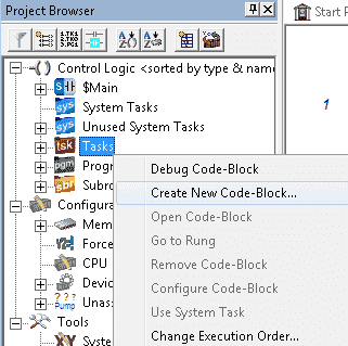
To create a new task, right click on the tasks menu in the Project Browser. You will then see a menu that you can Create New Code-Block…
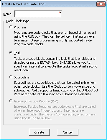
The task will be selected as the default Code-Block type. Select Create.
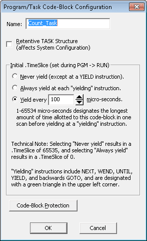
You will now get the Program/Task Code-Block Configuration window. This window will allow you to set the Retentive TASK Structure. This means that the information in the memory area assigned to your task will be memory retentive. The values will be remembered if power is removed from the PLC or the PLC is placed back into run mode after being in program mode.
Initial TimeSlice is the setting to determine how the task will be executed. We will leave this as 100 microseconds. This means that after 100 microseconds the task will stop (yield) and allow other code to execute in the scan. On the next scan, the task will continue executing the code. This cycle will repeat until the task has been completed. Our overall scan time remains consistent because of this yielding of the task.
You will also notice that we can turn on code-block protection. This will enable us to input a password in order to view or modify the code. (PLC programming rungs)
Select OK.
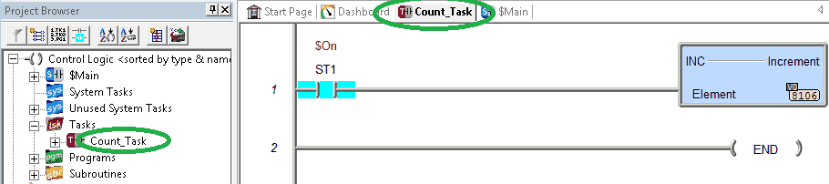
We can now enter our programming rungs in the Count_Task program that we have created. Our program will increment V0 by one each time the task is executed.
Select the Main program.
To call our task we use the instruction ENTASK (Enable Task).
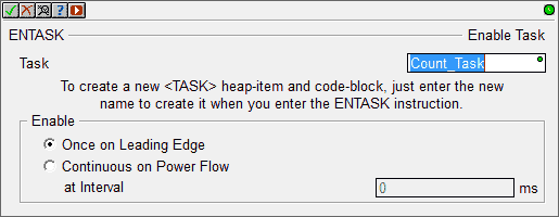
We specify the task to enable. If this is a new task name, then a task will be created for us and we can then program the code later. In our case, this will be the Count_Task that we have just programmed. We will also specify to enable the task once on the leading edge.
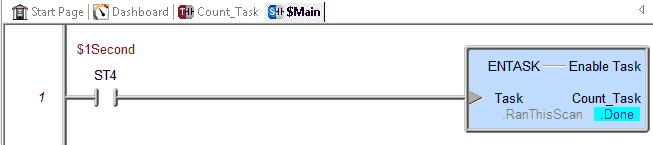
The one-second system clock bit will enable our task. This means that memory location will increment by 1 every one second.
Program – BRX Do-More Program Control
Program code blocks Programs are executed by using the Run Program (RUN) instruction. Once a Program has been started, it will run every controller scan until an Exit This Program (EXIT) instruction within the Program itself is executed, another Program or Task executes a Halt Program or Task (HALT) or a Restart Program or Task (RESTART) instruction that targets the Program.
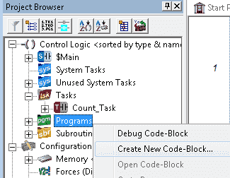
To create a new program, right-click on the Programs menu in the Project Browser. You will then see a menu that you can Create New Code-Block… You can also use a RUN (Run Program) instruction and specify a name. This will also create a new code block.
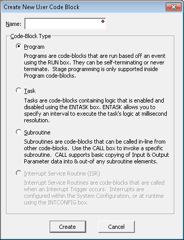
The program will be selected as the default Code-Block type. Select Create.

We now have the Program/Task Code-Block Configuration window showing. This is identical to the Task code block configuration above. We will leave everything at the default value with no Code-Block Protection.
Select OK.
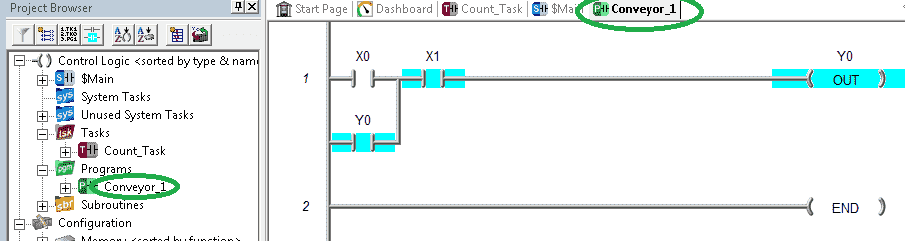
Program rungs can now be entered into the Conveyor_1 program code-block. This is a simple stop / stop circuit.
Select the main program. We will now call the RUN (Program Run) instruction to execute this new program called Conveyor_1.
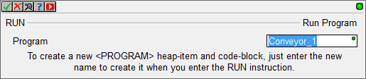
If the name for the program was new it would automatically call up a new program code block for us to use.
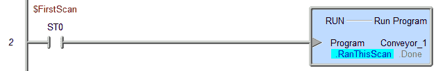
Our code in the Main program will call the RUN instruction using the first scan system bit. This will execute when power is applied to our PLC or we transition to run mode. The program will continue to execute until we get a stop (halt) command mentioned above.
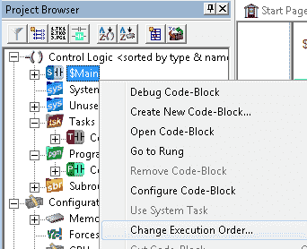
Changing the execution order of our Main, Task (Count_Task), and Program (Conveyor_1) can be done by right-clicking on any of the items in the project browser and selecting Change Execution Order…
We can then select the item from the Modify Execution Order window and use the Move Up and Move Down button.
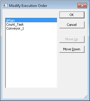
The order of execution will be Main, Count_Task and then Conveyor_1 if the task and program are enabled to run.
Select OK to close this window.
Subroutines – BRX Do-More Program Control
Subroutines are code-blocks that are invoked through the Call Subroutine (CALL) instruction. The ladder logic in a Subroutine is executed at the point in time the Call instruction is executed, and all of the ladder logic in a subroutine is executed each time the subroutine is invoked. Subroutines are typically used when there is ladder logic that needs to be executed multiple times with a different set of input and/or output values each time it is executed. A subroutine can execute another instance of itself from within that Subroutine up to 84 levels deep.
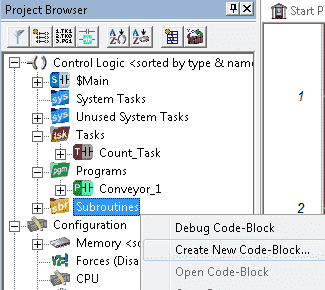
To create a new subroutine, right-click on the Programs menu in the Project Browser. You will then see a menu that you can Create New Code-Block…
The subroutine will be selected as the default Code-Block type. Select Create.
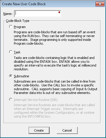
The Subroutine Code-Block Configuration window will only have a code block protection option. This is because subroutines will always execute to the end of the subroutine code.
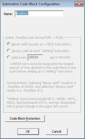
Select OK.
You will notice that the RET (Return Back to CALL) instruction will automatically be in the subroutine ladder rung. This instruction must appear on the last line of the subroutine. The subroutine can also use the RETC (Conditional Return Back to Call) if you wish to end the subroutine before its final ending point.
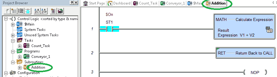
Our sample program will use the MATH instruction to add V1 to V2 and store the result in V3. The always on system bit is the condition for the math instruction.
Select the Main program. We will now use the CALL instruction to execute our subroutine.
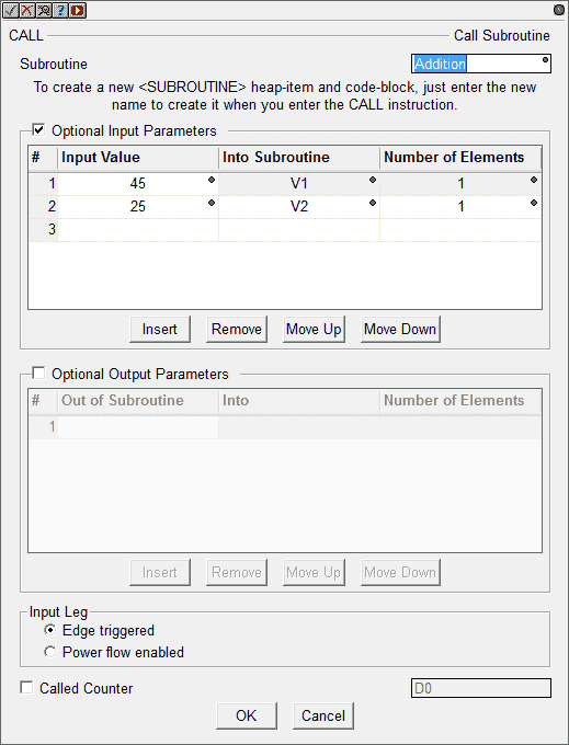
Using the Optional Input Parameters we will have input numbers 45 and 25 go into V1 and V2. Our call to the subroutine will be edge-triggered.
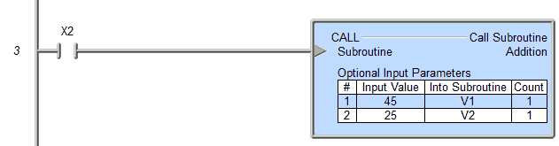
X2 will be the input condition to call our subroutine from the main program. When the input is enabled, 45 will be added to 25 and 70 will be placed into our output V3.
We will now call the same subroutine again using different parameters.
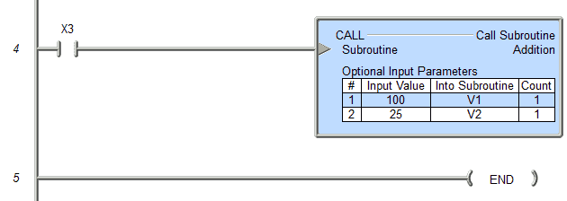
X3 will be the input condition to call our subroutine from the main program. 100 is added to 25 and the result 125 is placed into output V3 each time the input is enabled.
You can see the power of using subroutines for repeated code with different parameters.
Note: One other program control feature is the ISR (Interrupt Service Routines). An interrupt is a signal generated by some event external to the CPU, which causes the CPU to stop what it is doing and jump to a separate piece of code designed by the programmer to deal with the event which generated the interrupt request. This interrupt handling code is called an ISR (interrupt service routine). When the ISR is finished, the CPU returns to the code that was running prior to the interrupt. In the Do-more CPUs, an interrupt service routine (ISR) is a code-block, whose execution is triggered by the reception of an Interrupt Trigger, which is configured through the System Configuration or through the INTCONFIG – Interrupt Configuration Editor. Interrupt Triggers define the external hardware event or timed event that constitutes the Interrupt, and associates an Interrupt Service Routine (ISR) that will be executed when that Interrupt Trigger is fired.
Controlling our program is easy with programs, subroutines, and tasks. The advantage is that our program will also be easier to read, understand and troubleshoot. More information can be obtained from the Do-More Designer Software help files. You can also get more information in the manuals listed below.
You can watch the video below to see how the program control works in the BRX Do-More Series PLC.
You can download the program here.
BRX Do-More Series PLC from Automation Direct – Power to deliver
Overview Link (Configure and purchase a system)
Manuals and Product Inserts (Installation and Setup Instruction)
Do-More Designer Software v2.0.3 (Free Download Link) – The software will contain all of the instruction sets and help files for the BRX Do-More Series PLC.
Next time we will look at shift registers in the BRX Do-More PLC.
Watch on YouTube: BRX Do-More PLC Program Control
If you have any questions or need further information please contact me.
Thank you,
Garry
If you’re like most of my readers, you’re committed to learning about technology. Numbering systems used in PLC’s are not difficult to learn and understand. We will walk through the numbering systems used in PLCs. This includes Bits, Decimal, Hexadecimal, ASCII and Floating Point.
To get this free article, subscribe to my free email newsletter.
Use the information to inform other people how numbering systems work. Sign up now.

The ‘Robust Data Logging for Free’ eBook is also available as a free download. The link is included when you subscribe to ACC Automation.