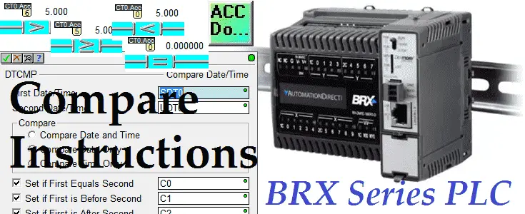
Compare instruction is often used in PLC programs to test pairs of values. The output of this comparison conditions the logical continuity of a rung. The BRX Do-More series of programmable logic controllers have the following compare contact instructions.
= (if Equal contact)
<> (if Not Equal contact)
> (if Greater Than contact)
>= (if Greater Than or Equal contact)
< (if Less Than contact)
<= (if Less Than or Equal contact)
Besides this instruction, the BRX Do-More PLC will also have to compare instructions for the built-in real-time clock of the system. We will be looking at these instructions along with some programming examples. As a system integrator, this ability can prove very useful to you in the field when commissioning your automation system.
Let’s get started with the BRX Do-More PLC Compare Instructions.
Previously in this BRX Do-More series PLC, we have discussed:
System Hardware – Video
Unboxing – Video
Installing the Software – Video
Establishing Communication – Video
Firmware Update – Video
Numbering Systems and Addressing – Video
First Program – Video
Monitoring and Testing the Program – Video
Online Editing and Debug Mode – Video
Timers – Video
Counters – Video
High-Speed IO – Video
The best way to learn about the compare contact bits is to look at an example. We will set up a counter that has the system 1-second flag as the count input. Our preset value will be set to 10. The counter will be self-resetting by placing the counter done bit into the reset input. Using the contact compare instructions we will now turn on/off the physical outputs as appropriate. Please refer to the post: BRX Do-More PLC Counters for a review of counters in the PLC.

The accumulator of the counter CT0.ACC will contain the current value of the counter. This will cycle from 0 to 10, 0 to 10, etc. Let’s now look at the contact compare instructions.
(CONTACT) – if Equal – BRX Do-More Compare Instructions

When the value of CT0.ACC is equal to 0 then the contact is closed allowing power flow to turn on Y0 output. When the value of CT0.ACC is not equal to 0 then the contacts are open, interrupting power flow.
(CONTACT) – If Not Equal – BRX Do-More Compare Instructions

When the value of CT0.ACC is not equal to 0 then the contact is closed allowing power flow to turn on Y1 output. When the value of CT0.ACC is equal to 0 then the contacts are open, interrupting power flow.
(CONTACT) – If Greater Than – BRX Do-More Compare Instructions

When the value of CT0.ACC (left side) is greater than 5 (right side) then the contact is closed allowing power flow to turn on Y2 output. When the value of CT0.ACC is less than or equal to 5 then the contacts are open, interrupting power flow.
(CONTACT) – If Greater Than or Equal – BRX Do-More Compare Instructions

When the value of CT0.ACC (left side) is greater than or equal to 5 (right side) then the contact is closed allowing power flow to turn on Y3 output. When the value of CT0.ACC is less than 5 then the contacts are open, interrupting power flow.
(CONTACT) – If Less Than – BRX Do-More Compare Instructions

When the value of CT0.ACC (left side) is less than 5 (right side) then the contact is closed allowing power flow to turn on Y4 output. When the value of CT0.ACC is greater than or equal to 5 then the contacts are open, interrupting power flow.
(CONTACT) – If Less Than or Equal – BRX Do-More Compare Instructions

When the value of CT0.ACC (left side) is less than or equal to 5 (right side) then the contact is closed allowing power flow to turn on Y5 output. When the value of CT0.ACC is greater than 5 then the contacts are open, interrupting power flow.
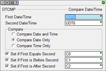
DTCMP – Compare Date / Time – BRX Do-More Compare Instructions
The Compare Date / Time (DTCMP) instruction compares the Date and/or Time fields of two Date / Time structures. The comparison operation subtracts the second date/time from the first date/time.

In our example, we will use the system date and time (SDT0) and compare this to the user-defined date and time structure. (UDT0) Comparing the date only we will set the bits C0 to C2 according to the compare results.

This instruction can be used to set up a regular maintenance schedule for the equipment that you are programming.
DTDIFF – Difference between two Date / Times – BRX Do-More Compare Instructions
The Difference between two Date / Times (DTDIFF) instruction calculates the number of seconds of time between the contents of two Date / Time structures.

In our example, we will use the system date and time (SDT0) and compare this to the user-defined date and time structure. (UDT0) The result is the number of seconds difference between the two dates.

This can be used for an indication of the time before the next preventative maintenance that is due on the machine.
You can watch the video below to see how ‘compare instructions’ work in the BRX Do-More Series PLC.
You can download the program here.
BRX Do-More Series PLC from Automation Direct – Power to deliver
Overview Link (Configure and purchase a system)
Manuals and Product Inserts (Installation and Setup Instruction)
Do-More Designer Software v2.0.3 (Free Download Link) – The software will contain all of the instruction sets and help files for the BRX Series PLC.
Next time we will look at the math instruction in the BRX PLC.
Watch on YouTube: BRX PLC Compare Instructions
If you have any questions or need further information please contact me.
Thank you,
Garry
If you’re like most of my readers, you’re committed to learning about technology. Numbering systems used in PLC’s are not difficult to learn and understand. We will walk through the numbering systems used in PLCs. This includes Bits, Decimal, Hexadecimal, ASCII and Floating Point.
To get this free article, subscribe to my free email newsletter.
Use the information to inform other people how numbering systems work. Sign up now.
The ‘Robust Data Logging for Free’ eBook is also available as a free download. The link is included when you subscribe to ACC Automation.


