A majority of the programmable logic controller (PLC) programs will include a counter instruction. The BRX Do-More series of programmable logic controllers have several different counters available for your program. There are five different basic counter instructions in the PLC. The memory area for counters (CT) includes the Counter PVs (Present Values) Counter SVs (Set Values) and the Counter Completion Flags. The default size of the counter area is CT0 – CT255. This size can change to the amount that we need for our program. Please see BRX Do-More PLC Numbering Systems and Addressing on how to change the memory configuration of the controller.
We will be looking at the counter instructions in the BRX Do-More PLC along with some programming examples. As a system integrator, this ability can prove very useful to you in the field when commissioning your automation system. When dealing with counters, we need to look at timing charts. The Secret of Using Counters is a good refresher on using timing charts.
Let’s get started with the BRX Do-More PLC Counters.
Previously in this BRX Do-More series PLC, we have discussed:
System Hardware – Video
Unboxing – Video
Installing the Software – Video
Establishing Communication – Video
Firmware Update – Video
Numbering Systems and Addressing – Video
First Program – Video
Monitoring and Testing the Program – Video
Online Editing and Debug Mode – Video
Timers – Video
Instruction Flags – BRX Do-More Counters
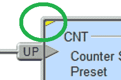
Do-More Designer uses differently colored triangles in the upper left corner to show you how the instruction is used. All of the instructions that we will be discussing have a yellow (Multi-scan) symbol.

The multi-scan designates an instruction that will take two or more PLC scans to complete. These instructions depend on the status of the instruction from the previous scan to properly function during the current scan. This just provides some additional information when looking at the instructions.
CNT – Up Counters – BRX Do-More

The up-counter uses two inputs. When the first input (X0) transitions from off to on, the accumulator will increment by 1. Once the accumulator has reached the set value, the counter done bit will be set. The second input (X1) is the reset for the counter. The accumulator will return to zero.
CNTDN – Down Counters – BRX Do-More

The down counter is similar to the up counter except that the accumulator will decrement from the set value down to zero.
Note: This is the exact same timing chart as the up timer above.
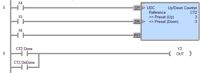
UDC – Up/Down Counters – BRX Do-More

The up / down counter has three inputs. The first input will increment the accumulator by one with a transition from off to on. The second input will decrement the accumulator by one with a transition from off to on.
If no set values are programmed then the Done bit is set when the accumulator is positive and the DnDone bit is set when the accumulator is negative. In our example, the Done bit will be set with an accumulator greater or equal to 3. The DnDone bit will be set with an accumulator less than or equal to -3.
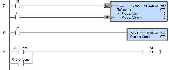
UDCG – Global Up/Down Counters – BRX Do-More

The global up / down counter is similar to the UDC up / down counter, except that it does not have a reset input.
The reset is achieved by the RSTCT reset counter instruction.
Note that you can have no set value, a preset up value, a preset down value, or both a preset up and down value.
You can watch the video below to see how the different counter instructions work in the BRX Do-More Series PLC.
You can download the program here.
BRX Do-More Series PLC from Automation Direct – Power to deliver
Overview Link (Configure and purchase a system)
Manuals and Product Inserts (Installation and Setup Instruction)
Do-More Designer Software v2.0.3 (Free Download Link) – The software will contain all of the instruction sets and help files for the BRX Do-More Series PLC.
Next time we will look at high speed I/O in the BRX Do-More PLC.
Watch on YouTube: BRX Do-More PLC Counters
If you have any questions or need further information please contact me.
Thank you,
Garry
If you’re like most of my readers, you’re committed to learning about technology. Numbering systems used in PLC’s are not difficult to learn and understand. We will walk through the numbering systems used in PLCs. This includes Bits, Decimal, Hexadecimal, ASCII, and Floating Point.
To get this free article, subscribe to my free email newsletter.
Use the information to inform other people how numbering systems work. Sign up now.
The ‘Robust Data Logging for Free’ eBook is also available as a free download. The link is included when you subscribe to ACC Automation.


