A majority of the programmable logic controller (PLC) programs will include a timer instruction. The BRX Do-More series of programmable logic controllers have several different timers available for your program. There are nine different basic timing instructions in the PLC. The memory area for timers includes the Timer PVs (Present Values) Timer SVs (Set Values) and the Timer Completion Flags. The default size of the timer area is T0 – T255. This size can change to the amount that we need for our program. Please see BRX Do-More PLC Numbering Systems and Addressing on how to change the memory configuration of the controller.
We will be looking at the timer instructions in the BRX Do-More PLC along with some programming examples. As a system integrator, this ability can prove very useful to you in the field when commissioning your automation system. When dealing with timers, we need to look at timing charts. The Secret of Using Timers is a good refresher on using timing charts.
Let’s get started with the BRX Do-More PLC Timers.
Previously in this BRX Do-More series PLC, we have discussed:
System Hardware – Video
Unboxing – Video
Installing the Software – Video
Establishing Communication – Video
Firmware Update – Video
Numbering Systems and Addressing – Video
First Program – Video
Monitoring and Testing the Program – Video
Online Editing and Debug Mode – Video
Instruction Flags – BRX Do-More
Do-More Designer uses differently colored triangles in the upper left corner to show you how the instruction is used. All of the instructions that we will be discussing have a yellow (Multi-scan) symbol.
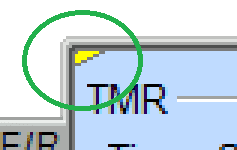
The multi-scan designates an instruction that will take two or more PLC scans to complete. These instructions depend on the status of the instruction from the previous scan to properly function during the current scan. This just provides some additional information when looking at the instructions.
TMR – Up Timers – BRX Do-More

When the input is off the timer is reset. When the input is on the timer will time up for the set amount of time. (5 seconds) After the time expires the done bit will turn on causing the output to turn on. This has the timing chart of an on delay timer.

TMRDOWN – Down Time – BRX Do-More

When the input is off the timer is reset. When the input is on the timer will time down for the set amount of time. (5 seconds) After the time expires the done bit will turn on causing the output to turn on.
Note: This is the exact same timing chart as the up timer above.
TMRA – Accumulating Up Timers – BRX Do-More

When X2 is on the time accumulates. When X2 is off the time accumulation stops. After the time accumulation reaches the set point the done bit of the timer will turn on. The reset will happen when the input X3 is turned on. The timing chart is an on delay as well. We just have a separate input for the reset.
TMRADOWN – Accumulating Down Timers – BRX Do-More

When X4 is on the time accumulates downward. When X4 is off the time accumulation stops. After the time accumulation reaches the set point the done bit of the timer will turn on. The reset will happen when the input X5 is turned on.
TMRAG – Global Accumulating Timers – BRX Do-More
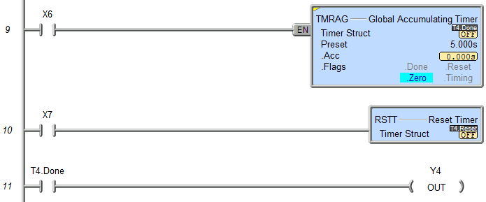
The global accumulating timer is similar to the accumulating up timer except that the reset is a separate instruction. (RSTT) Reset Timer
When the timer times out the done bit is set for the timer number.
OFFDTMR – Off Delay Timers – BRX Do-More
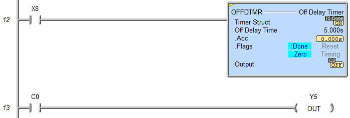
When the input turns on the output bit C0 also turns on. The off delay timer times when the input turns off. The output bit will remain on for the timed value.
This is the off delay timing chart.

ONDTMR – On Delay Timers – BRX Do-More
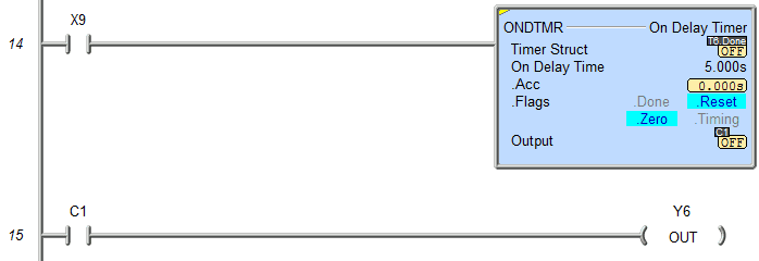
The on delay timer will delay the output from coming on for the set time interval if the input is on. If the input condition goes off, the timer resets.
FREQTMR – Frequency Timers – BRX Do-More

The frequency timer will calculate the counts per second, minute, or hour that input is coming on/off. There is a filter constant that can be used on the output during the calculations. The output is a real number. The instruction also has a built-in scale that we can scale our output to a meaningful value.
Example: $100ms pulse bit = 10 times per second x 60 = 600 times per minute
You can download the program here.
You can watch the video below to see how the different timer instructions in the BRX Do-More Series PLC.
BRX Do-More Series PLC from Automation Direct – Power to deliver
Overview Link (Configure and purchase a system)
Manuals and Product Inserts (Installation and Setup Instruction)
Do-More Designer Software v2.0.3 (Free Download Link) – The software will contain all of the instruction sets and help files for the BRX Do-More Series PLC.
Next time we will look at counters in the BRX Do-More PLC.
Watch on YouTube: BRX Do-More PLC Timers
Note:
There has been an update to the BRX Do-More PLC. Do-More Update release 2.1.
They have also added AB/Rockwell Timer bit fields – .TT (Timer Timing), .DN (Done), .EN (Enable) These bits will behave just like the AB Timers. The behavior of the existing Do-More Timer bits has not changed. This will make those familiar with Allen Bradley timer programming more comfortable with the Do-More Designer programming.
The Common Timer Instruction Editor has also been added. It provides details about the behavior of each different Timer instruction in the Do-more control engine. The editor comes up by default when you create any new Timer instruction (TMR, TMRA, ONDTMR, OFFDTMR, TMRDOWN, TMRADOWN, TMRAG)
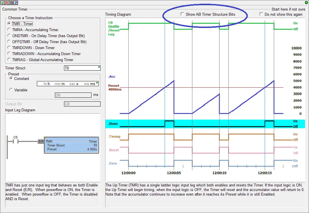 As you cycle through the different Timer instruction radio buttons in the top/left, the Input Leg and Timing diagram descriptions change, providing details about that specific Timer instruction. This makes it easy to see the differences between the various Timer instructions, giving you the information you need to choose the best Timer for the task at hand. This release of the software has many new features like the ones above. You can download the newest version of the software free of charge here: http://support.automationdirect.com/products/domore.html
For additional updated features, please refer to the updates.pdf file in the installation folder.
If you have any questions or need further information please contact me.
Thank you,
Garry
If you’re like most of my readers, you’re committed to learning about technology. Numbering systems used in PLC’s are not difficult to learn and understand. We will walk through the numbering systems used in PLCs. This includes Bits, Decimal, Hexadecimal, ASCII and Floating Point.
To get this free article, subscribe to my free email newsletter.
Use the information to inform other people how numbering systems work. Sign up now.
The ‘Robust Data Logging for Free’ eBook is also available as a free download. The link is included when you subscribe to ACC Automation.

