The Machine Simulator (MS) is part of the EasyPLC software suite. It has many built-in machines that can be programmed. The box selection (camera management and distribution) is one of these machines. It will read barcodes from the boxes and send them to different exit ramps. The Do-More Designer PLC Simulator will be used to program this virtual machine.
We will connect the simulator to the box selection machine using the Do-More Designer PLC software. This will be done using Modbus TCP (Ethernet) for communications. Using the five steps for program development, we will show how this is programmed. Let’s get started.
The Machine Simulator (MS) is part of the EasyPLC Software Suite. This is a complete PLC, HMI, and Machine Simulator Software package. This PLC learning package includes a Machine Simulator (MS). This virtual 3D world with real-time graphics and physical properties can communicate with several programmable logic controllers. (PLC) See below to receive a 10% discount on this PLC learning package. Invest in yourself today.
Previously, we have done the following:
Easy PLC Installing the Software – Video
Click PLC – Easy Transfer Line Programming – Video
Productivity PLC Simulator – Chain Conveyor MS – Video
Define the task: (Step 1 – Box Selection)
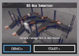
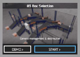
The machine simulator has a demo mode for the built-in machines. This will allow you to watch the operation of the box selection. This will help you see what has to be done.
There is also a written version of the sequence on the left-hand side of the machine.
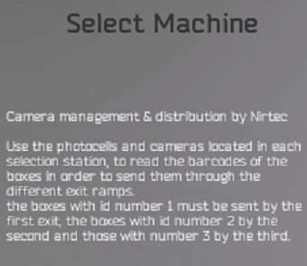
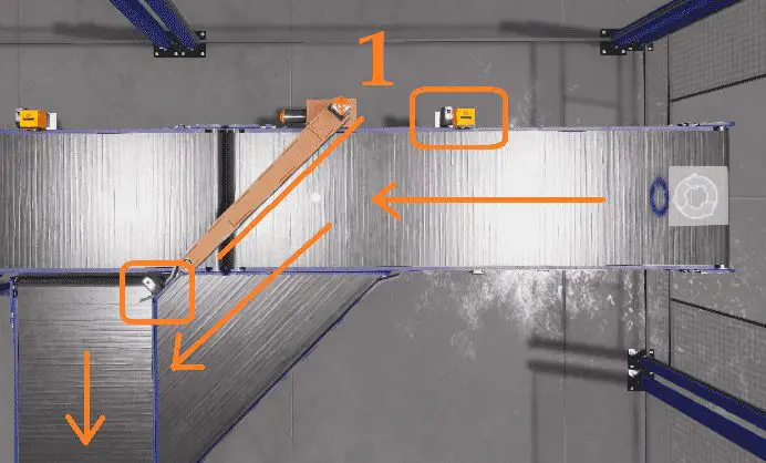
Camera management and distribution (box selection) will use the photocells and cameras. These are located in each selection station and will read the barcodes of the boxes. The box will be sent down the corresponding exit ramp. Box ID 1 will be sent to the first exit, ID 2 to the second exit, and ID 3 to the third exit. The number of boxes sent down each exit will be displayed on the control panel.
 Watch the sequence of operation video below.
Define the Inputs and Outputs: (Step 2 – Box Selection)
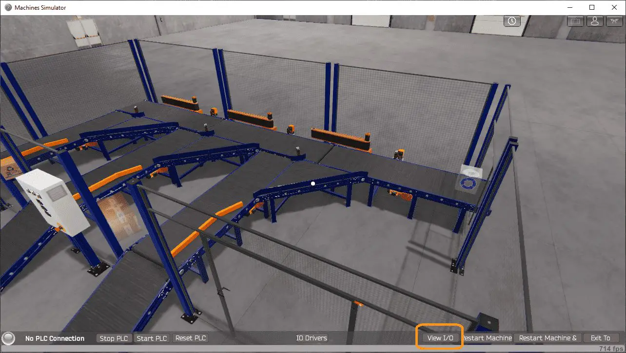
Start the box selection in start mode.
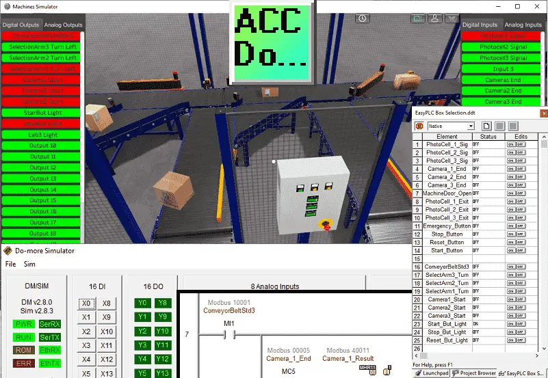
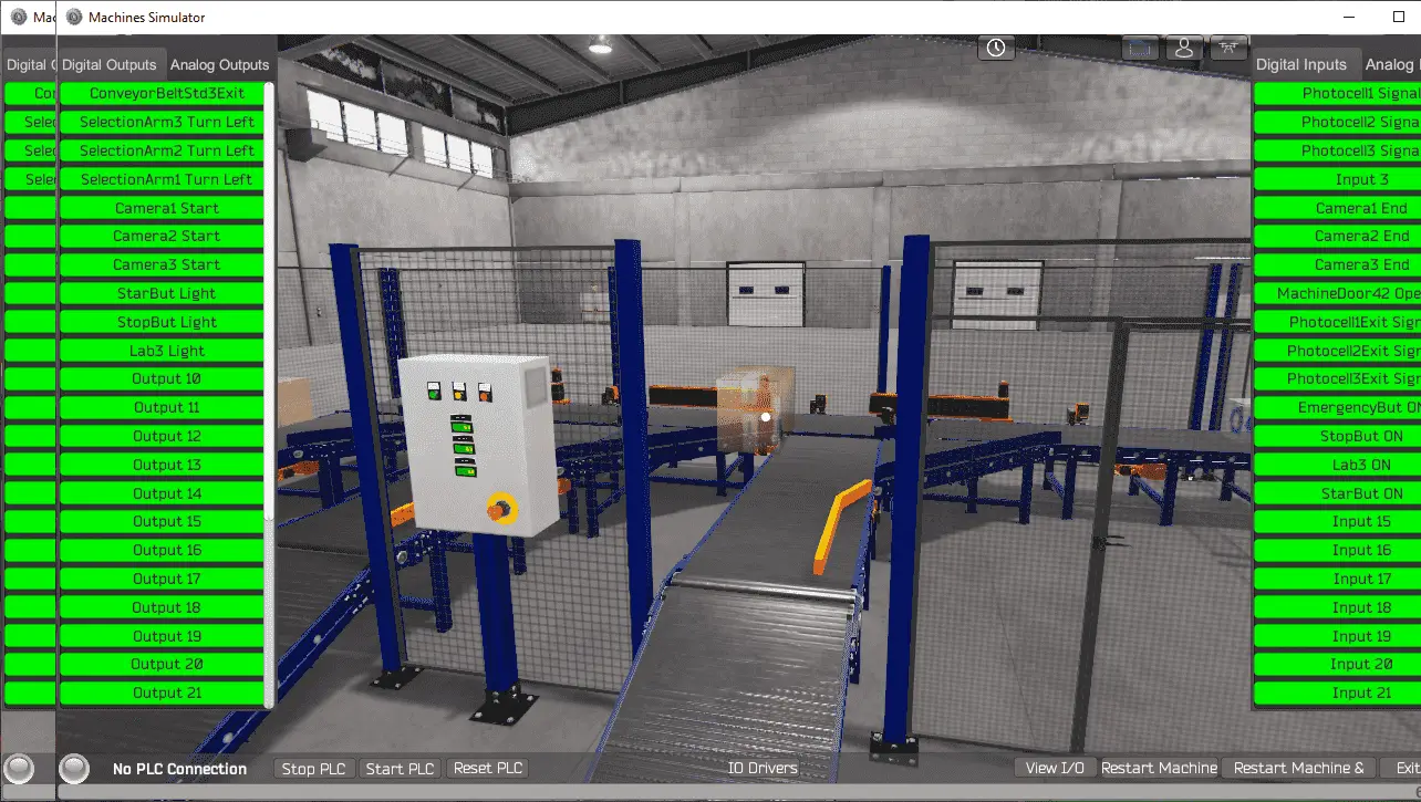
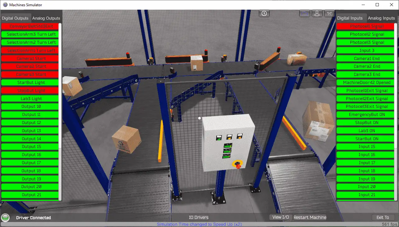
Select the View IO to display the inputs and outputs required for this machine.
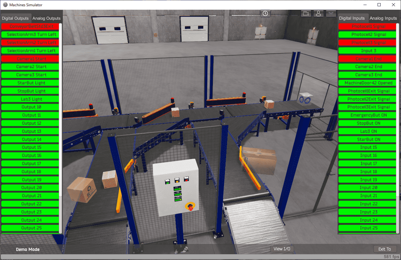
 The EasyPLC box selection machine simulator will require ten digital outputs and 15 digital inputs. It will also need three analogs in and out. The analog outputs are for the exit ramp counts. Analog inputs are for each camera on the exit ramps to read the box barcode.
Clicking on the digital outputs will activate it. Spend time understanding the IO (inputs and outputs) functions fully.
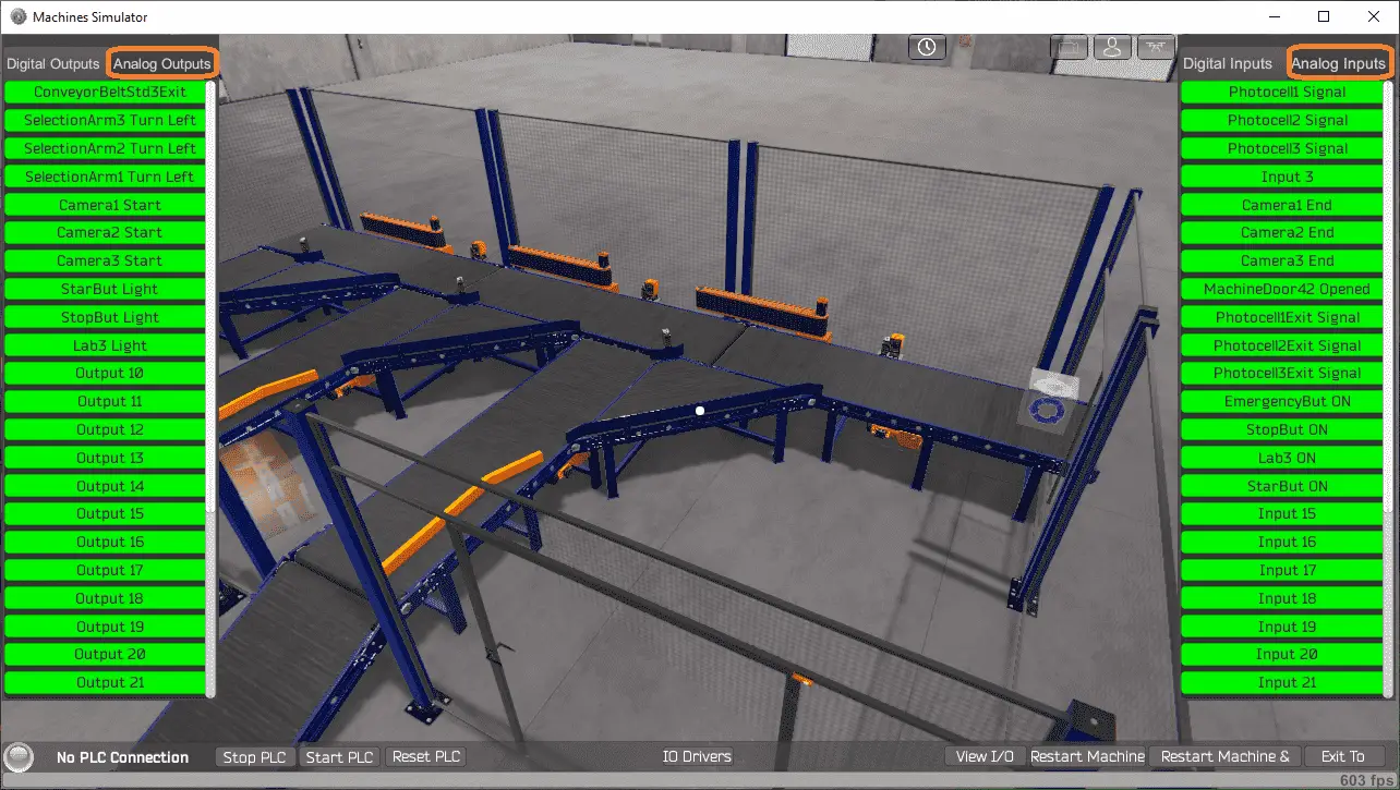
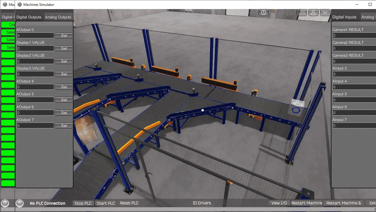 You can move around in the 3D environment and see the IO and items from different angles. Clicking on the analog will call up the analog IO for you to interact.
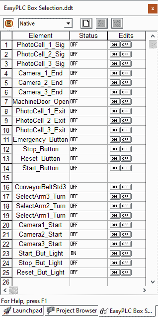
 The following table will define the inputs and outputs (IO) and Modbus addresses in the Do-More Designer Simulator we will use for this program.
| Digital Type | Description | Productivity Modbus Address | Machine Simulator Modbus Address |
| PLC Output – MS Input | Conveyor Belt Start 3 | 10001 – MI1 | 0 |
| PLC Output – MS Input | Select Arm 3 Turn | 10002 – MI2 | 1 |
| PLC Output – MS Input | Select Arm 2 Turn | 10003 – MI3 | 2 |
| PLC Output – MS Input | Select Arm1 Turn | 10004 – MI4 | 3 |
| PLC Output – MS Input | Camera 1 Start | 10005 – MI5 | 4 |
| PLC Output – MS Input | Camera 2 Start | 10006 – MI6 | 5 |
| PLC Output – MS Input | Camera 3 Start | 10007 – MI7 | 6 |
| PLC Output – MS Input | Start Button Light | 10008 – MI8 | 7 |
| PLC Output – MS Input | Stop Button Light | 10009 – MI9 | 8 |
| PLC Output – MS Input | Reset Button Light | 10010 – MI10 | 9 |
| Analog PLC Output – MS Input | Exit 1 Conveyor Count | 40002 – MHR2 | 1 |
| Analog PLC Output – MS Input | Exit 2 Conveyor Count | 40003 – MHR3 | 2 |
| Analog PLC Output – MS Input | Exit 3 Conveyor Count | 40004 – MHR4 | 3 |
| PLC Input – MS Output | PhotoCell 1 Signal | 1 – MC1 | 0 |
| PLC Input – MS Output | PhotoCell 2 Signal | 2 – MC2 | 1 |
| PLC Input – MS Output | PhotoCell 3 Signal | 3 – MC3 | 2 |
| PLC Input – MS Output | Camera 1 End | 5 – MC5 | 4 |
| PLC Input – MS Output | Camera 2 End | 6 – MC6 | 5 |
| PLC Input – MS Output | Camera 3 End | 7 – MC7 | 6 |
| PLC Input – MS Output | Machine Door Open | 8 – MC8 | 7 |
| PLC Input – MS Output | PhotoCell 1 Exit | 9 – MC9 | 8 |
| PLC Input – MS Output | PhotoCell 2 Exit | 10 – MC10 | 9 |
| PLC Input – MS Output | PhotoCell 3 Exit | 11 – MC11 | 10 |
| PLC Input – MS Output | Emergency Button | 12 – MC12 | 11 |
| PLC Input – MS Output | Stop Button | 13 – MC13 | 12 |
| PLC Input – MS Output | Reset Button | 14 – MC14 | 13 |
| PLC Input – MS Output | Start Button | 15 – MC15 | 14 |
| Analog PLC Input – MS Output | Camera 1 Result | 40011 – MHR11 | 10 |
| Analog PLC Input – MS Output | Camera 2 Result | 40012 – MHR12 | 11 |
| Analog PLC Input – MS Output | Camera 3 Result | 40013 – MHR13 | 12 |
Note: The machine simulator will be offset by one on the Modbus Addresses.
Develop a logical sequence of operation (Step 3 – Box Selection)
A flow chart or sequence table is used to understand the process that needs to be controlled thoroughly. It must also answer questions like the following:
What happens when electrical power and/or pneumatic air is lost? What happens when the input/output devices fail? Do we need redundancy?
This step is where you can save yourself a lot of work by understanding everything about the operation. It will help prevent you from continuously re-writing the PLC program logic. Knowing all of these answers upfront is vital in developing the PLC program.
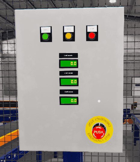
The control panel of the EasyPLC Box Selection program will show the operator information. If the gate is opened, the red LED will flash. In the stop mode, the green LED will be on, indicating this is how to start the line. When the line runs, the red LED will be on, telling how to stop the machine. An emergency stop will turn all of the LEDs off. The exit conveyor counts will show how many boxes have been diverted to it. When the machine is stopped, and the box counts are greater than 0, then the reset LED will be on. Pressing the reset will zero the counts and turn off the LED.
Our EasyPLC Box Selection program can be seen as three independent exit conveyor operations. A box will pass by, and the camera and photocell will then read the barcode. If the barcode is for this conveyor, the arm will be activated, diverting the box. When the exit photocell is on, this will reset the arm.
A PLC programmer must know how everything about the sequence and operation of the machine before programming.
Ask questions or view existing documentation to ensure you know the logical steps to the machine’s operation.
Develop the Do-More PLC program (Step 4 – Box Selection)
Writing the ladder logic code for the PLC example will be the next step in our program development. Detailed information on the Do-More PLC and simulator can be found here.
Start the Do-More Designer PLC software and select Start a new Project. We will be using the Do-More Simulator with our EasyPLC Machine Simulator.
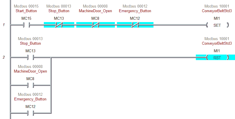
The first rung of code will set the conveyor belts running for our box selection program. This is done with the set and reset instructions. The conveyor reset will happen when a stop, machine door, or emergency button is selected.
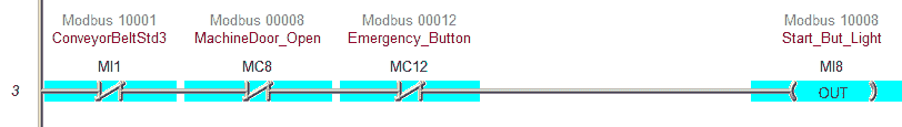
The start light will be on when the machine is ready to be started.
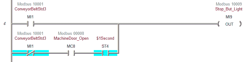
The stoplight will be on when the machine is running. A flashing stoplight will indicate that the machine is stopped and the door is opened.
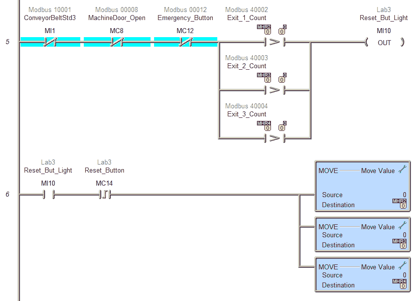
The reset button will be lit when the machine is stopped, and any exit conveyors have a count greater than 0. The reset button will reset the counts for each exit conveyor for the box selection program.
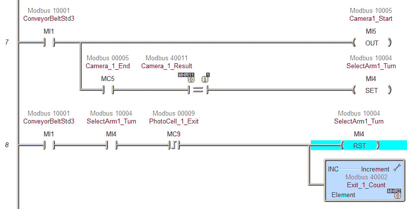
Exit 1 Conveyor
If the conveyors are running, the camera is turned on. When the camera end is seen, the result is compared to the exit number. If this matches, then set the selection arm for the exit. Once the photocell on the exit is seen, reset the selection arm and increment the exit count by 1 for our box selection.
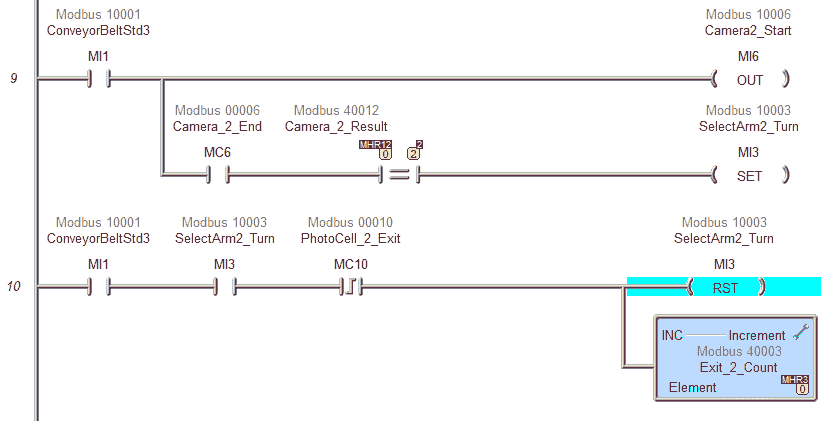
Exit 2 Conveyor
If the conveyors are running, the camera is turned on. When the camera end is seen, the result is compared to the exit number. If this matches, then set the selection arm for the exit. Once the photocell on the exit is seen, then reset the selection arm and increment the exit count by 1 for our box selection.
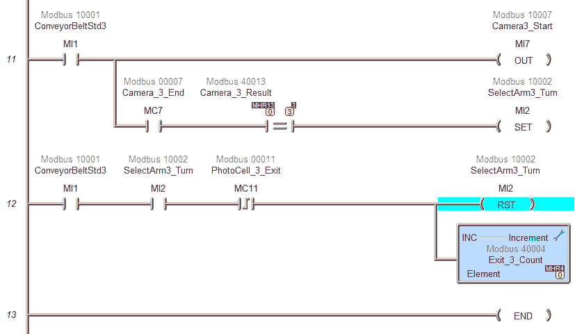
Exit 3 Conveyor
If the conveyors are running, the camera is turned on. When the camera end is seen, the result is compared to the exit number. If this matches, then set the selection arm for the exit. Once the photocell on the exit is seen, then reset the selection arm and increment the exit count by 1 for our box selection.
This is our complete program. See below to download the program and machine simulator scene.
Call up the system configuration in the Do-More Designer Software. This is done by selecting System Configuration from the main menu | PLC | System Configuration.
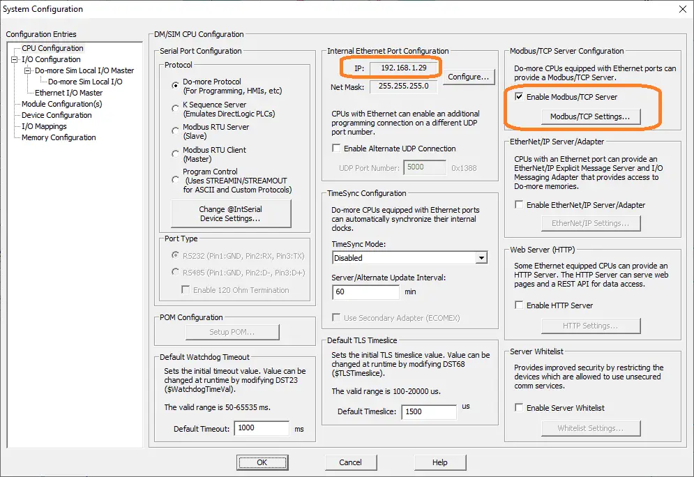
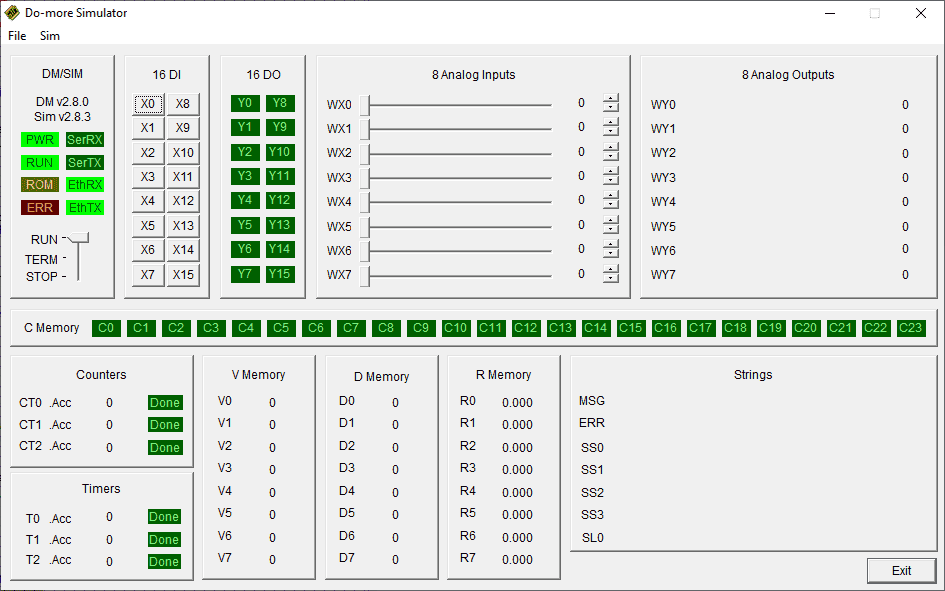
This will show us the current IP address of the Do-More Designer Simulator and will ensure that the Modbus TCP server is enabled.
Transfer the program to the Do-More Simulator.
You can now use the Data View in the Do-More to monitor the inputs and outputs of the simulator.
Test the program: (Step 5 – Box Selection)
We will use Modbus TCP on our Do-More PLC simulator to communicate with the machine simulator. The Do-More PLC simulator is part of the free Do-More Designer PLC programming software.
Call up the box selection machine in start mode.
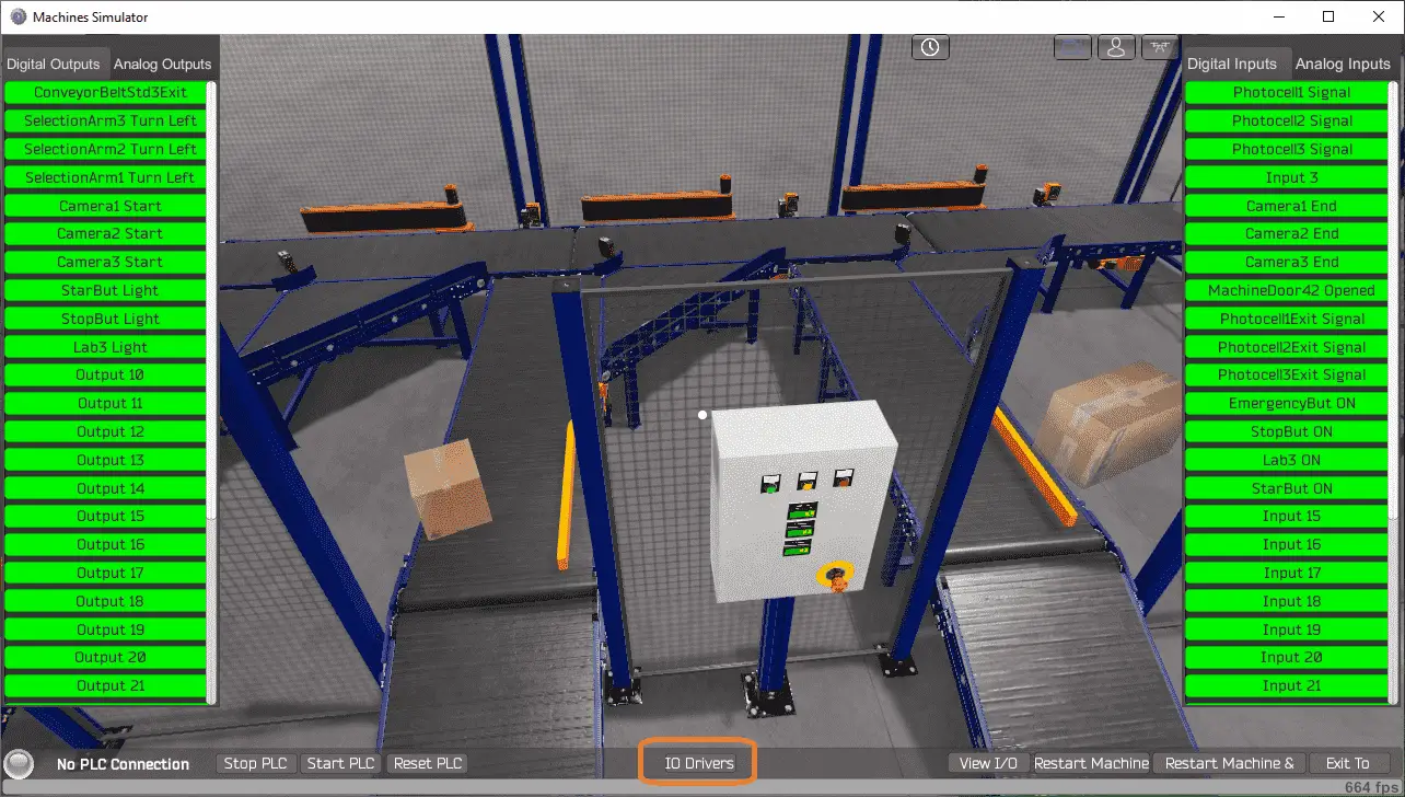 The status of the machine simulator will be at the bottom of the screen. Currently, we have no PLC connected.
Select IO on the bottom middle of the screen.
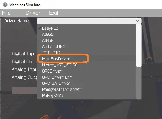
Under the driver pull-down menu, select “ModBusDriver.”
This driver will communicate Modbus TCP (Ethernet) and Modbus RTU (Serial).
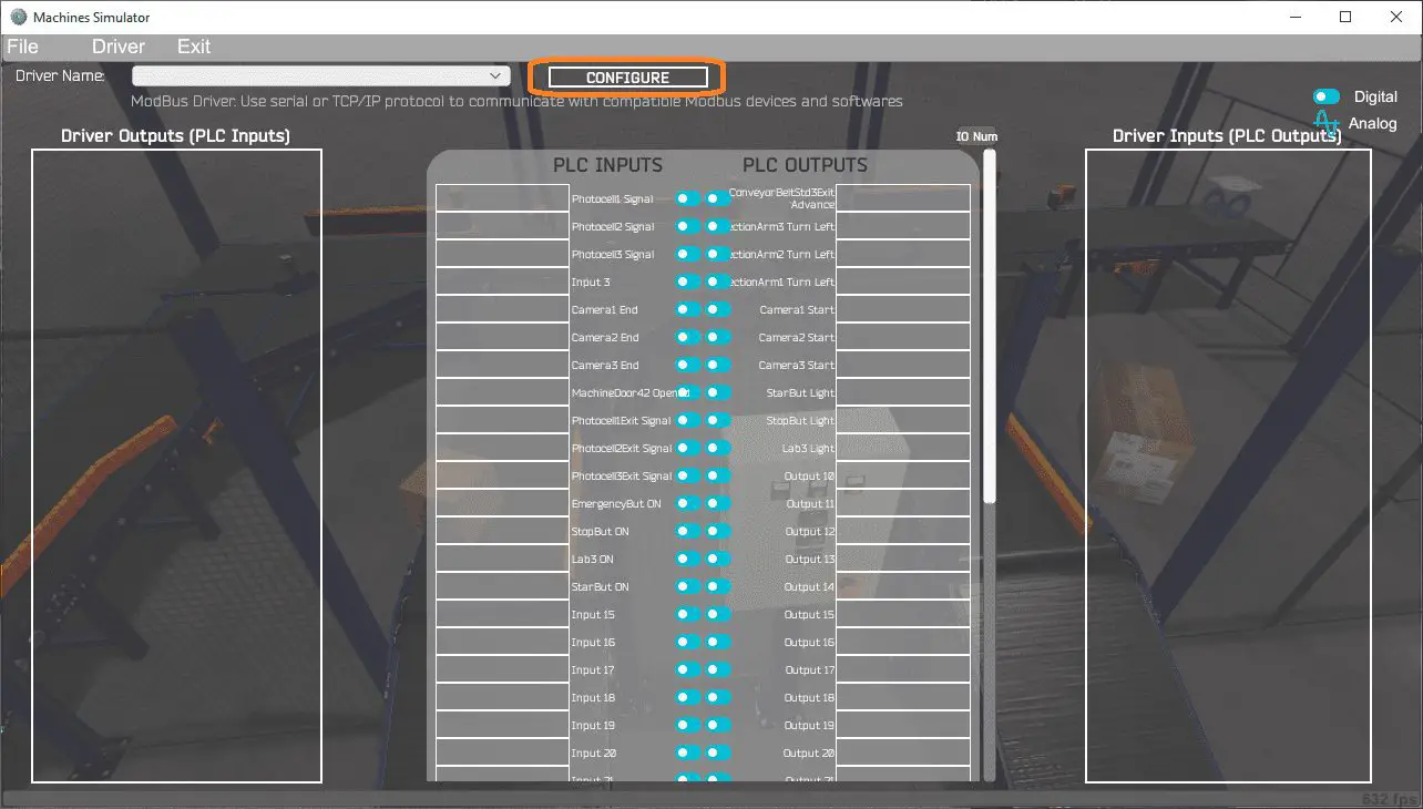 Select the configure button.
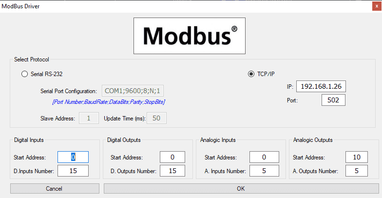
We can now enter the information for our Modbus driver. Select TCP/IP. This means the Ethernet port on the computer will communicate to the PLC. The IP address will be set for the same as our Do-More PLC Simulator shown above.
The digital inputs from MS to the Do-More PLC will start at MI1. This will start at address 0 due to the offset of 1. Digital outputs from MS to the Do-More PLC will start at MC1. This will start at address 0 due to the offset of 1. Analog inputs and outputs will start at MHR1 in the Do-More PLC. Since the analog outputs share the exact memory location as the inputs, there is an offset. See the table above.
Select the OK button.
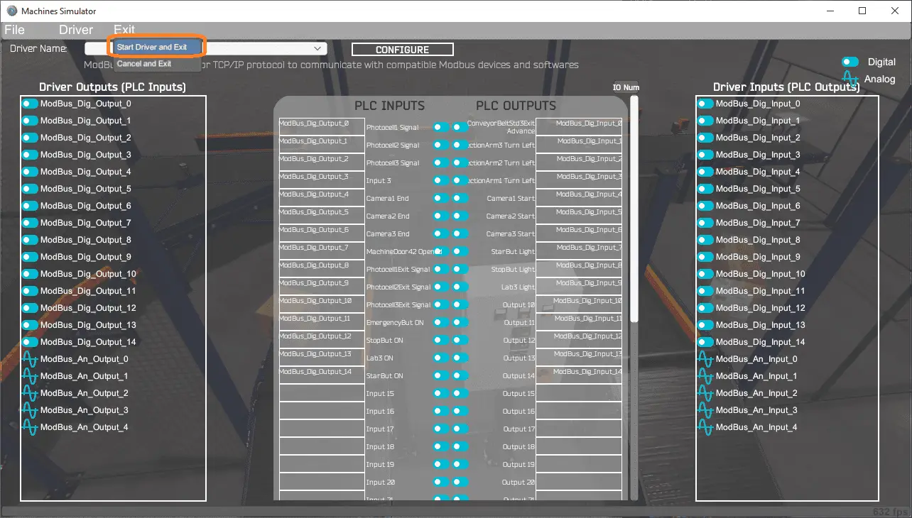 You will now see the inputs and outputs specified for the Modbus driver. We can now manually assign the driver outputs to the PLC inputs and the driver inputs to the PLC outputs.
Select Automatic Assignment from the driver option in the main menu.
This will automatically assign the PLC IO to the Machine Simulator IO.
Select Start Driver and exit from the main menu.
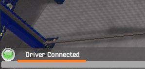
You will see on the bottom left side of the window that the driver is operating. Select view IO to know the input and output status of the machine simulator.
Ensure that the PLC is in run mode. We can now operate the machine simulator through the control panel.
 Using the Data View window of the Click programming software, we can also watch the inputs and output operations.
Using Machine Simulator (MS) to test the program will ensure that our program works.
The machine simulator has a time frame that you can speed up or slow down the process to help you troubleshoot. Watch the video below to see this operation.
Download the Do-More PLC sample program and machine simulator MS for the box selection machine.
Watch the video below to see the five steps of program development applied to the transfer line. The machine simulator is one of the best applications to help you learn PLC programming.
EasyPLC Software Suite is a complete PLC, HMI, and Machine Simulator Software package. This PLC learning package includes the following:
Easy PLC – PLC Simulation will allow programming in Ladder, Grafcet, Logic Blocks, or Script.
HMI System – Easily create a visual human-machine interface (HMI)
Machine Simulator – A virtual 3D world with real-time graphics and physical properties. PLC programs can be tested using the EasyPLC or through other interfaces. (Modbus RTU, TCP, etc.)
Machine Simulator Lite – Designed to run on Android Devices.
Machine Simulator VR – Virtual Reality comes to life so you can test, train, or practice your PLC programming.
Purchase your copy of this learning package for less than USD 75 for a single computer install or less than USD 100 to allow different computers.
Receive 10% off the price by typing in ACC in the comment section when you order. http://www.nirtec.com/index.php/purchase-price/
Learn PLC programming the easy way. Invest in yourself today.
Watch on YouTube: Do-More PLC – EasyPLC Box Selection Program
If you have any questions or need further information, please get in touch with me.
Thank you,
Garry
If you’re like most of my readers, you’re committed to learning about technology. Numbering systems used in PLCs are not difficult to learn and understand. We will walk through the numbering systems used in PLCs. This includes Bits, Decimals, Hexadecimal, ASCII, and Floating Points.
To get this free article, subscribe to my free email newsletter.
Use the information to inform other people how numbering systems work. Sign up now.

The ‘Robust Data Logging for Free’ eBook is also available as a free download. The link is included when you subscribe to ACC Automation.