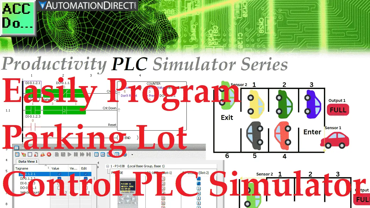
Programming a simple parking lot control is quickly done with the Productivity PLC Simulator. This comprehensive software suite is developed to simulate and control the PLC’s creation, management, and operation without the hardware. It accurately represents the complete PLC hardware from inputs, outputs, and logic control. The intuitive software enables you to understand, develop, debug, and monitor the entire system in a safe environment. This allows you to start testing before your actual implementation.
This tutorial will guide beginners or experienced PLC programmers on how to use this robust PLC programming simulator. We will be programming a simple parking lot control counter with a full sign output. Let’s get started.
Install the Productivity software.
Productivity Suite is user-friendly programming software designed to allow quick and easy programming of ladder logic programs for the Productivity®1000, Productivity®2000, and Productivity3000® CPUs. The software includes a simulator that will mimic any of the PLC controllers. This controller family will impress with its tag-based addressing and extensive instruction set. The online help file provides information that will help you quickly get acquainted with the software.
Download your free, fully functional Productivity Suite Software here.
PC Requirements Productivity Suite
Operating Systems
Windows 11
Windows 10
Hardware
Processor:2.6 GHz (multi-core recommended)
Memory:4GB (8GB recommended)
Storage:2GB storage space
Video: No requirement specified
Other: USB or Ethernet connection required to transfer the project to the CPU
Here is a link to a post showing you the installation of the software.
Simple Parking Lot Control
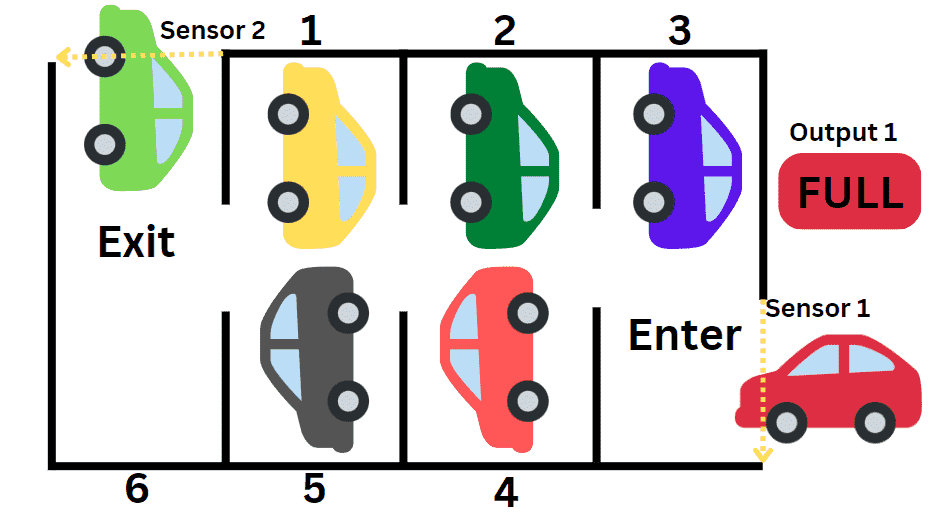
We will be using the Productivity Suite PLC Simulator to control the following parking lot with six parking locations.
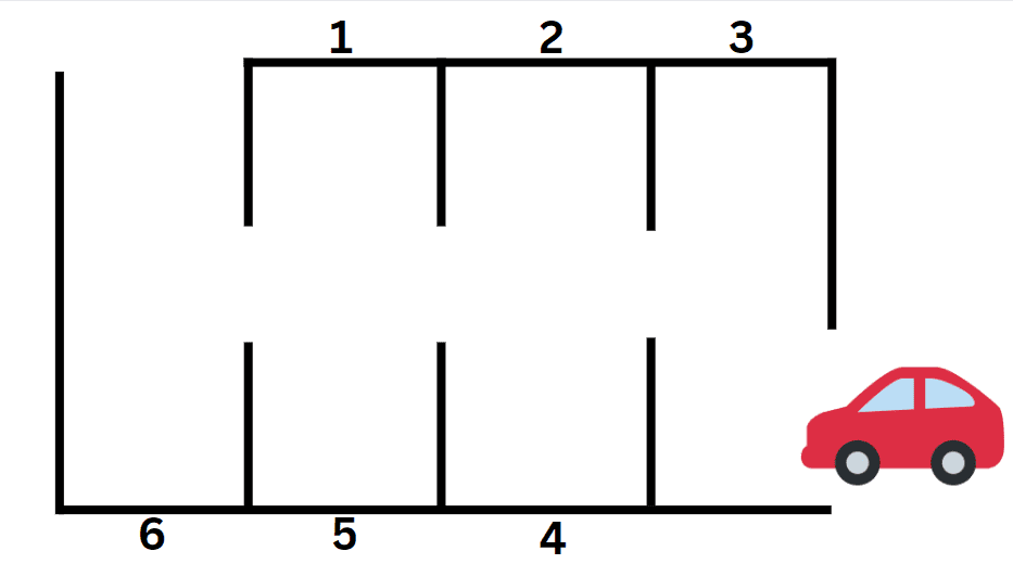
Cars will enter the parking lot and be counted. So as this red car enters, the vehicle count will increment by a value of 1. When the car leaves the parking lot, the vehicle count will decrease by 1.
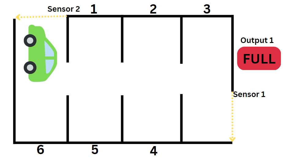
After the vehicle count is 6, the output will be turned on, indicating that the parking lot is full.
Define the PLC inputs and outputs
Start the Productivity Suite PLC programming software.
Select New Project under the File on the main menu.
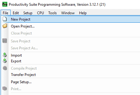
You can also select the new project icon on the main menu.
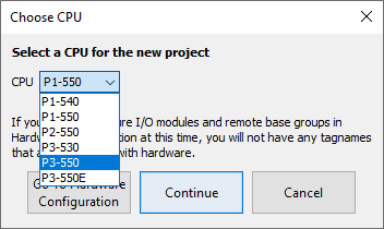
The Choose CPU window will now be displayed. Clicking the arrow beside the CPU will list all of the available CPUs. Select the P3-550E productivity 3000 (P3000) PLC.
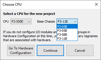
The base chassis will now be shown. Select the P3-03B base. This will contain three slots to place input and output cards.
Select the go-to hardware configuration button.
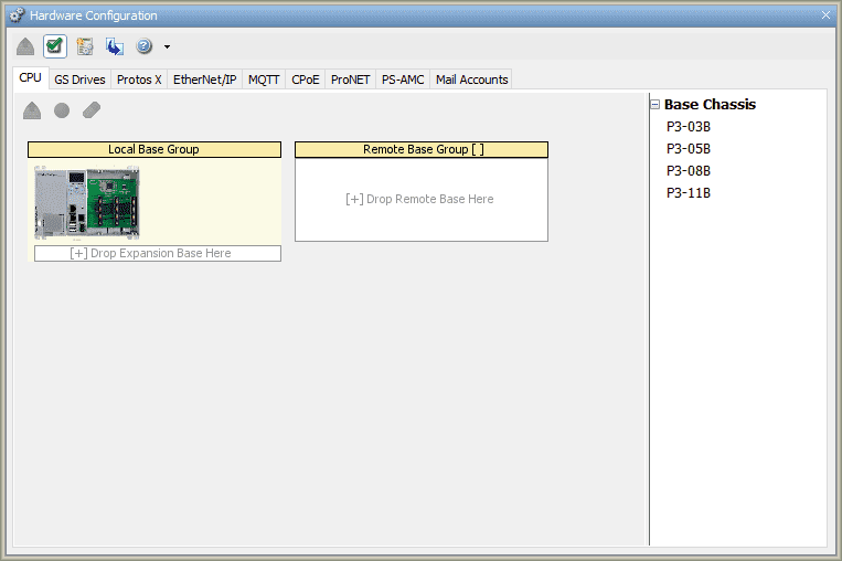
This will now display the hardware configuration window. This shows the local base group and all remote stations. In our application, we will only be using the base group.
Double-click on the local base PLC.
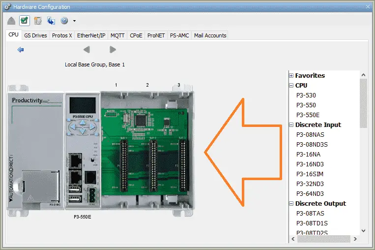
We can now add our inputs and output to the PLC rack.
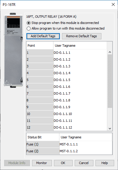
Add a P3-16TR by locating it under the discrete outputs in the hardware configuration. Click and drag this to the first slot on the CPU rack. We will use the default tags for this card.
Select OK.
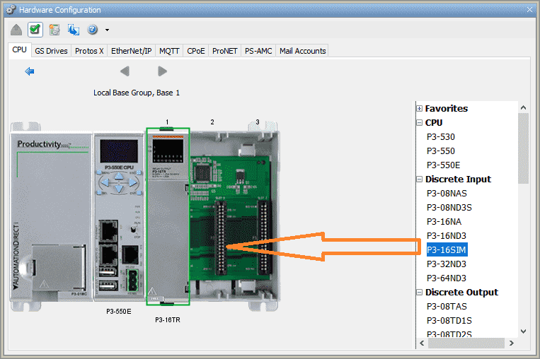
Select the P3-16SIM discrete input card. Click and drag this into slot 2 of the CPU rack.
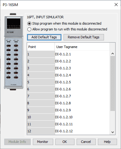
We will once again use the default tags for this card. Select OK.
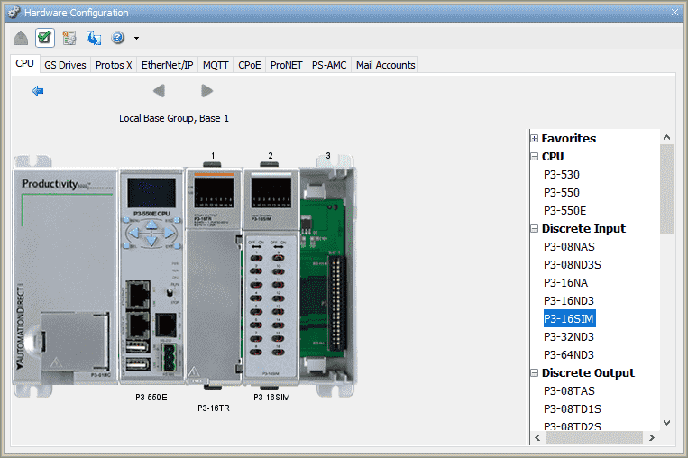
Our hardware configuration is now set. Click on the X in the upper right-hand side of the window to close.
 The parking lot control example will use the first input in slot 2 to add cars and the second input to subtract cars. The third input will reset the total vehicle count.
Our parking lot full output will be the first output on slot 1.
Develop the PLC Program
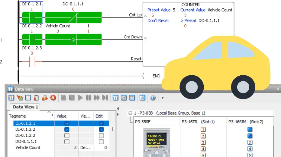
Our parking lot control example is a counter. The entrance input is for incrementing the counter, and the exit is for decrementing the counter. When the counter reaches the maximum value of 6, the output will indicate that the parking lot is full.
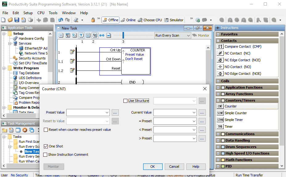
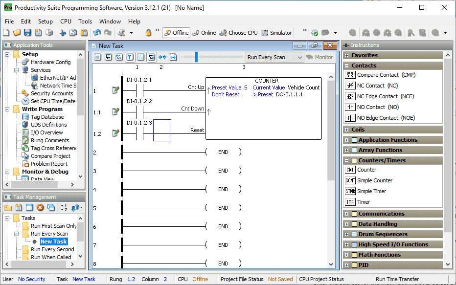
With the cursor on the rung one, double-click on the counter (CNT) instruction. You can also click and drag the instruction onto the ladder rung area.
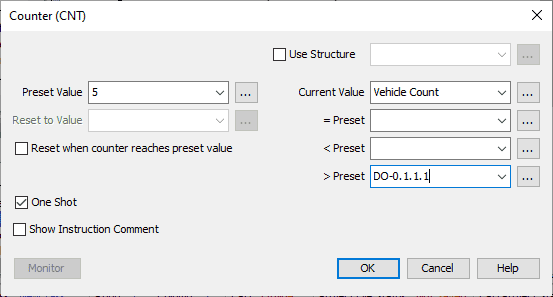
Our output will be placed on the greater than the preset value. This is address DO-0.1.1.1. Since we are using the greater than, our preset value will be set to a constant value of 5. The inputs will be selected for One Shot. This means that the input will count when a transition from off to on occurs.
We will use a tag called Vehicle Count for the current value of this counter. Select OK.
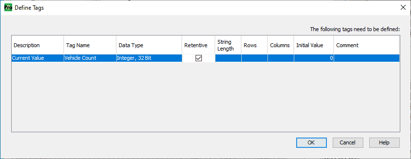
The vehicle count tag can now be defined. We will select this as retentive so that this value is remembered when power is removed and then restored to the PLC. Select OK.
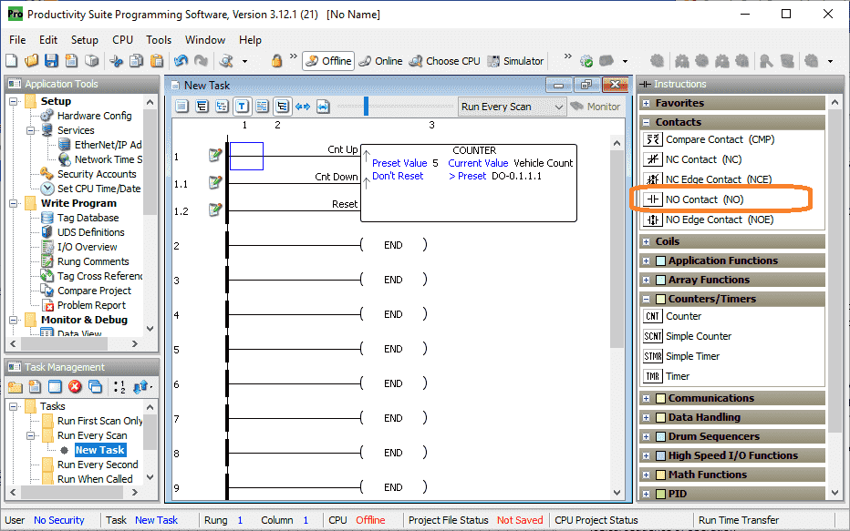
Our counter has now been put on rung 1. There are three inputs to our counter. Position the cursor on the first input to the counter. Double-click on the NO contact or click and drag this to the position for the counter input.
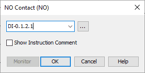
Enter the address for the first input in slot 2. Select OK.
Do the same for the second and third inputs to the counter using the following two inputs.
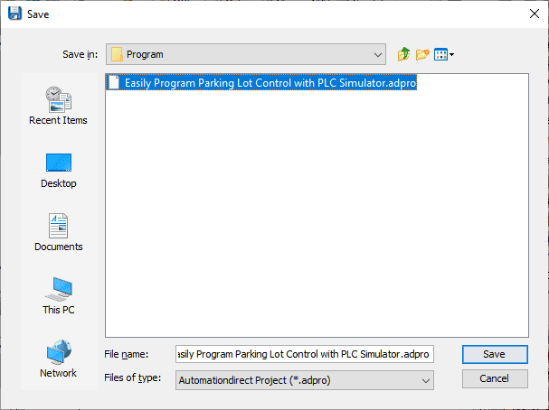
Select the save. Give the program a name and select save.
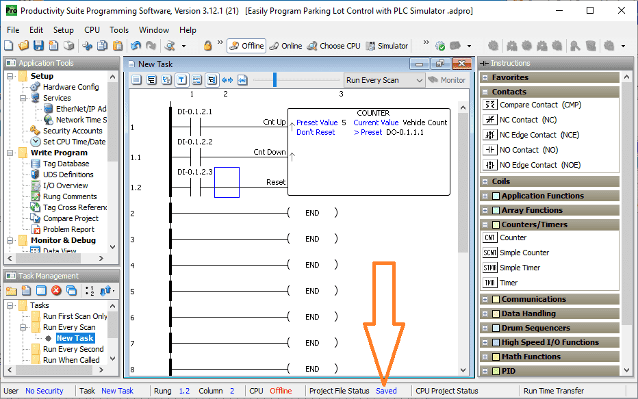
Our program is now complete.
Test / Modify the PLC Program
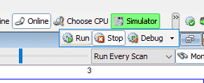
Select simulator from the main menu | CPU | Simulator.
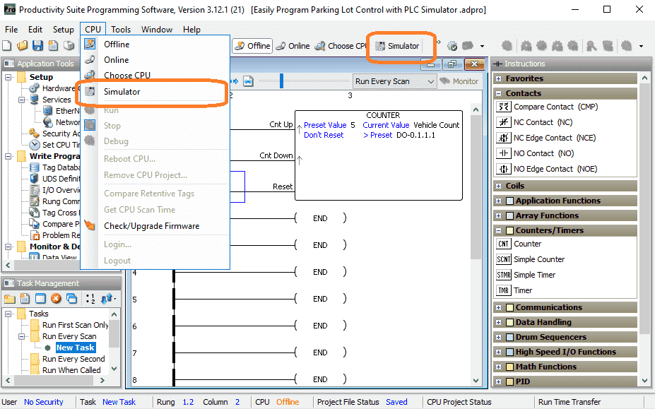
You can also use the icon on the main menu.
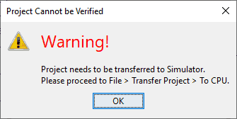
The following warning window will be displayed. We will need to transfer the project to the CPU. The simulator will be treated as a separate identity, just like a physical PLC.
Select OK.
Transfer the program to the PLC by selecting the icon on the main menu. You can also do this by selecting the main menu | File | Transfer Project | To CPU…
Shift + F9 will also transfer the program to the CPU.

Our program will now be transferred. You may be notified that retentive tags cannot be retrieved from the CPU. Keep the current retentive tag values and select Yes.
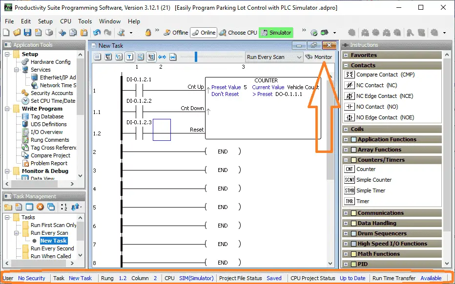
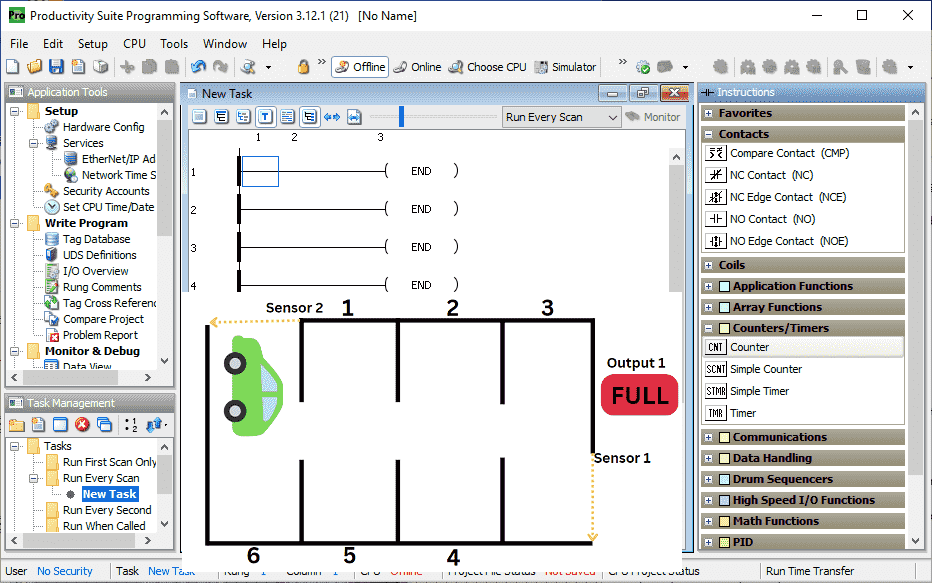
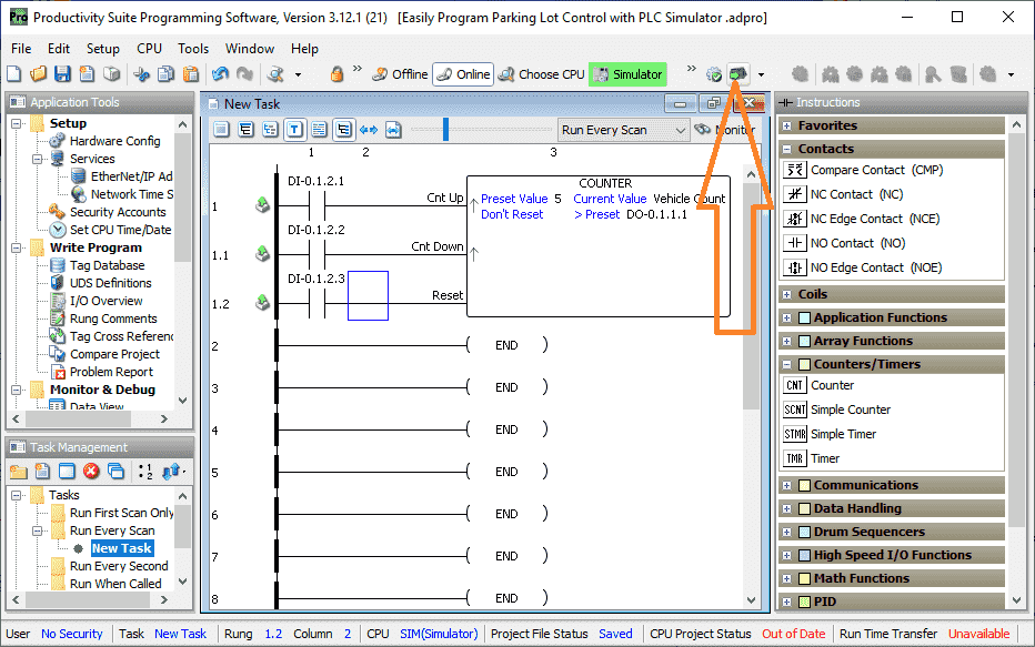
The status of the project and communication is available at the bottom of the productivity suite programming software window. Select the monitor icon on the new task window.
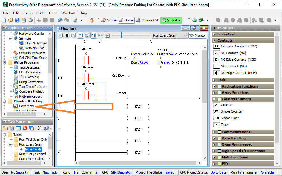
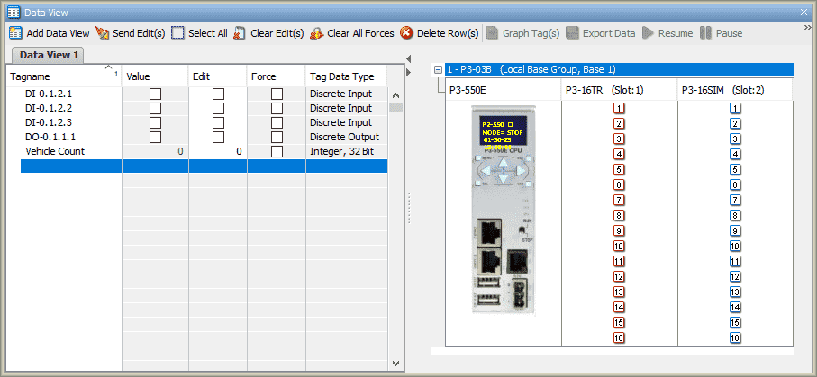
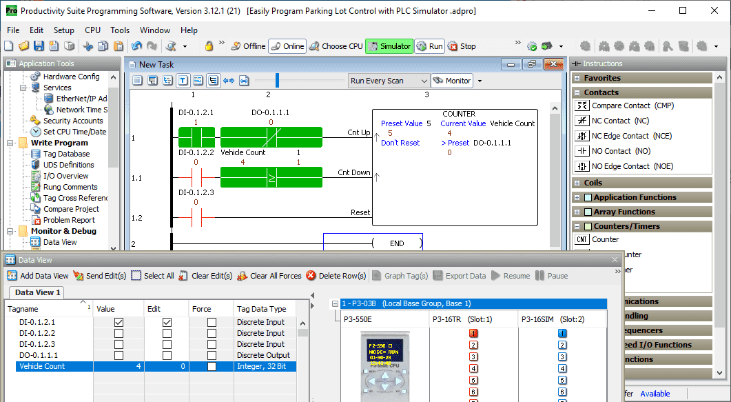
Our counter values, along with the inputs, can now be seen. Select the Data View under the Monitor & Debug heading in the Application Tools. You can also use the shortcut of Ctrl + Shift + F3 or the main menu | Tools | Data View.
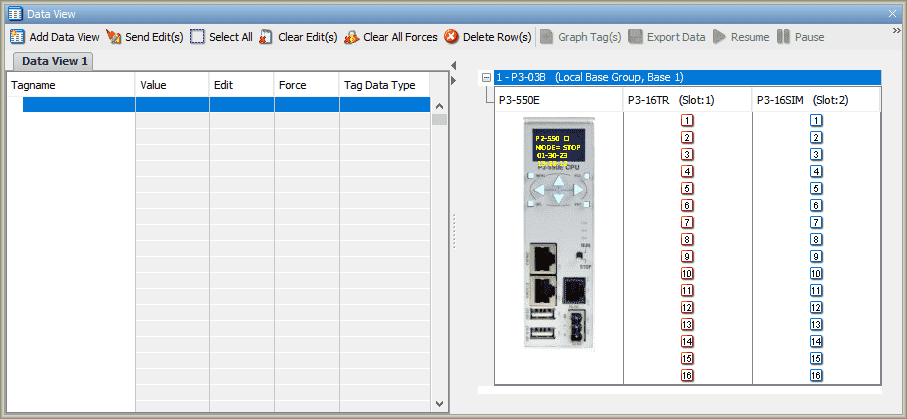
The data view window will default to showing the tag and IO view. The IO view on the right will show the picture of the CPU and the inputs and output status.
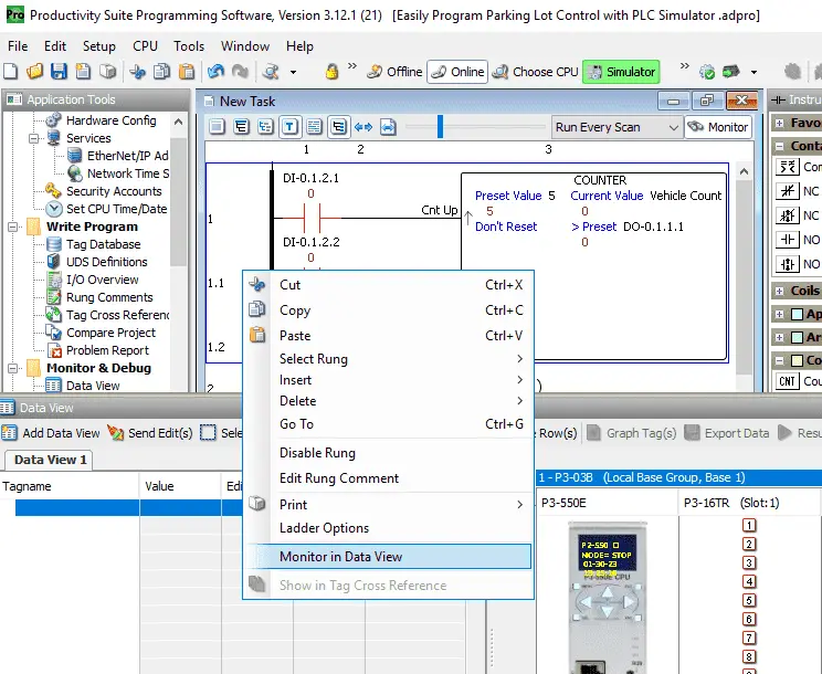
Right-click on the rung and select monitor in data view.
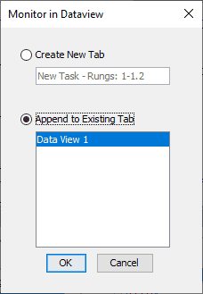
Select append to the existing tab. Since we have only one, Data View 1 will be selected. Select OK.
The selected rung tags will now appear on the tag view list.
Select Run on the main menu to start the PLC simulator scanning the logic.
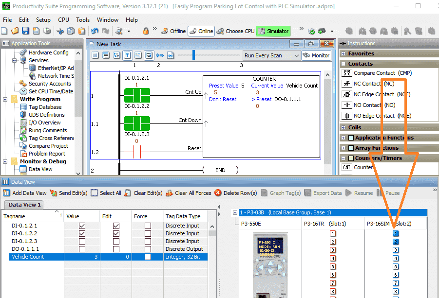
You can see the ladder logic function and the tag views update as you click on the inputs in the IO view window. Test your program.
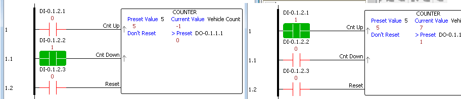
You can see that we can go above six on our counter and below 0.
Let’s modify the logic so the count cannot go higher than six or lower than 0.
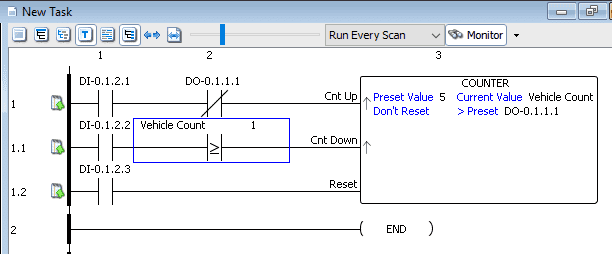
We have added our output contact for the counter-up input. If the output is on, the counter will not increment.
A comparison is added to the countdown input. The decrement input will work if the vehicle count is greater than or equal to 1. If the count is below 1, the input to decrement is disabled. Save the program.
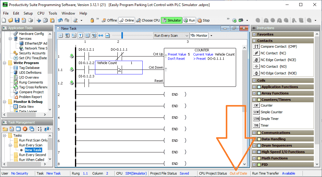
You will see that the CPU Project Status is out of date. This means that we must transfer the project again to the CPU. This time we will do this online. The program will still be executing and adding the modifications. The PLC will not be put into the program (stop) mode. Select the program transfer.
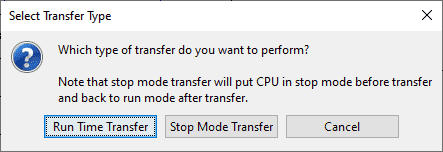
Select run time transfer.
Our modified program is now running.
Test again to see that the program is working correctly.
See the video below for the programming of this simple parking lot control PLC simulator example.
Download this PLC Sample Program here.
Free learning and training series for PLCs.
Productivity Series
P1000
P2000
BRX Do-More
Click / Click PLUS (Koyo)
Omron CP1H Series
Horner XL4 Series
EasyPLC Software Suite – 3D training package
Purchase your copy of this learning package for less than USD 75 for a single computer install or less than USD 100 to allow different computers.
Receive 10% off the investment by typing in ACC in the comment section when you order. http://www.nirtec.com/index.php/purchase-price/
Learn PLC programming the easy way. Invest in yourself today.
C-More EA9 Series of HMI
(Webserver, FTP, Data Logging, Free Remote Apps, etc.)
Node-Red is a free IoT software hub that can communicate MQTT and many standard industrial protocols. This series will help you communicate to the PLC, create an HMI on any electronic device, log data to a database, and view the information on a spreadsheet for analysis.
Node-RED IoT enabling software
Watch on YouTube: Easily Program Parking Lot Control with PLC Simulator
If you have any questions or need further information, don’t hesitate to contact me.
Thank you,
Garry
If you’re like most of my readers, you’re committed to learning about technology. Numbering systems used in PLCs are not challenging to learn and understand. We will walk through the numbering systems used in PLCs. This includes Bits, decimals, Hexadecimal, ASCII, and Floating points.
To get this free article, subscribe to my free email newsletter.
Use the information to inform other people how numbering systems work. Sign up now.

The ‘Robust Data Logging for Free’ eBook is also available for free download. The link is included when you subscribe to ACC Automation.