Programming a C-more CM5 HMI (Human-Machine Interface) or any other unit can initially seem daunting, but it can be a rewarding experience with the proper guidance. This post will walk you through the steps to program a C-more HMI unit, specifically the CM5 HMI model. Whether you’re a beginner or have some experience with HMI programming, this guide will help you get started with programming your C-more HMI unit.
We will familiarize ourselves with the C-More CM5 programming software and establish Communications from the PC to the CM5. We will then develop our control for our PLC ladder logic circuit.
The PLC logic for our circuit can be found in our post: How to Make a Start / Stop / Jog Circuit in a PLC. The YouTube video can be seen here.
Our C-More CM5 HMI Panel will communicate with the PLC simulator via Ethernet. Let’s get started.
Previously in this C-More CM5 HMI Panel series, we have done the following:
Latest C-More CM5 HMI Game Changer Post
– C-More CM5 Unboxing and Power Video
Installing C-more CM5 HMI Software Step by Step – Video
C-More CM5 HMI Series Panel System Setup Screens – Video
C-More CM5 HMI Communication Firmware Update – Video
See the list of references for the CM5 HMI, including the frequently asked questions (FAQ) at the end of this post.
Step 1: Familiarize Yourself with the C-more CM5 Program Software
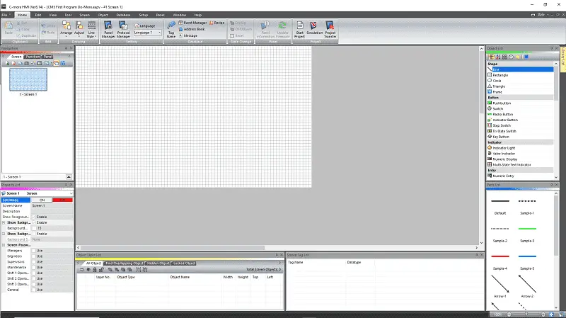
The first step in programming a C-more CM5 HMI unit is to become familiar with the C-more programming software. This software allows you to create a graphical interface and program the HMI unit’s functionality. Open the C-More CM5 programming software.
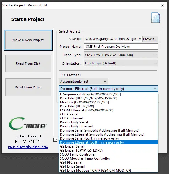
The “Start a Project” window will be shown. Enter the project name. Under the Panel Type, enter our panel CM5-T7W. The panel will be oriented in the default landscape mode. This option can be set if the panel is physically mounted vertically. We will connect to the Do-More Designer PLC Simulator. Set the PLC Protocol for AutomationDirect.
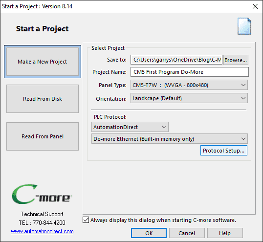
Select the Do-more Ethernet (Built-in memory only) for the driver. We will export and input the tag information from the PLC to the HMI. We will only be using the built-in memory in the simulator. Select the “Protocol Setup…” button.
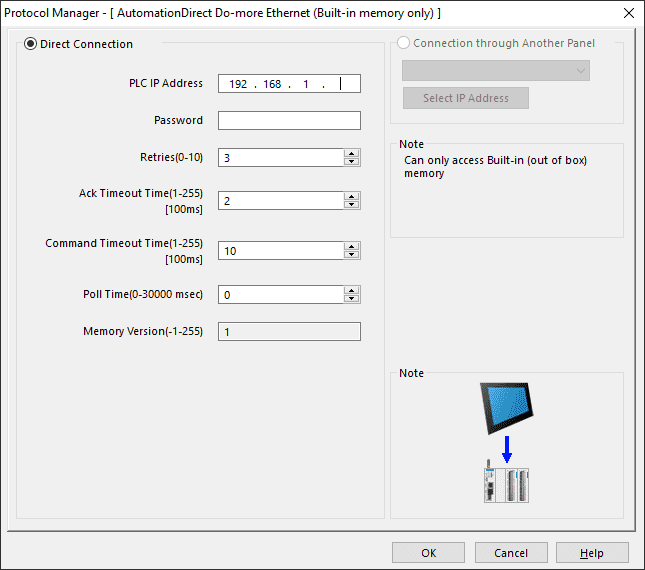
Enter the PLC IP Address we will use in the Protocol Manager window. This will be the IP address of the computer running the PLC Simulator. Select OK.
As we work with the C-More CM5 programming software, you will learn how to use it. Take some time to explore the various features and tools available in the software, and refer to the user manual for detailed instructions. We did this last time when we installed the software.
Step 2: Design the HMI Interface
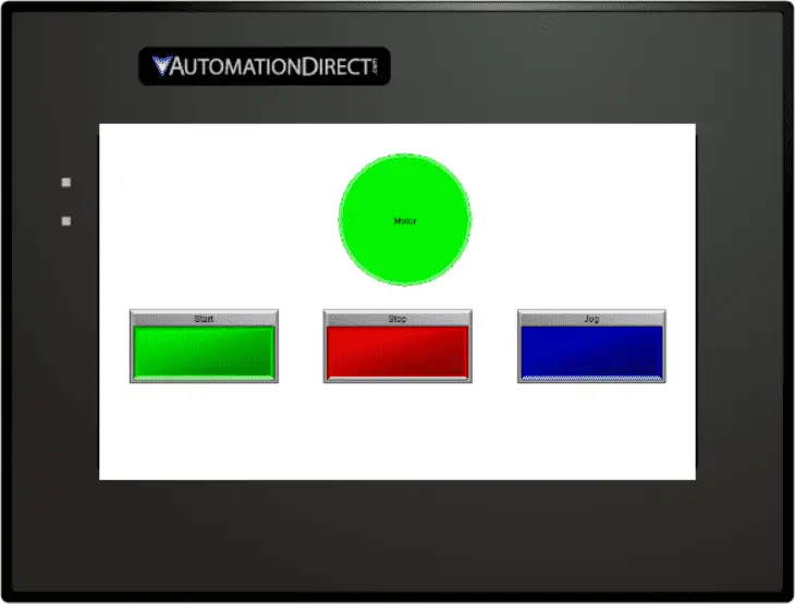
Once you are comfortable with the C-more CM5 programming software, it’s time to design the HMI interface. This can be one of the hardest things to do in HMI programming. The design must be intuitive enough so the operators can easily maneuver around each of the screens you program. In our case, we will use just one HMI screen.
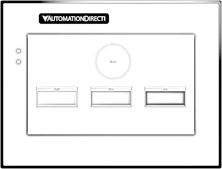
This will show the start, stop, and jog buttons. It will also show the motor output condition. Once we have the design of the HMI, let’s look at the PLC logic.
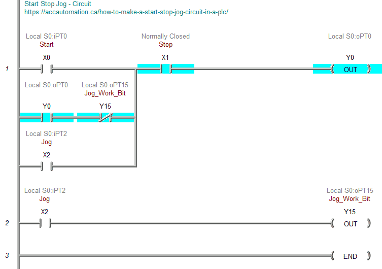
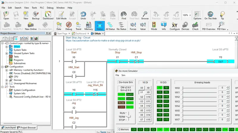
Here is our existing PLC program logic for the start, stop, and jog. Since we want to control this from the HMI, we must add additional HMI input elements. Remember that the communication in the PLC will happen once per scan. Communication with the HMI is slower than the actual physical input and outputs on the PLC within the scan. We can easily read the status of all memory areas in the PLC with the HMI; however, writing information must be unique in bits and words.
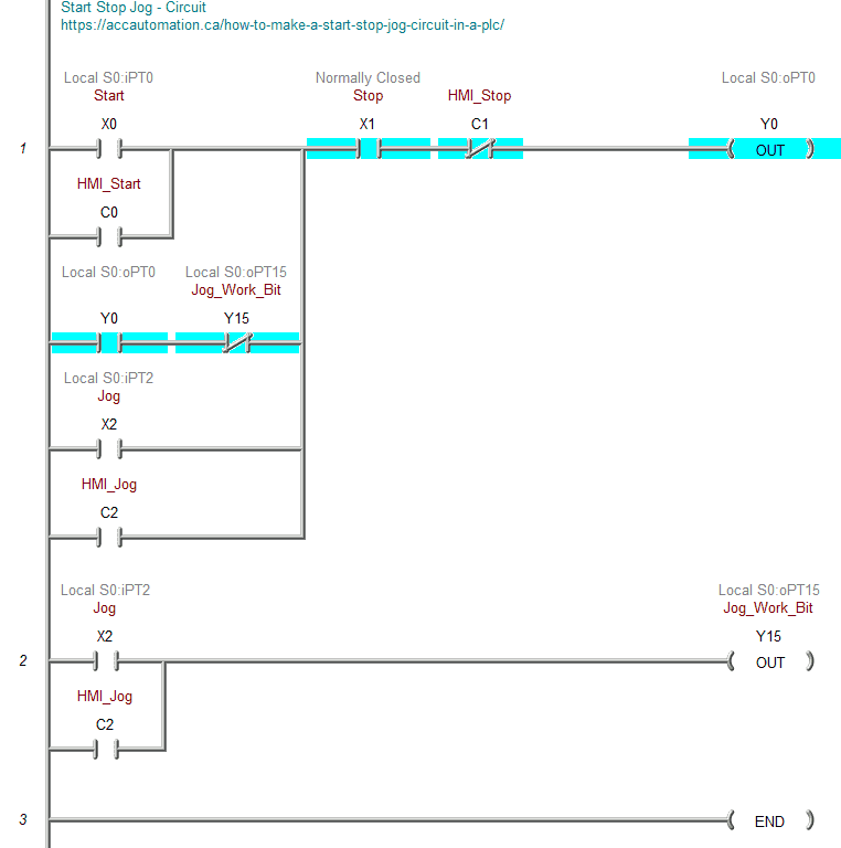
We have added the HMI control input bits C0, C1, and C2 to the circuit. The HMI stop is in series with the X1 stop input and becomes normally closed. The modified PLC program will allow the C-More CM5 HMI to control the start, stop, and jog circuit.
Export the PLC tags to use in the C-More CM5 HMI.
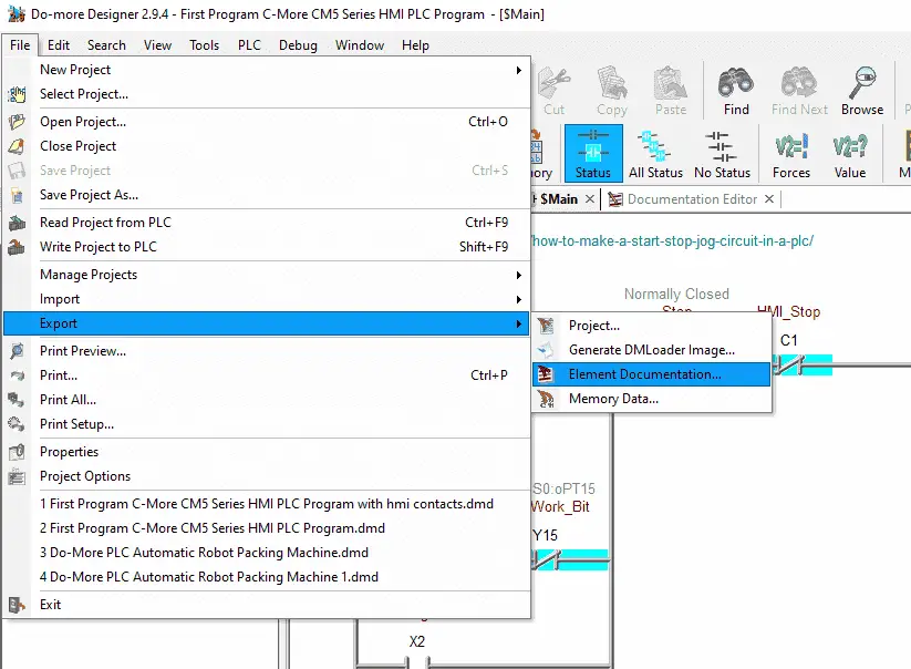
Select Element Documentation from the main menu | File | Export.
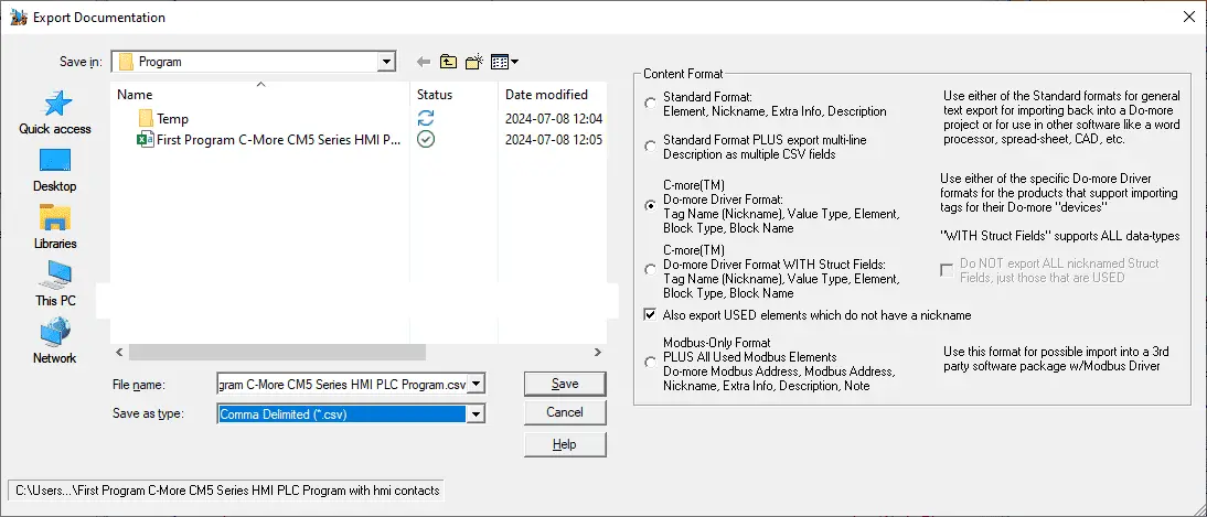
Under the content format, select the C-more(TM) Do-more Driver Format. Select also export USED elements which do not have a nickname. Give the file a name or use the default. Select save.
When designing the HMI, use the KISS method of programming. (Keep It Stupidly Simple) Consider your application’s requirements and create a user-friendly interface with easy access to the necessary controls and information.
Step 3: Program the Functionality
After designing the HMI interface, it’s time to program the functionality of the C-more CM5 HMI unit. We will first import the PLC tags into the C-more programming software.
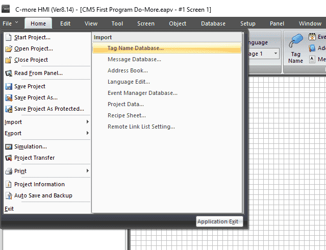
Select Tag Name Database from the main menu | File | Import.
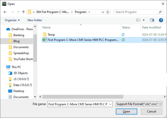
Call up the CSV file that contains the PLC tag names stored previously. Select open.
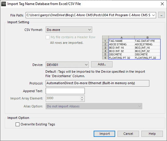
On the Import Tag Name Database window, select DEV001 for the device. You can also select “Overwrite Existing Tags” if you have previously done this and have updates. Select Import.
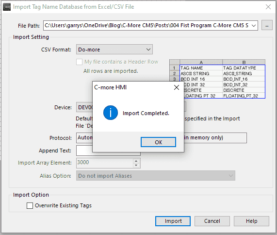
A message will be displayed after the PLC tag import has been completed. Select OK.
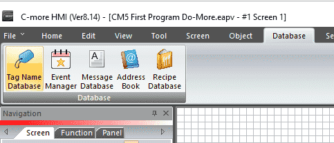
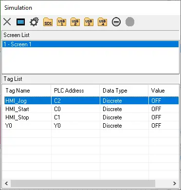
Call up the tag name database by selecting the icon on the main menu | Database.
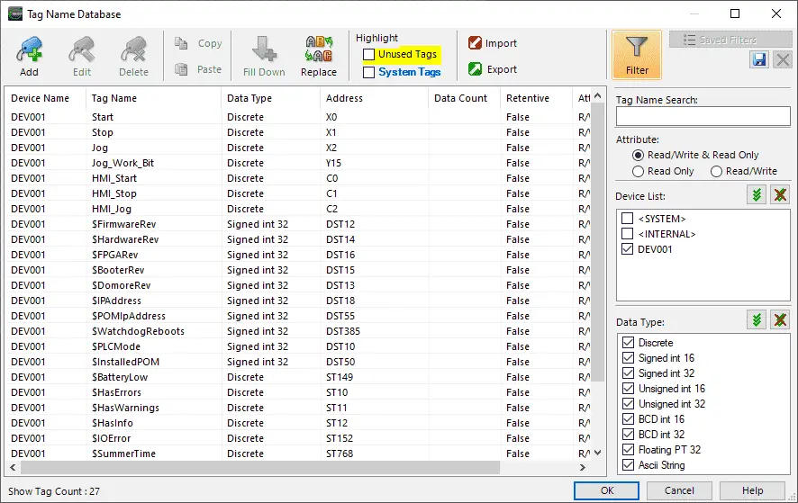
Select the filter icon from the tag name database window. Under the device list, select only DEV001. This will show only the tags we imported from the Do-More PLC. Select OK to close the window.
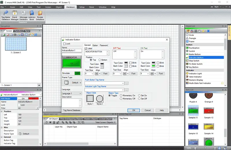
Use the software’s drag-and-drop interface to place buttons, indicators, and other elements on the HMI screen.
The built-in indicator buttons will have a separate tag for the push button and indicator lamp.
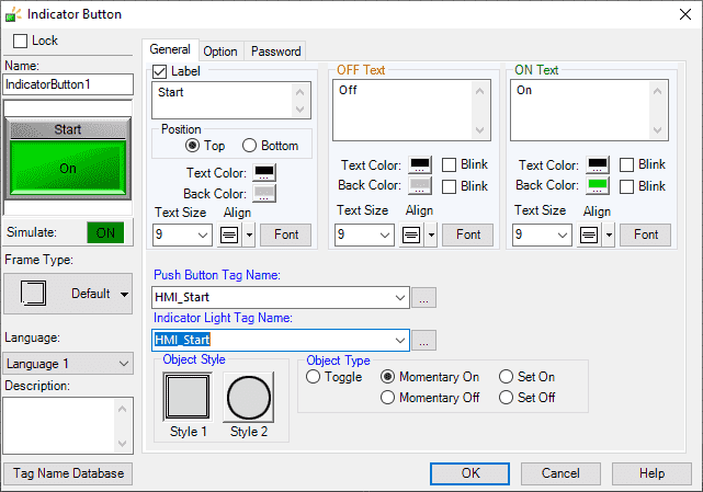
Change the label to “Start”. We will use the push button tag and the indicator lamp as the same tag. This will be “HMI_Start”. The object type will be “Momentary On.”
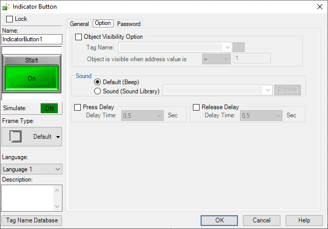
The options tab will allow you to set the object visibility, sound, press delay, and release delay. We will leave everything as their default.
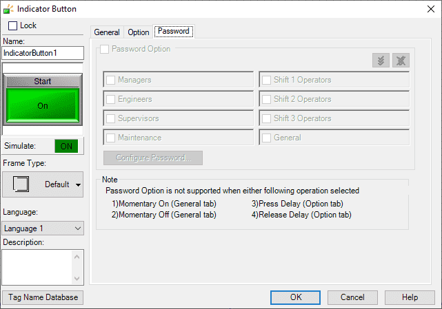
The password tab will allow you to set the password and level if applicable. Select OK.
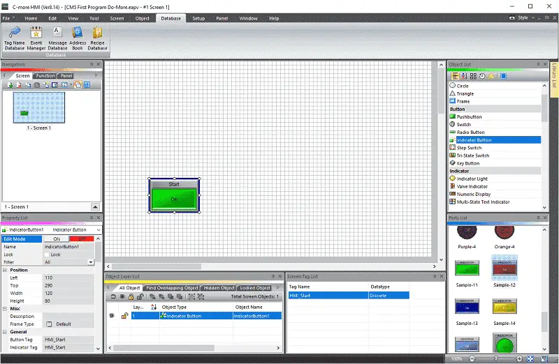
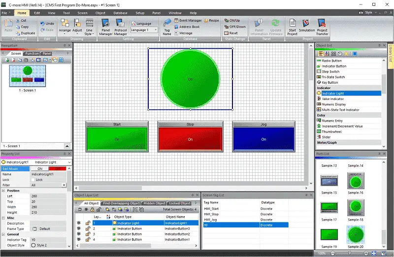
We can now move and resize the indicator button on our screen.
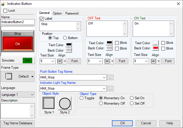
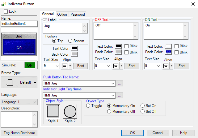
Repeat the previous steps for our Stop and Jog indicator buttons.
Once all the buttons are on the screen, you can space and move them around. Watch the video below to see how this is done.
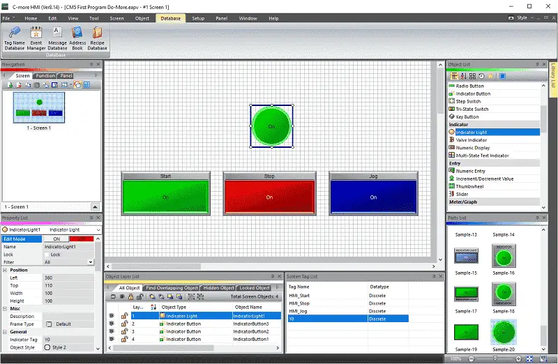
Under the object list, select Indicator Light. Click and drag Sample-20 onto the screen.
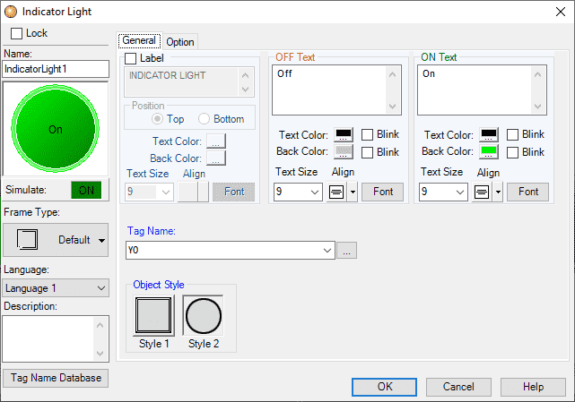
Our tag name for this light will be Y0. Select OK. Position and size the indicator lamp on the screen.
HMI programming involves designing, setting up communication with PLCs or other devices, creating alarms and notifications, and defining the behavior of various screen elements. Sometimes, you can use the software’s built-in programming tools to add logic and interactivity to the HMI interface.
Save your program.
Step 4: Test and Debug
Once the programming is complete, it’s essential to thoroughly test the HMI interface to ensure that it functions as intended. Use the simulation feature in the C-more software to test the HMI interface without the actual hardware.
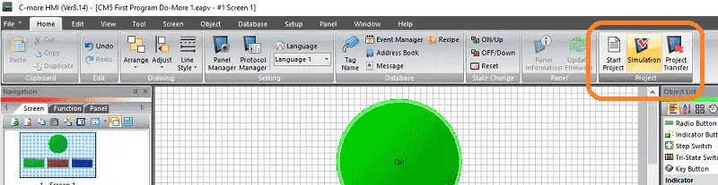
Select the Simulator icon (F5) from the main menu home tab.
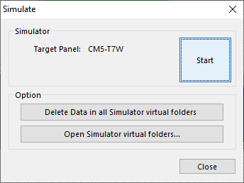
Select Start on the Simulate window.
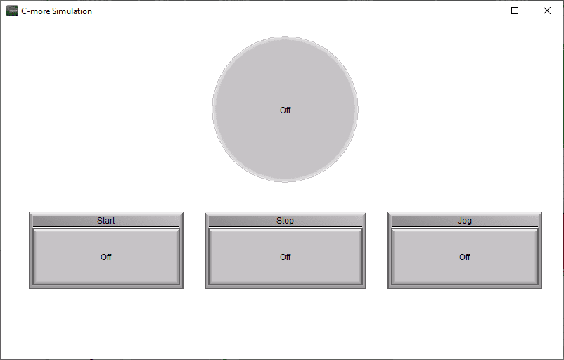
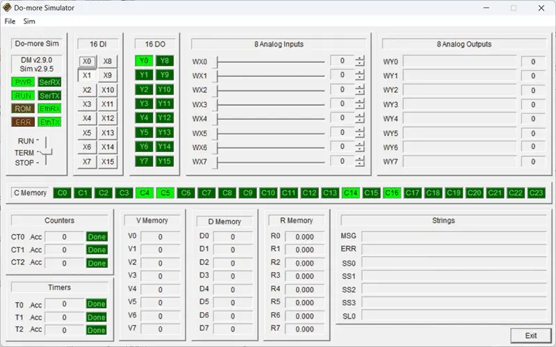
When programmed, the simulator will give a good approximation of the physical screen’s appearance. There is no communication to external devices. You can double-click on an item, which will turn on/off to show you the display. Click the X on either of the simulator’s windows to stop the simulator.
We can now download our program to the physical C-more HMI unit for further testing. Debug any issues that arise during testing and make necessary adjustments to the programming.
Step 5: Deploy the CM5 Application
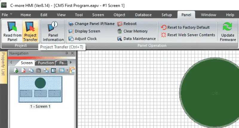
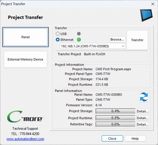
After thorough testing and debugging, deploy the HMI application to the C-more HMI unit. Select Transfer Program on the Main Menu or select Project Transfer under the Panel menu.
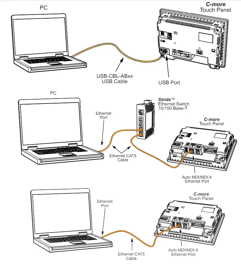
Under the transfer heading on the project transfer window, select ethernet. Select the browse button to search the network if your powered CM5 HMI is not seen. Ensure that your CM5 is connected to the PC in one of the following ways.
Select the transfer button to download the program to the CM5 HMI.
A warning message indicates that the IP address can be changed from the HMI software.
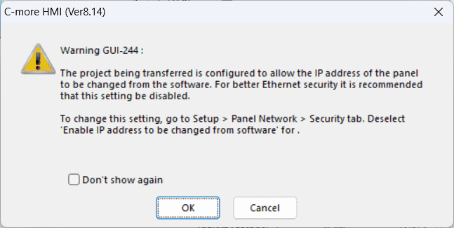
Select OK.
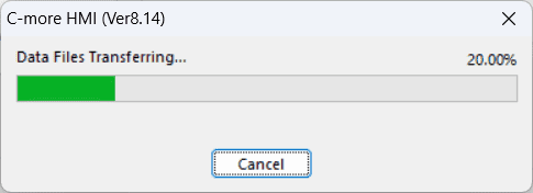
The program will be transferred.
When the download completes, a notification will be given. Select OK. Our CM5 is now programmed.
Ensure that it operates correctly in the intended environment.
Make sure that the PLC Simulator is in run mode.
Select the HMI buttons to test the program.
Programming a C-more HMI unit, such as the CM5 HMI model, involves familiarizing yourself with the programming software, designing the HMI interface, programming the functionality, testing, and debugging, and finally deploying the HMI application. You can proficiently program C-more HMI units with patience and practice and create powerful, user-friendly interfaces for various industrial applications.
Watch the video below to see the first program in our C-More CM5 HMI Panel.
Download the PLC and C-More Panel First Programs here.
Watch the video below to see the first program of the C-more CM5-T7W panel.
C-More CM5 Features:
- “4”, “7”, “10”, “12”, “15”, and “22” widescreen options
- 16.7M colors and LED backlights
- 800MHz (4″, 7″) or 1.6GHz Quad Core CPU (10″ or higher)
- 43MB project memory
- 12 to 24 VDC powered
- Built-in real-time clock with 30-day backup (no battery required)
- NEMA 4/4X (indoor use only), IP65
- FREE HMI programming software with powerful design tools and a project simulator
- CM5 series HMIs support any EA9 series project (created with V6.73 or later) for an easy panel upgrade
Frequently Asked Questions (FAQ)
Product Brochure
C-more CM5 Overview
CM5-T7W Cut Sheet – Tech Specifications / Protocols
CM5 User Manual – Hardware
CM5 Quick Start Guide
C-More Programming Software (CM5 Series)
CM5 User Manual – Software On-Line
AD C-More CM5 Sample Projects (CM5-T7W)
Watch on YouTube: First Program C-More CM5 Series HMI
If you have any questions or need further information, please contact me.
Thank you,
Garry
If you’re like most of my readers, you’re committed to learning about technology. The numbering systems used in PLCs are not difficult to learn and understand. We will walk through the numbering systems used in PLCs, including Bits, Decimal, Hexadecimal, ASCII, and Floating Points.
To get this free article, subscribe to my free email newsletter.
Use the information to inform other people how numbering systems work. Sign up now.

The ‘Robust Data Logging Easily’ eBook is also available for free download. The link is included when you subscribe to ACC Automation.