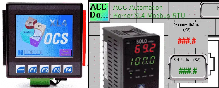
We will now communicate Modbus Serial RS485 from the Horner Master controller to the Solo process temperature controller. The Horner APG XL4 all in one controller has several different ports for communications. We have both serial and Ethernet-type ports that can be used for many different protocols. These protocols can be downloaded from the Horner APG website and transferred into the controller. We will be looking at the Modbus RTU protocol. Using the serial RS485 port on the XL4 we will communicate to a Solo process temperature controller. We will read the process value (PV) into the Horner APG XL4 controller and write the set value (SV) back into the process temperature controller. This is all accomplished without any ladder logic in the PLC. The Horner APG XL4 is one of the easiest networks to set up.
Previously we discussed the following in our Horner XL4 Series:
System Hardware
Installing the Software Cscape
Cscape Software Setup
Establishing Communication
Numbering System and Addressing
User Interface
Timers and Counters
Compare and Move Instructions
Math Instructions
Program Control Instructions
Rotate and Shift Register
Recipe Instruction
Report Generator
There are three steps to making the Horner APG XL4 controller communicate to the Solo Process Temperature Controller. We will wire the RS485 communication cable between the units. Set the parameters in the Solo process temperature controller. Then we will set the parameters in the Horner APG XL4 controller.
Here are a couple of links to explain the modbus protocol. They are an excellent reference for Modbus TCP, Modbus RTU, Modbus ASCII.
http://www.rtautomation.com/technologies/modbus-rtu/
http://www.simplymodbus.ca/FAQ.htm
Wiring Communication RS485 – Horner Modbus RTU
Modbus RTU protocol works on RS485. This serial communication has two wires.
The following is the diagram for the XL4 serial port.
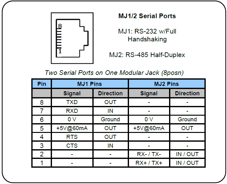 Notice that the RS232 and RS485 are located on the same modular jack. We will be using MJ2 pins 1 and 2 for communication. The maximum distance for RS485 is 1220m. You can put up to 32 units on this bus.
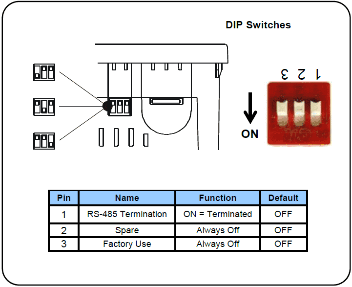
A terminating resistor should be on each end of this parallel bus system. The XL4 accomplishes this by including a switch.
Here is the wiring of the solo.
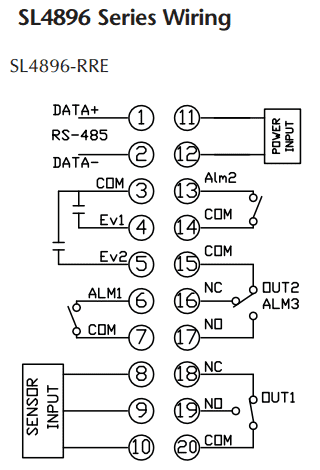
You will see that we use terminals 1 and 2. Data + is wired to Data + and Data – is wired to Data -.
Setting the Solo Process Temperature Controller – Horner Modbus RTU
The solo process temperature controller needs to be set up before we can communicate to it. The default setting is ‘Off’ for the On-Line Configuration. Here is the way to change into the different modes in the Solo.
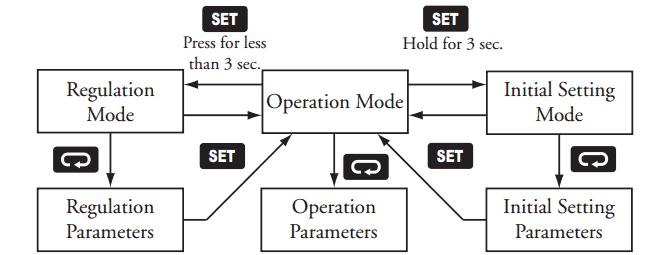
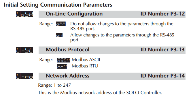
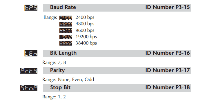
In the Initial Setting Mode we will change the online configuration to on and make the changes to the Modbus settings as follows: 9600 Baud, Even, 8 Data Bits, 1 Stop Bit, Modbus RTU Format. We will leave the default unit number as 1.
 Our controller is now set to communicate.
Download the documentation and/or configuration and monitoring software at the following URL link:
http://support.automationdirect.com/products/solo.html
Modbus RTU (Addresses) – Horner Modbus RTU
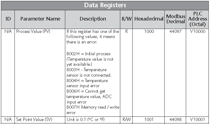
The following addresses will be used in our project:
For a list of all Modbus addresses that can be used in your project, refer to the Solo Manual located at the URL above.
Setting up the Horner APG XL4 Controller – Horner Modbus RTU
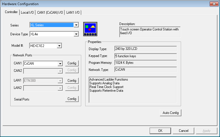
We will now set up the XL4 PLC controller. Call up the hardware configuration by using the main menu Controller | Hardware Configuration… You can also achieve this by using the project navigator and selecting Hardware Configuration.
Select ‘Config” beside the Serial Ports.
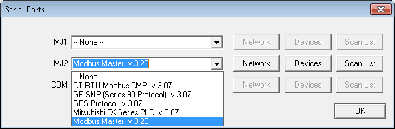
Select ‘Modbus Master v 3.20’ for MJ2 (RS485).
Now select Network beside the MJ2 port selection.
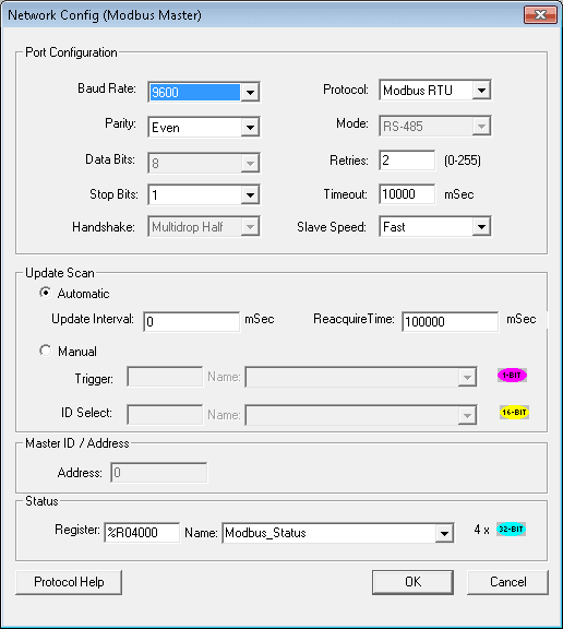
We now configure the serial port with the same parameters that we used for the Solo unit.
9800 baud, Even parity, 8 data bits, 1 stop bit and Modbus RTU protocol.
The timeout and slave speed can be left as default.
We will leave the update scan section as default.
We can now set the status register to %R04000.
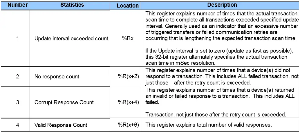
The following table will show the meaning of the status register we just assigned.
Hit OK to bring us back to the serial port settings
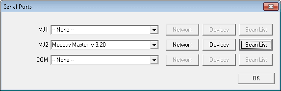
Now select Devices beside the MJ2 port selection.
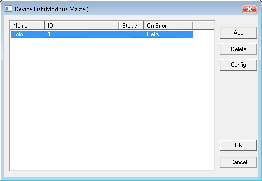
This is where we will add our devices to the network. In our case, we have only one solo unit to add. Select Add.
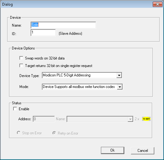
We will enter the name Solo and set the ID to 1. (Slave Address)
Leave all other parameters to their default.
Select OK and you will see the device now in the device list.
Select OK to go back to the serial port window.
Select Scan List beside the MJ2 port selection.
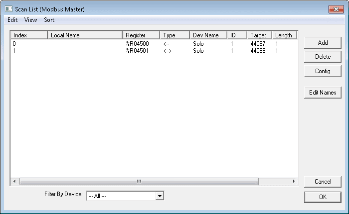
This brings up a list that the Modbus master will scan. In our case, we will have a reading of the present value (PV) and the read/write of the set value (SV).
Select the add button to request the information.
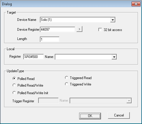
The target will be Solo(1). This is slave unit number 1. The device register will be 44097. This is the present value of the solo and it is only 1 register in length.
We will store this information in our local register %R04500.
The update type will be a ‘Polled Read’.
Hit OK to see this in our list.
We will now set up the read/write to the process value of the solo.
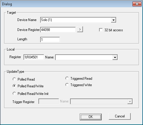
The target is still Solo(1). The device register will be 44098. This is the set value of the solo process temperature controller. It is also 1 register in length.
We will store and retrieve the set value (SV) in local register %R04501.
The update type will be a ‘Polled Read/Write”
Hit OK to see this in our list.
Select OK and we will be returned to our serial port window.
All of our setups is complete for the serial port to communicate to the solo unit using Modbus RTU protocol.
We will add a screen to the Horner APG XL4 OCS controller so we can see the present value and change the set value from the HMI.
Our screen is as follows:
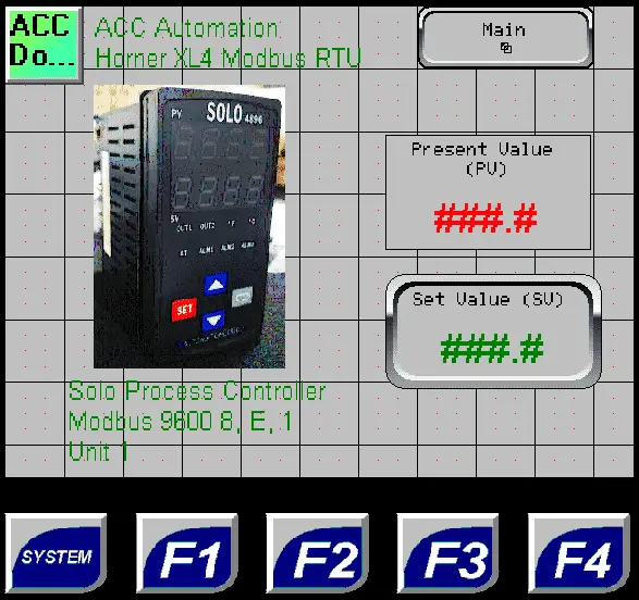
Note: PV value comes from %R04500. SV value is read/written to %R04501.
See this logic in action by watching the YouTube video below.
You can download this application here. It will contain all of the screens and logic programming.
All of the documentation for the XL4 can be downloaded at the following URL:
https://hornerautomation.eu/product/xl4-prime-ocs-3-5-colour-touchscreen/
Next time we will look at using FTP (File Transfer Protocol) in the Horner APG XL4 OCS.
Watch on YouTube: Horner XL4 Modbus RTU Instructions
If you have any questions or need further information please contact me.
Thank you,
Garry
If you’re like most of my readers, you’re committed to learning about technology. Numbering systems used in PLCs are not difficult to learn and understand. We will walk through the numbering systems used in PLCs. This includes Bits, Decimal, Hexadecimal, ASCII, and Floating Point.
To get this free article, subscribe to my free email newsletter.
Use the information to inform other people how numbering systems work. Sign up now.

The ‘Robust Data Logging for Free’ eBook is also available as a free download. The link is included when you subscribe to ACC Automation.