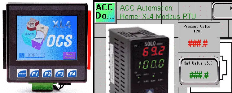
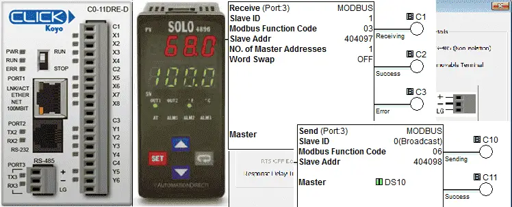
We will now communicate Modbus Serial RS485 from the Horner Master controller to the Solo process temperature controller. The Horner APG XL4 all in one controller has several different ports for communications. We have both serial and Ethernet-type ports that can be used for many different protocols. These protocols can be downloaded from the Horner APG website and transferred into the controller. We will be looking at the Modbus RTU protocol. Using the serial RS485 port on the XL4 we will communicate to a Solo process temperature controller. We will read the process value (PV) into the Horner APG XL4 controller and write the set value (SV) back into the process temperature controller. This is all accomplished without any ladder logic in the PLC. The Horner APG XL4 is one of the easiest networks to set up. Continue Reading!
Tag Archives: modbus rtu programming
Click PLC Send and Receive Instructions
Receive and Send instructions will allow you to send and receive serial data to an external device. The communication method that you setup can be ASCII or Modbus. ASCII (American Standard Communication for Information Interchange) can be used to send to devices such as a printer. Receiving ASCII can be used for connecting barcode scanners to the PLC. The barcode will be read as an ASCII string in the PLC. Modbus serial communication (Modbus RTU) is a standard protocol used in many automation devices. We will demonstrate the Send and Receive instruction by communicating Modbus to a Solo Temperature Controller. Our example will read the current process (PV) value and write the set point value (SV) in the controller. Keep on Reading!
USB to RS485 PC Adapter Installation
We will be installing a USB to rs485 installation on our computer. The USB-485M is a 2-wire USB to RS-485 serial communication adapter for RS485 use. It does not require an external power supply or complicated configuration.
It has a Type A (plug) USB connector for the computer side and a universal female RJ45/RJ12 modular connector. This will accept RJ12 and RJ45 plugs. The USB-485M supports multiple baud rates and is USB V2.0 Compliant.
Installing the Driver on PC
Do NOT connect the USB-485M to your PC before installing the driver file.
Go to the Automation Direct website and download the latest drivers for this device. I would not use the mini-CD that came with the converter because it may be outdated.
USB-485M Serial Converter Support Resources
Download and extract the zip file. (Right-click on the zip file and select Extract All…. )
If you have a 64bit computer, double click on the following file:
CP210xVCPInstaller_x64.exe
If you have a 32bit computer, double click on this file:
CP210xVCPInstaller_x86.exe
If you are unsure about a 32-bit or 64-bit computer, go to the control panel and look under the system. Under System type, it will display either a 32-bit Operating or 64-bit Operating system.
Alternatively, on Windows 7, you can click Start and right-click on Computer.
Selecting properties will call up the system information for you.
This will now start the installation of the CP210x USB to the UART Bridge Driver. Select Next.
You must accept the license agreement before the software will install. Select ‘I accept this agreement and hit Next.
You will now get a message that the installation is complete. The Silicon Laboratories PC Driver is now installed. Click Finish.
We will now configure the device driver for our hardware.
Connect the USB 485M to your PC.
The driver software on our PC installation will begin by searching for the CP2103 USB to UART Bridge Controller. It will start by exploring the windows update…
Once the software has been configured on the PC, a message will be displayed. If it cannot find the driver software, you can manually select the x64 (64bit) or x86 (32bit) folders from the downloaded driver files.
You can now call up the device manager and view the ports on your computer. The Silicon Labs CP210x USB to UART Bridge is on communication port 5. COM5 will now point to the USB port where the information is converted to an RS485 signal.
We are now ready to connect to our equipment with the USB to RS485 converter. Since this is a serial device and is a 1: N connection, we will have a master and at least one slave unit. The master is usually the PC (personal computer) that will control all communication. It will request information and receive answers. All communication must have the same parameters when communicating. What separates the transmission is that each slave is assigned a unique number.
Example:
Device | Computer ‘Master’ | Solo Process Controller ‘Slave’ |
Do-More PLC ‘Slave’ |
Additional Devices ‘Slaves’ |
Station Address / Unit number | N/A | 1 | 2 | … |
Baud Rate | 9600 | 9600 | 9600 | 9600 |
Data Bits | 8 | 8 | 8 | 8 |
Parity | Even | Even | Even | Even |
Stop Bits | 1 | 1 | 1 | 1 |
The protocol is the actual communication (Information format transferred) over the network. (Master to Slaves) The media is the RS485 serial cable itself.
Watch on YouTube: USB to RS485 PC Adapter Installation
If you have any questions or need further information, please contact me.
Thank you,
Garry
If you’re like most of my readers, you’re committed to learning about technology. Numbering systems used in PLCs are not challenging to learn and understand. We will walk through the numbering systems used in PLCs. This includes Bits, Decimal, Hexadecimal, ASCII, and Floating Point.
To get this free article, subscribe to my free email newsletter.
Use the information to inform other people how numbering systems work. Sign up now.
The ‘Robust Data Logging for Free’ eBook is also available for free download. The link is included when you subscribe to ACC Automation.
How to Implement Modbus TCP Protocol VBA Excel
We will use Visual Basic for Applications (VBA) to communicate to a PLC using Modbus TCP protocol. Reading ten registers in the PLC and displaying a bar graph in Excel. Previously we have used VB6 to communicate Modbus TCP.
Sequence for Modbus TCP on Excel using VBA
The following steps will be done:
- Explain Modbus TCP protocol
- Install OstroSoft Winsock Component
– Winsock API Calls for communication on network - Develop the Excel and VBA application
(Microsoft Excel 2010) - Communicate to the PLC and sample code
(Do-More Simulator)
What is Modbus TCP (Ethernet)
The Modbus TCP/IP or Modbus TCP is a protocol that is used for communications over TCP/IP networks. This is done on port 502. Modbus TCP does not require a checksum calculation as lower layers already provide checksum protection. You can think of this as a letter being sent and Ethernet TCP/IP acts like an envelope for the Modbus Commands. I will not go into the details of the communication protocol but here are some links to references:
Introduction to Modbus TCP/IP
Simply Modbus – Modbus TCP
Winsock Component – Excel VBA Modbus TCP
OstroSoft Winsock Component
OSWINSCK.dll serves as a wrapper for the Winsock API and helps programmers to abstract from the complexity of API calls and focus on application functionality. Works with programming and scripting languages supporting COM.
You will need to download and install the OstroSoft Winsock Component on your computer.
For use with .NET, Visual Basic 4 or 5, Visual C++, ASP, VBA, VBScript, JavaScript, or any other language, supporting COM:
1. Download oswinsck.exe
2. Run the downloaded file from Windows Explorer or command-line
Hit OK
I use the default directories where the program will be installed. Click the button to install.
Leave the program group to the default so I know what the program is after installation. Click continue.
Click OK
The OstroSoft Winsock Component is now installed.
Start Microsoft Excel
Select ‘Developer’ along with the top tabs.
If the Developer tab is not present then we must turn on the developer tab.
Select File | Options Select ‘Customize Ribbon’
Check the ‘Developer’ under Main Tabs.
Under the Developer menu. Select ‘Visual Basic’
The Visual Basic Editor window will now be displayed.
From the menu – Tools | References
We can now add the OstroSoft Winsock Component to our application.
Select OK
Select Sheet1(Sheet1).
Visual Basic Code – Excel VBA for Modbus TCP
Now put the visual basic code in the Sheet1(Sheet1)
Here is the code:
‘This example uses OstroSoft Winsock Component
‘http://www.ostrosoft.com/oswinsck.asp
Option Explicit
Dim bytesTotal As Long
Dim sPage As String
Dim MbusQuery
Dim returnInfo
Dim wsTCPgdb
Dim WithEvents wsTCP As OSWINSCK.Winsock
Dim SetObject
Dim RetrieveData
Private Sub CommandButton1_Click() ‘ Retrieve Data
On Error GoTo ErrHandler
Dim sServer As String
Dim nPort As Long
Dim StartTime
DoEvents
nPort = 502 ‘ See configuration in Do-More Designer
‘ Set the IP address of the PLC
sServer = Sheets(“Sheet1”).Range(“B4″) ‘”192.168.1.3”
RetrieveData = 1
CommandButton1.BackColor = “&H0000FF00” ‘ Set colour to Green
‘Check to see if the object has been created. If not set wsTCP.
If SetObject = “” Then
Set wsTCP = CreateObject(“OSWINSCK.Winsock”)
wsTCP.Protocol = sckTCPProtocol
SetObject = 1
End If
‘ Check the state of the TCP connection
‘0 sckClosed connection closed
‘1 sckOpen open
‘2 sckListening listening for incoming connections
‘3 sckConnectionPending connection pending
‘4 sckResolvingHost resolving remote host name
‘5 sckHostResolved remote host name successfully resolved
‘6 sckConnecting connecting to remote host
‘7 sckConnected connected to remote host
‘8 sckClosing Connection Is closing
‘9 sckError error occured
‘ If TCP is not connected, try to connect again.
If wsTCP.State <> 7 Then
If (wsTCP.State <> sckClosed) Then
wsTCP.CloseWinsock
End If
‘ Open the connection
wsTCP.Connect sServer, nPort
StartTime = Timer ‘ Use the timer to determine if a connection cannot be made
Do While ((Timer < StartTime + 2) And (wsTCP.State <> 7))
DoEvents
Loop
If (wsTCP.State = 7) Then
Else
Exit Sub
End If
End If
‘ If we are connected then request the information.
If (wsTCP.State = 7) Then
MbusQuery = Chr(0) + Chr(0) + Chr(0) + Chr(0) + Chr(0) + Chr(6) + Chr(0) + Chr(3) + Chr(0) + Chr(0) + Chr(0) + Chr(20)
wsTCP.SendData MbusQuery ‘Send out the Modbus Information
‘ Read the information
‘0000: Transaction Identifier
‘0000: Protocol Identifier
‘0006: Message Length (6 bytes to follow)
’00: The Unit Identifier
’03: The Function Code (read MHR Read Holding Registers)
‘0000: The Data Address of the first register
‘0020: The number of bytes to read
‘ Write the information
‘0000: Transaction Identifier
‘0000: Protocol Identifier
‘0009: Message Length (6 bytes to follow)
’01: The Unit Identifier
’16: The Function Code (read Analog Output Holding Registers)
‘0000: The Data Address of the first register
‘0001: The number of registers to write
’02: The number of data bytes to follow
‘0030 The number to put into the register
‘ Note: Addresses are offset by 1
‘ Example: MHR1 = Address 0000
‘ Example: MHR30 = Address 0029
End If
Exit Sub
ErrHandler:
MsgBox “Error ” & Err.Number & “: ” & Err.Description
End Sub
Private Sub CommandButton2_Click() ‘ Stop the communication
RetrieveData = 0
CommandButton1.BackColor = “&H8000000F” ‘ Set the default colour
End Sub
Private Sub wsTCP_OnDataArrival(ByVal bytesTotal As Long)
Dim sBuffer
Dim i
Dim MbusByteArray(500)
Dim h As Integer
Dim txtSource
wsTCP.GetData sBuffer
txtSource = txtSource & sBuffer
Dim j As Byte
returnInfo = “”
For i = 1 To bytesTotal
wsTCP.GetData j, vbByte
MbusByteArray(i) = Asc(Mid(sBuffer, i, 2))
returnInfo = returnInfo & Asc(Mid(sBuffer, i, 2))
Next
txtSource = returnInfo
txtSource = Val(Str((MbusByteArray(10) * 256) + MbusByteArray(11)))
Sheets(“Sheet1”).Range(“B10”) = Val(Str((MbusByteArray(10) * 256) + MbusByteArray(11)))
Sheets(“Sheet1”).Range(“B11”) = Val(Str((MbusByteArray(12) * 256) + MbusByteArray(13)))
Sheets(“Sheet1”).Range(“B12”) = Val(Str((MbusByteArray(14) * 256) + MbusByteArray(15)))
Sheets(“Sheet1”).Range(“B13”) = Val(Str((MbusByteArray(16) * 256) + MbusByteArray(17)))
Sheets(“Sheet1”).Range(“B14”) = Val(Str((MbusByteArray(18) * 256) + MbusByteArray(19)))
Sheets(“Sheet1”).Range(“B15”) = Val(Str((MbusByteArray(20) * 256) + MbusByteArray(21)))
Sheets(“Sheet1”).Range(“B16”) = Val(Str((MbusByteArray(22) * 256) + MbusByteArray(23)))
Sheets(“Sheet1”).Range(“B17”) = Val(Str((MbusByteArray(24) * 256) + MbusByteArray(25)))
Sheets(“Sheet1”).Range(“B18”) = Val(Str((MbusByteArray(26) * 256) + MbusByteArray(27)))
Sheets(“Sheet1”).Range(“B19”) = Val(Str((MbusByteArray(28) * 256) + MbusByteArray(29)))
DoEvents
‘ Determine if we retrieve the data again.
If RetrieveData = 1 Then
Call CommandButton1_Click
End If
End Sub
Private Sub wsTCP_OnError(ByVal Number As Integer, Description As String, ByVal Scode As Long, ByVal Source As String, ByVal HelpFile As String, ByVal HelpContext As Long, CancelDisplay As Boolean)
MsgBox Number & “: ” & Description
End Sub
Private Sub wsTCP_OnStatusChanged(ByVal Status As String)
Debug.Print Status
End Sub
Note: The program utilizes the CHR and STR functions to convert the data from binary to ASCII and back.
The highest value of a byte of data is 256. This is why we have to multiply the highest significant byte with 256
Interface:
Go back to Sheet1 and we can now put on the worksheet what we would like to see.
Note the following:
IP Address = B4
MHR 1 to 10 values located at B10 to B19
‘Stop Data’ – CommandButton2
‘Retrieve Data’ – CommandButton1
Communication to the PLC
Start the Do-More Designer software.
Under the Project Browser select ‘System Configuration’
Make note of the IP address. If you are running the simulator then this is automatically filled in.
Ensure that the Enable Modbus/TCP Server is checked. Also make sure that the TCP Port Number is 502.
The sample PLC program will write values in the range from 0 to 4000. These values will be put in MHR 1 to MHR 10.
Here is the first couple of rungs of the PLC program. It will use clock bit flags to increment the MHR 1 channel. When it gets to the value above 4000, a move instruction will put a 0 back into MHR 1.
If input X0 turns on then the value in XW0 will be moved into MHR1 and the previous clock bit will not be in effect. Values will be between 0 and 4096. (12-bit resolution)
This is repeated with different internal clock bit flags up to MHR10.
Running the program will produce the following:
As you can see the Modbus TCP protocol is easy to implement with visual basic for applications.
Download the PLC program and Excel file.
Additional Information:
Excel – Conditional Movement of Data
Watch on YouTube: How to Implement Modbus TCP Protocol using VBA with Excel
If you have any questions or need further information please contact me.
Thank you,
Garry
If you’re like most of my readers, you’re committed to learning about technology. Numbering systems used in PLC’s are not difficult to learn and understand. We will walk through the numbering systems used in PLCs. This includes Bits, Decimal, Hexadecimal, ASCII and Floating Point.
To get this free article, subscribe to my free email newsletter.
Use the information to inform other people how numbering systems work. Sign up now.
The ‘Robust Data Logging for Free’ eBook is also available as a free download. The link is included when you subscribe to ACC Automation.