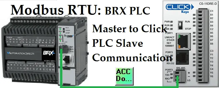
Recently I was asked to demonstrate communication between a BRX PLC and Click PLC using Modbus RTU. Both PLCs are available from automation direct com. Modbus serial communication (Modbus RTU) is a standard protocol used in many automation devices. It works on a Master / Slave configuration. You can have only one master per network on Modbus RTU (Remote Terminal Unit). A maximum of 32 devices (Nodes) on the network can communicate to the master. A review of the Modbus RTU protocol (RTU frames) can be seen at the following URL.
http://www.rtautomation.com/technologies/modbus-rtu/
Using the BRX PLC as a Master, we will be communicating to the Click PLC (Slave). Our example will read 10 registers from the Click PLC and write 10 registers from the BRX PLC. Let’s get started!
This post is part of our BRX Series PLC. Here are some of the topics that we have already covered in this series.
System Hardware – Video
Unboxing – Video
Installing the Software – Video
Establishing Communication – Video
Firmware Update – Video
Numbering Systems and Addressing – Video
First Program – Video
Monitoring and Testing the Program – Video
Online Editing and Debug Mode – Video
Timers – Video
Counters – Video
High-Speed IO – Video
Hardware – Modbus RTU BRX Do-More to Click
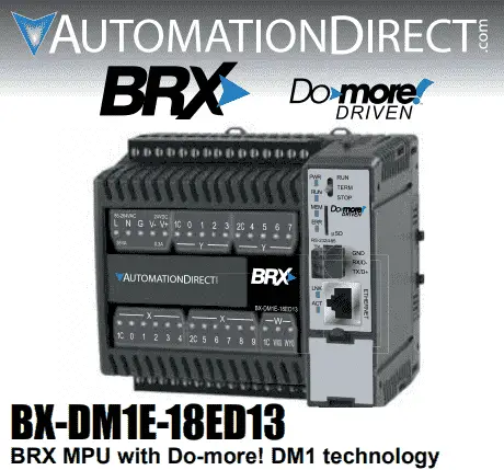
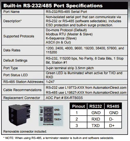
Our BRX PLC comes with a built in RS485 port that we will be using for a Modbus RTU master unit. Here are the specifications for the port.
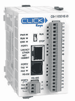
The Click PLC that we will be using also comes with a RS485 port. We will be using Modbus RTU protocol to communicate from the BRX PLC to the Click PLC.
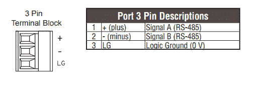
Com Port 3 of the Click supports 2-wire RS-485
Wiring – Modbus RTU BRX Do-More to Click
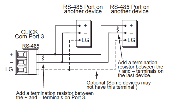
RS485 is a two wire communication. You daisy chain the devices along the path until you get to the end of the chain where a termination resistor is placed between the + and – terminals. The BRX PLC has the ability to add the termination resistor in the software.
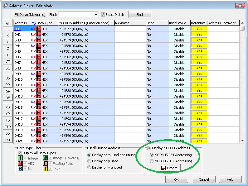
Addressing – Modbus RTU BRX Do-More to Click
The Click PLC has an address picker. You can enable the ‘Display MODBUS Address’ to see the addresses for each of the memory areas.
Modbus addressing for the BRX PLC is located in a separate memory area. BRX PLC is part of the Do-More family of controllers. See the following chart for the Modbus addresses. We are using the BRX as a master so we can move the information write the information to any memory location after communication.
| Coil/Register Numbers | Data Addresses | Type | BRX (Do-More) PLC | Table Name |
| 00001-09999 | 0000 to 270E | Read-Write | MC1 to MC1023 | Discrete Output Coils |
| 10001-19999 | 0000 to 270E | Read-Only | MI1 to MI1023 | Discrete Input Contacts |
| 30001-39999 | 0000 to 270E | Read-Only | MIR1 to MIR2047 | Analog Input Registers |
| 40001-49999 | 0000 to 270E | Read-Write | MHR1 to MHR2047 | Analog Output Holding Registers |
We will be using the Modbus network write and Modbus network read commands in the BRX PLC. Ten registers will be read and written according to the chart below.
| Controller | Modbus Address | BRX (Do-More)PLC | Click Address | Comment |
| BRX Write | 424577 – 424586 | MHR1 to MHR10 | DH1 to DH10 | Write 10 registers to the Click PLC |
| BRX Read | 424587 – 424596 | MHR11 to MHR20 | DH11 to DH20 | Read 10 registers from the Click PLC |
Click PLC Configuration
The Click PLC can be programmed using free Click programming software from Automation Direct. Here is a link to the software.
http://support.automationdirect.com/products/clickplcs.html
The following links will help you to install the software and establish communication.
https://accautomation.ca/click-plc-installing-the-software/
https://accautomation.ca/click-plc-establish-communication/
We will go online with the Click PLC and call up our Com Port Setup…
Main Menu | Setup | Com Port Setup…
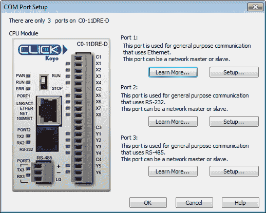
Under Port 3 select Setup…

We will now set the communication settings in our modbus slave unit.
Unit ID: 1 – This is the unit identification on the network
Baud Rate: 38400
Data Bits: 8
Stop Bits: 1
Parity: Odd
Select OK once the settings have been changed. We can then select OK on the COM Port Setup window to close it.
Click PLC Program
Since the Click PLC is acting as a slave it will not require any ladder programming for the communications to work. We will be putting in a rung to demonstrate that the communication link is active.
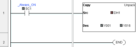
You will see that we use a copy instruction to copy the bits in DH1 (First register that the BRX will write information) to the physical outputs Y001 to Y0016.
We will also set up a data view window to view our information being transmitted.
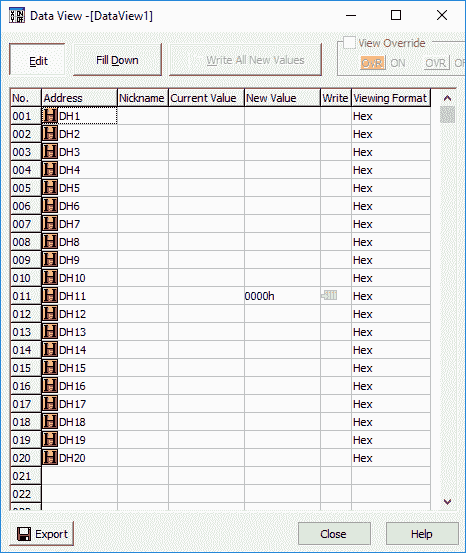
The first 10 registers are written from the BRX PLC and the next is read to the BRX PLC.
We have now finished setting up our Click PLC Slave unit.
BRX PLC Configuration
The BRX PLC can be programmed using free Do-More Designer software from Automation Direct. Here is a link for the software which includes a simulator.
http://support.automationdirect.com/products/domore.html
The following links will help you to install the software and establish communication.
https://accautomation.ca/brx-plc-installing-the-software/
https://accautomation.ca/brx-plc-establishing-communication/
We will go online with our controller and call up the system configuration window.
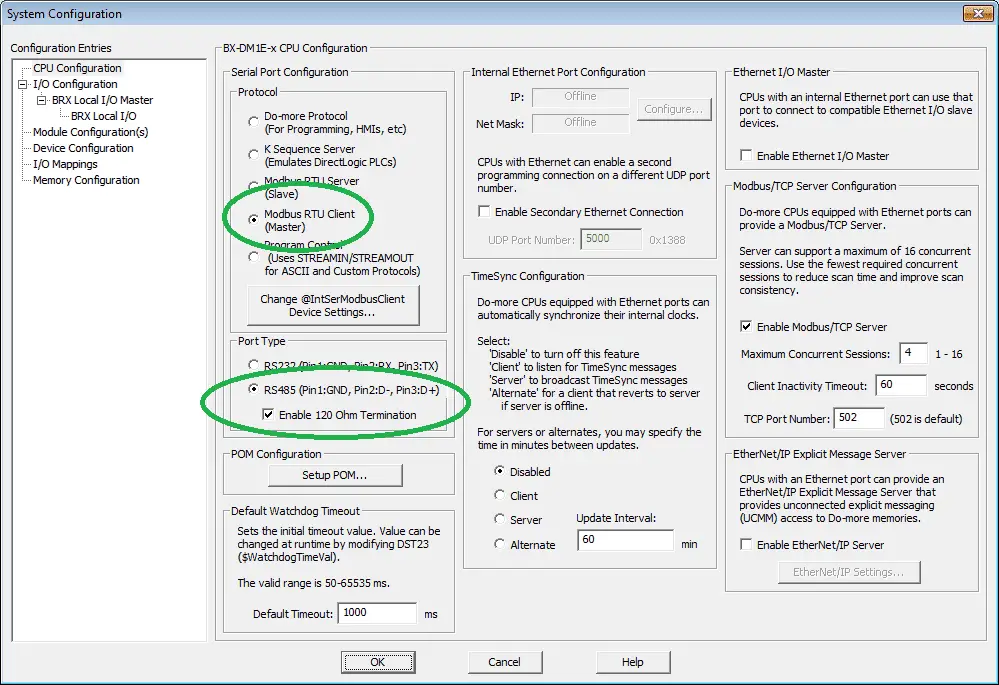
Ensure that under the Serial Port Configuration we have Modbus RTU Client (Master) selected. Also under Port Type we have the RS485 selected and enable the 120 Ohm Termination.
Select the “Change @IntSerModbusClient”
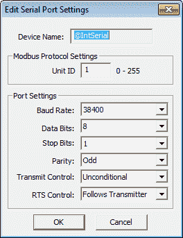
We can now set up the parameters for the serial port on the BRX PLC.
Unit ID: 1 – Left as default (Master does not require this setting)
Baud Rate: 38400
Data Bits: 8
Stop Bits: 1
Parity: Odd
Note: It is important to have all of these parameters set the same on each side or you will not communicate.
Select OK once these parameters have been set. Select OK again to exit from the system configuration menu.
BRX Ladder Program
We will be using the Modbus network write and read instructions in the BRX PLC to get the information (receive) and write the information (send) using Modbus RTU.
The Modbus Network Write instruction will write the first 10 words from the BRX PLC to the Click PLC. See the table above for the addresses.
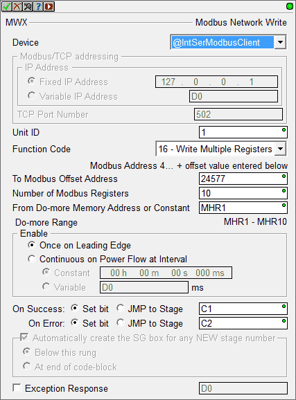
We are writing to unit ID 1 that was set up in our Click configuration. Using function code 16 (Write Multiple Registers) we are writing 10 registers starting at 24577 in the Click. The information is coming from the Do-More register starting at MHR1. We trigger this instruction once on a leading-edge signal.
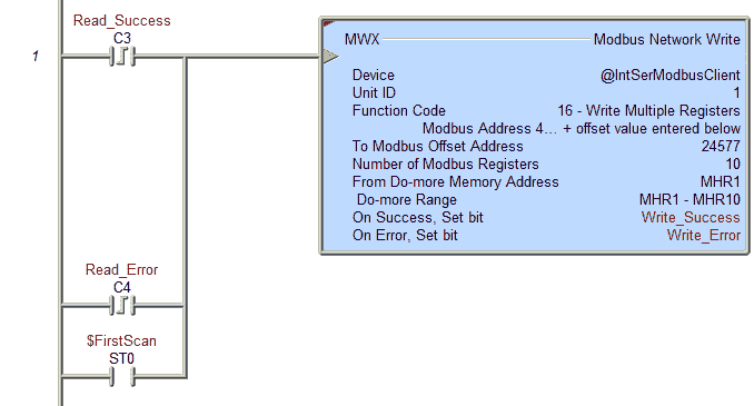
You will notice that we have the first scan flag bit like a start condition. This will automatically start the communications when power is applied or the PLC is switched from program to run mode.
The other conditional bits are from our Modbus Network Read instruction. Read_Success or Read_Error will also trigger our instruction.
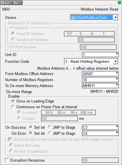
Function code 3 (Read Holding Registers) is used to read 10 registers from the Click PLC starting at 24587. They are then placed in the BRX PLC memory starting at MHR11.
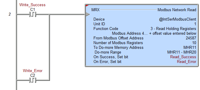
Write_Success and Write_Error bits from the Modbus Network Write instruction will trigger our Modbus Network Read instruction.
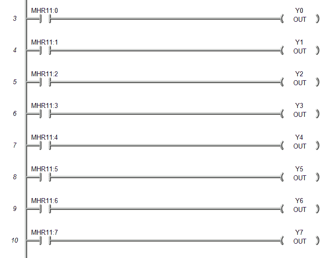
This code will take the first 8 bits of the first register that we read from the Click PLC and turn on the physical outputs of our BRX PLC. We will then see the information changing.
Save the program and download it to the controller. We can then put the BRX PLC in run mode and execute our ladder program.
Calling the Data View in the Do-More programming software, we can then monitor and set the information that we are now exchanging with the CLick Series PLC.
See this program in action by watching the video below.
You can download both PLC programs here.
Watch on YouTube: Modbus RTU BRX PLC Master to Click PLC Slave Communication
If you have any questions or need further information please contact me.
Thank you,
Garry
If you’re like most of my readers, you’re committed to learning about technology. Numbering systems used in PLC’s are not difficult to learn and understand. We will walk through the numbering systems used in PLCs. This includes Bits, Decimal, Hexadecimal, ASCII and Floating Point.
To get this free article, subscribe to my free email newsletter.
Use the information to inform other people how numbering systems work. Sign up now.

The ‘Robust Data Logging for Free’ eBook is also available as a free download. The link is included when you subscribe to ACC Automation.