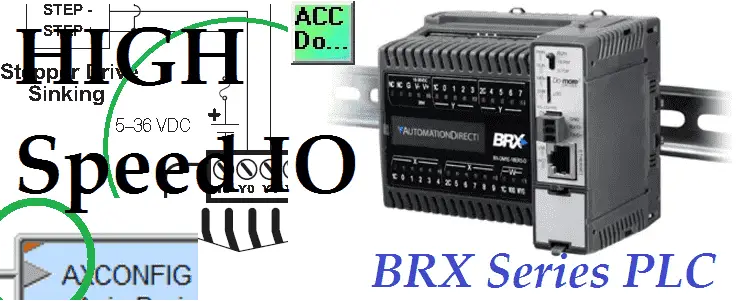
The BRX Do-More series of programmable logic controllers has built in high speed inputs and outputs. Every CPU will have either 6 or 10 high speed inputs (HSI) available depending on the model. These inputs can be used for input frequencies from 0 to 250Khz. 250Khz represents 250000 input counts per second that can be coming from devices connected to your PLC like an encoder. Every BRX Do-More CPU unit also has 2, 4 or 8 high speed outputs (HSO) available depending on the model. The outputs can send a frequency of pulses out up to 250Khz. Due to the speed of the IO, these functions available on the BRX Do-More PLC will operate asynchronous with the PLC scan time.
We will be looking at sending an output of pulses at different frequencies from our BRX Do-More PLC and inputting these back into the high speed inputs of the PLC. So our output will be wired back into our input. We will then display the frequency of the input pulses and the count. As a system integrator, this ability to send and receive high speed inputs and outputs can prove very useful to you in the field when commissioning your automation system.
Let’s get started with the BRX Do-More PLC High Speed IO.
Previously in this BRX Do-More series PLC, we have discussed:
System Hardware – Video
Unboxing – Video
Installing the Software – Video
Establishing Communication – Video
Firmware Update – Video
Numbering Systems and Addressing – Video
First Program – Video
Monitoring and Testing the Program – Video
Online Editing and Debug Mode – Video
Timers – Video
Counters – Video
Wiring the High Speed IO – BRX Do-More
We will use the 24VDC supply on our BRX Do-More PLC as the power supply. The output will be wired similar to our stepper drive sinking diagram.

Output common (1C) is connected to 0VDC. The output Y0 is connected to the load. In our case, this is input 0 (X0). Input common (1C) is then connected back to the power supply 24VDC.
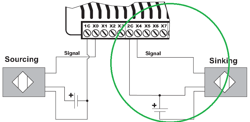
The input is wired up as a sinking (NPN) type configuration.
Configure the High Speed IO – BRX Do-More
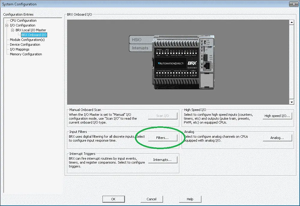
The first thing that we need to do is to configure our inputs and outputs. Go to the system configuration menu. This is located on the main menu | PLC | System Configuration… You can also click the icon on the main menu.
On the left-hand side of the system configuration menu, select BRX Do-More Onboard IO. This is located under I/O Configuration | BRX Local I/O Master | BRX Onboard I/O
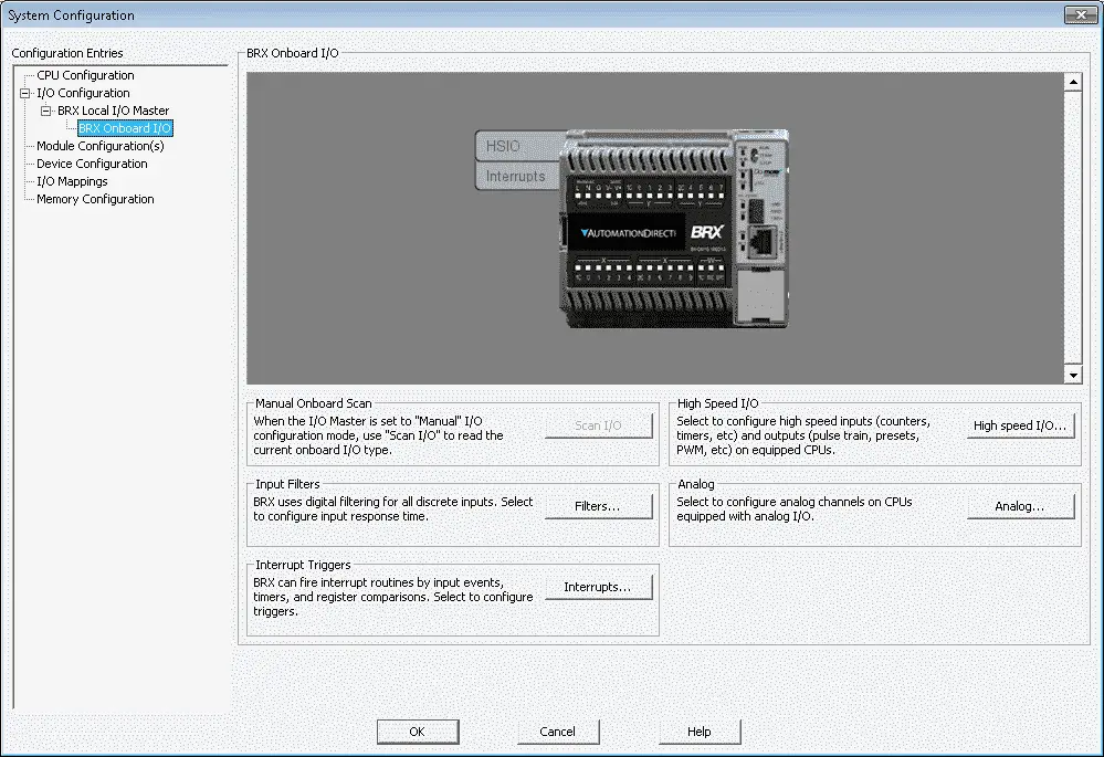
Input Filters
Select Input Filters from the BRX Onboard IO menu.
This will call up the filter table for the BRX CPU.
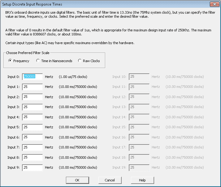
The default frequency for the inputs on the unit is 25Hz. This represents a speed of 25 counts per second that the PLC input can normally handle. This is much to slow for our output that we will be sending to the input location. Notice that we have changed input 0 to 250000 Hz. Inputs can be set as frequency, time in nanoseconds or raw clocks. I prefer to specify Hz, since most product specifications will be in this format.
Click OK to close this window and return to the BRX Onboard IO menu window.
High Speed IO… – BRX Do-More
We will now set up the high speed I/O.
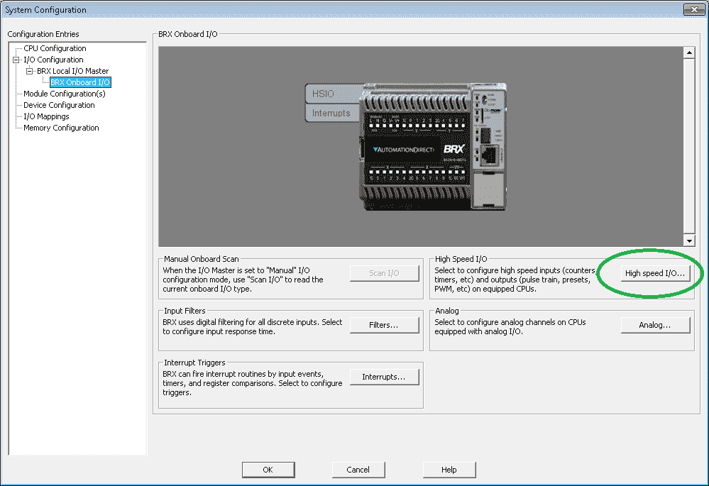
Select High speed I/O… from the menu.

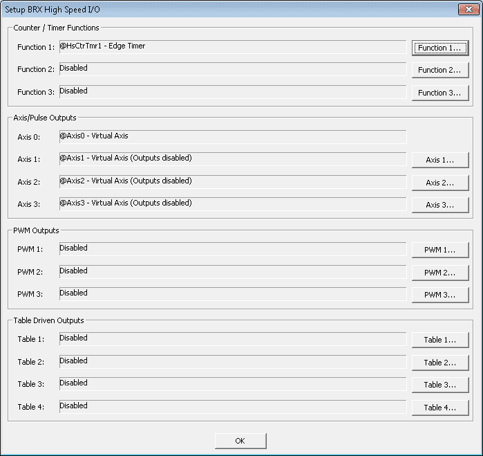
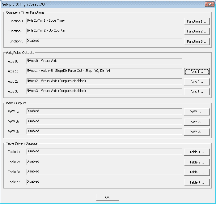
The Setup BRX Do-More High Speed I/O window will now be displayed. Under the Counter / Timer Functions, Select Function 1…
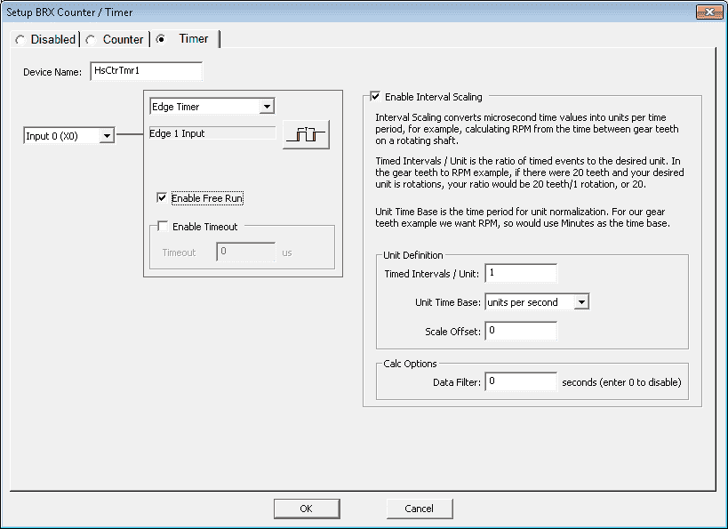
We will select the Timer function for the device. The name will be left as the default. (HsCtrTmr1) We will use an Edge Timer with input 0 (X0). The enable free run will be selected so we will only have to enable this timer once. (Continuous running) The register structure for the device will be automatically set up.
$HsCtrTmr1.EnableTimer – Enable Bit
$HsCtrTmr1.Acc – Current Time Value Register
$HsCtrTmr1.LastTime – Last Time Value Register
$HsCtrTmr1.TimerStarted – Started Bit
$HsCtrTmr1.TimerComplete – Completed Bit
Enable Interval Scaling is selected and is set for units per second. This is to show the frequency of the input using the $HsCtrTmr1.ScaledValue location.
Select OK to save our high speed timer device.
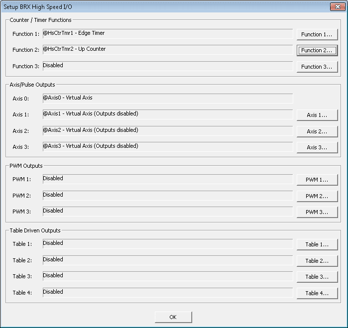
We can now see our device shown in our Counter / Timer Functions in our Setup BRX Do-More High Speed I/O window.
Select Function 2…
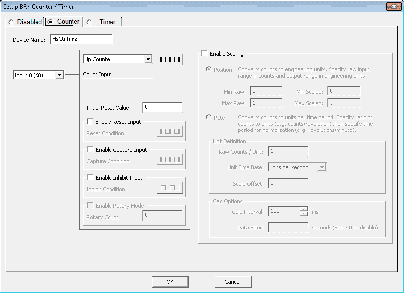
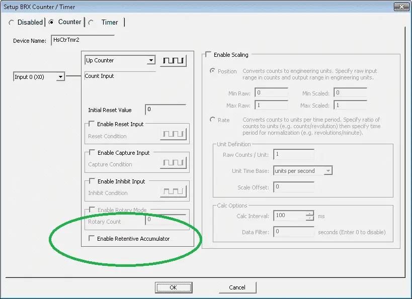
We will now set up the high speed counter. Select Counter from the tabs along the top of the window. We will leave the device name as the default. (HsCtrTmr2) The input will come from the Input 0 (X0) the same as above and this will be an Up Counter. We will leave everything else as default.
The register structure will be automatically set up for us again.
$HsCtrTmr2.Acc – Will contain the accumulated value of the counter.
Select OK.
Our high speed inputs are now set up for our application.
We will now set up our Axis 1… from the Setup BRX Do-More High Speed I/O window.
Select Axis 1…
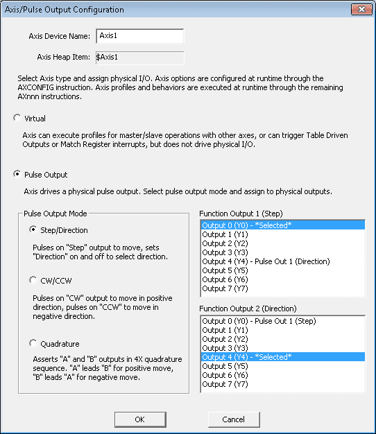
We will leave the default name of Axis1. This will again automatically set up the register structures (Heap) items.
Select Pulse Output with the mode of Step / Direction. Our pulses (steps) will be output 0 (Y0). The direction output will be Output 4 (Y4). We used this output so if we need another pulse outputs they will be available.
Select OK to save the configuration. The Axis options are configured at runtime through the AXCONFIG instruction. Operations are configured through the AX__ instructions.
Hit OK again to exit the Setup BRX High Speed I/O window menu.
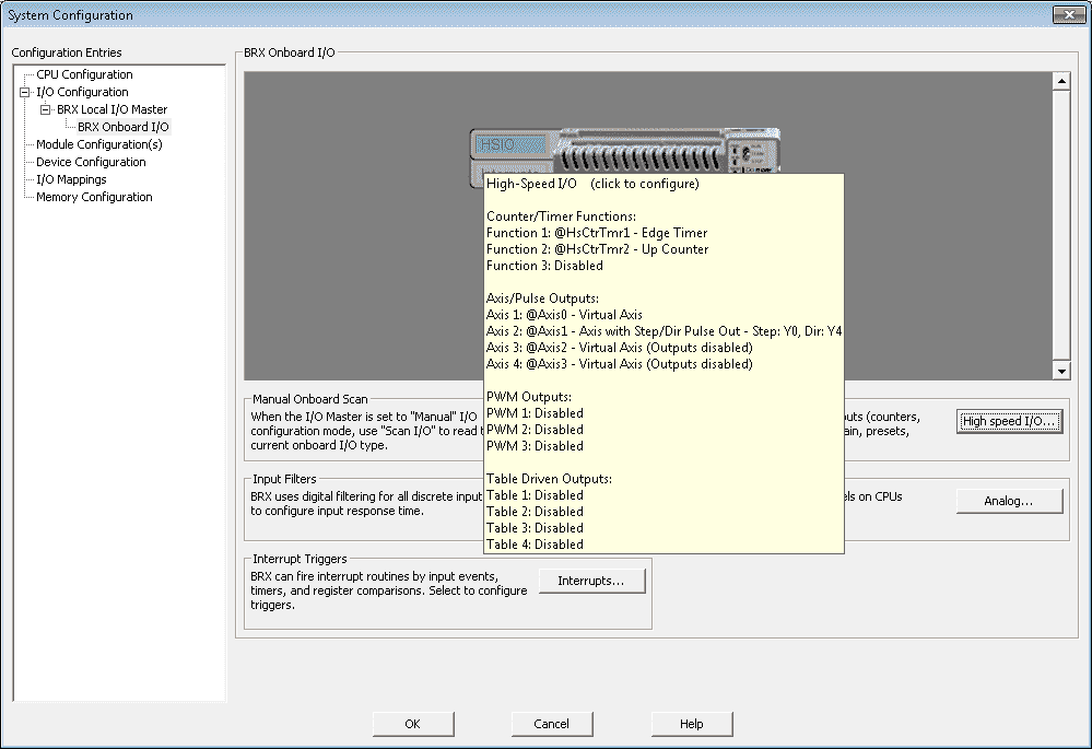
We can review our high speed IO settings by using the picture of the controller in the system configuration menu. Hover the mouse over the HSIO on the left hand side to see the instructions set in the controller.
We will now write the program to configure the Axis to give us the pulse output signals.
Instruction Flags
Do-More Designer uses differently coloured triangles in the upper left corner to show you how the instruction is used. All of the instructions that we will be discussing have a red (Fully Asynchronous) symbol.
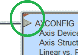
The fully asynchronous designates an instruction that is dependent on a device to complete the operation. This can be the hardware in the BRX Do-More Series PLC. When the instruction is executed, it will lock the device to get exclusive use. When the instruction is complete it will unlock the device.
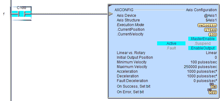
Axis Configuration
The first thing that we will do is set up our axis1 configuration.
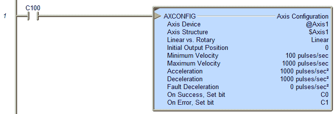
C100 will initialize our Axis1 device. We can then set up our parameters that we would like to see on the device.
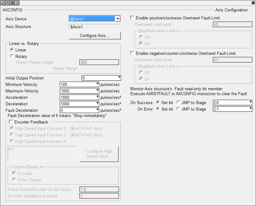
Our example will do a linear configuration with a minimum of 100 pulses per second. The maximum will be 250000 pulse per second. Acceleration / Deceleration can be left at the default of 1000 pulses second rate.
You will notice that we also have success and error bits. These are used to ensure that the Axis Device does not have errors when the instruction is being executed asynchronously.
We will use these bits as conditions for other instructions.
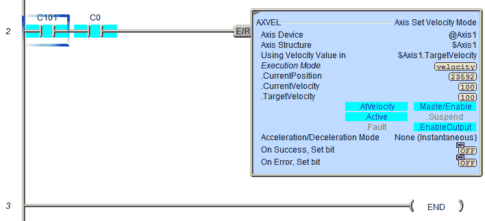
Axis Set Velocity Mode
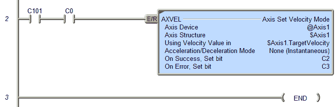
Our success bit from the Axis Configuration instruction and C101 will start our pulses being outputted from the BRX Do-More PLC.
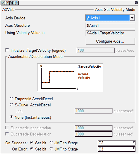
The instruction in our example is set up as instantaneous acceleration and deceleration. You could also use Trapezoid or S-Curve acceleration/deceleration. Our success and error bits are C2 and C3.
Testing our program – BRX Do-More High Speed IO
Call up the data view display. We can then set our bits to control our Axis1 device.
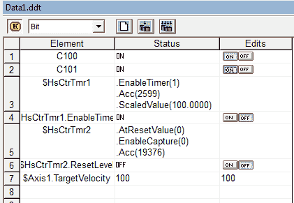
Note: $HsCtrTmr1.EnableTimer must be on for this device to work.
Setting new velocity values is easily done using the $Axis1.TargetVelocy register.
Status monitoring the program will show us the information in our instructions used.
You can watch the video below to see how the high speed inputs and outputs work in the BRX Do-More Series PLC.
You can download the program here.
We have just touched the surface of all of the features with the BRX Do-More High Speed IO and motion control. Please refer to chapter 12 of the operation manual for more ways in which you can utilize the high speed IO in your application. I have also included below the following links provided by Host Engineering on the capabilities of this controller’s HSIO.
The following are technical presentations on the BRX Do-More Series PLC – High Speed IO from Host Engineering:
HSIO – Counter / Timers – Host Engineering
Table Driven Outputs
Axis Pulse Outputs
BRX Do-More Series PLC from Automation Direct – Power to deliver
Overview Link (Configure and purchase a system)
Manuals and Product Inserts (Installation and Setup Instruction)
Do-More Designer Software v2.0.3 (Free Download Link) – The software will contain all of the instruction sets and help files for the BRX Series PLC.
Next time we will look at the compare instructions in the BRX PLC.
Watch on YouTube: BRX PLC High Speed IO
Note:
There has been an update to the BRX PLC. Do-More Update release 2.1.
BRX High Speed Counter has an added selection for Retentive Accumulator. (Non-retentive by default)
This release of the software has many new features like the ones above. You can download the newest version of the software free of charge here: http://support.automationdirect.com/products/domore.html
For additional updated features, please refer to the updates.pdf file in the installation folder.
If you have any questions or need further information please contact me.
Thank you,
Garry
If you’re like most of my readers, you’re committed to learning about technology. Numbering systems used in PLC’s are not difficult to learn and understand. We will walk through the numbering systems used in PLCs. This includes Bits, Decimal, Hexadecimal, ASCII and Floating Point.
To get this free article, subscribe to my free email newsletter.
Use the information to inform other people how numbering systems work. Sign up now.

The ‘Robust Data Logging for Free’ eBook is also available as a free download. The link is included when you subscribe to ACC Automation.