PLC manufactures have their own proprietary protocols. These methods of communication will allow you to program the controller. Other protocols will allow you to collect and log information from the programmable logic controller. Node-RED has the ability to read and write to the Omron controller using special protocol commands.
We will connect Node-RED to the Omron CP1H PLC. A serial RS485 interface will be used for communication to the industrial controller. We will demonstrate reading and writing using Host Link (C-mode commands) to the Omron PLC. Let’s get started.
In this series we used Node-RED in some of the following ways:
Installing the Windows Software – Video
Modbus Communication – Video
User Interface – Dashboards – Video
SQL Database Log – Video
SQL Database Spreadsheet Connection – Video
Install Node-RED on Raspberry Pi – Video
Do-More PLC Node-RED HTTP Request – Video
Simple Click Data Logging – Video
Node-RED Modbus TCP Handling Errors –Video
Raspberry Pi Serial Port Programming – Video
Omron C-mode (Host Link)
C-mode commands are specialized Host Link communications commands.
They are issued by a host computer and sent to a CPU Unit. The devices that can be connected for serial communications are the CPU Unit, a Serial Communications Unit, and a Serial Communications Board.
C-mode (Host Link) commands form a command/response system for serial communications (Host Link Mode) to perform various control operations between a CPU Unit and a host computer directly connected to it. These operations include reading from and writing to I/O memory, changing operating modes, executing forced set and forced reset operations, and so on.
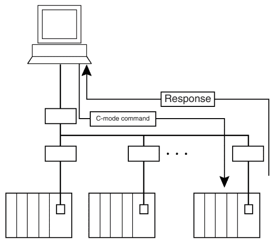
There are two Host Link formats: the 1:N Host Link (with N ≥ 1) and the 1:1
Host Link. We will be using the 1:N since RS485 will be used. (This is the most common setting.) Up to 32 PLCs (Host Link Units) can be connected to a single host computer. For identification, each Host Link Unit is assigned a unit number from 0 to 31.
Omron C-mode (Host Link) Command/Response Formats
C-mode Host Link uses a command response format for the communication. This means that the slave units will only respond when the master gives a command. So they will only reply if the message is directed to them.
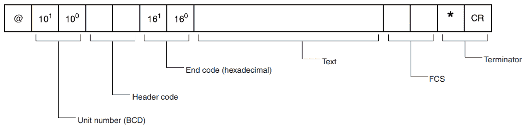
The command frame looks like this:
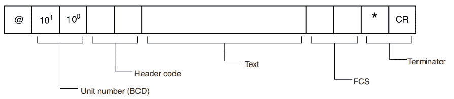
• @: Must be attached at the beginning of the command.
• Unit number: Set in BCD from 0 to 31 for each Host Link Unit.
• Header code: Specified in two characters.
• Text: Set parameters corresponding to command code.
• FCS: Calculate 2-character FCS (frame check sequence) at host
computer. For details on calculating FCS, refer to FCS Calculations later in this section.
• Terminator: Set “*” and CR (CHR$(13)) as two characters to indicate
the end of the command.
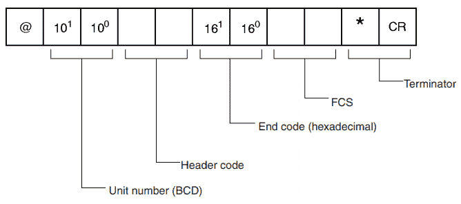
The response frame will look like this:
• @: Must be attached at the beginning of the response.
• Unit number: Set in BCD from 0 to 31 for each Host Link Unit.
• Header code: The command code that was received is returned.
• End code: The results (error status, etc.) of command execution are
returned.
• Text: Returned only if there is read data.
• FCS: The 2-character FCS (frame check sequence) is returned.
• Terminator: Two characters indicating the end of the command, “*” and
CR (CHR$(13)), are returned.
If an error occurs, then the response frame will look like this:
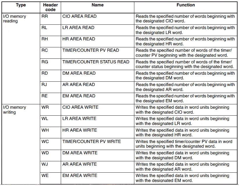
Omron C-mode (Host Link) Command Codes
Here is a partial list of the commands that can be used to get or set information in the Omron controller.
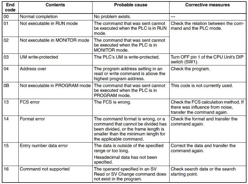
Here are the response (end) codes that are returned in the response frame. When two or more errors occur, the end code for the first error only will be returned.
All of the commands and responses for the Omron C-mode (Host Link) and FINS Ethernet protocol can be found in this manual.
Watch the video below to see this protocol in action on our CP1H PLC controller.
CP1W-CIF11 RS-422A/485 Option Boards
An RS-422A/485 Option Board is mounted to an Option Board slot on the CP1H CPU Unit.
Pic_png
Here are the components of this communication option board.
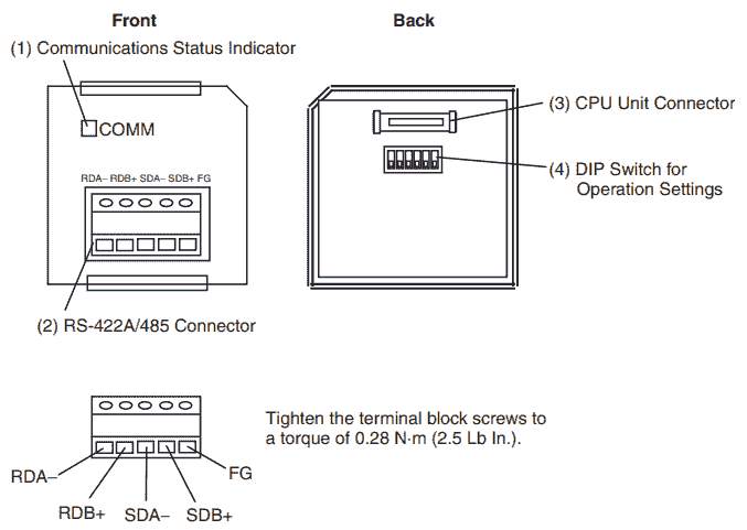
The dip switches will determine how this board will operate.
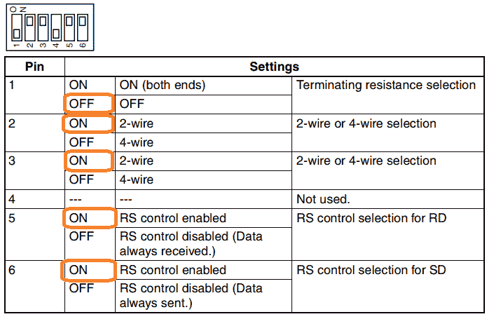
We will set this up for 2-wire RS485. RS control will be enabled so we will not receive any echo.
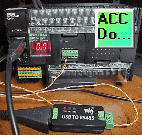
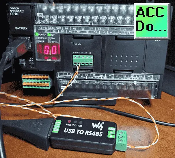
Waveshare USB to RS485 Converter
We will be using an industrial USB to RS485 converter on our computer. The Waveshare USB to serial port is a 2-wire USB to RS-485 serial communication adapter for RS485 use. It does not require an external power supply or complicated configuration.
Installation of the Waveshare USB to Serial PC Converter can be seen here.
The wiring will be a twisted pair between this converter and the communication option board on the PLC. A+ will be wired to RB+ and B- will be wired to RB-.
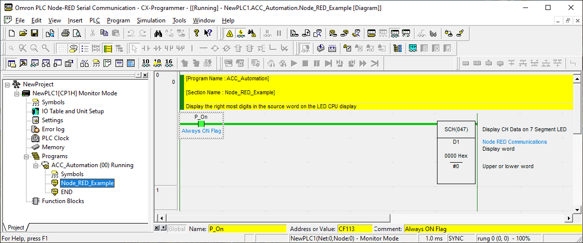
Omron CP1H Program
Our program will be very simple. We will control the LED display digits on the CP1H CPU unit with data memory 1. (D1)
When writing to an Omron PLC we must ensure that the PLC is in monitor mode. This is done through the settings of the PLC.
Main menu | PLC | Edit | Settings
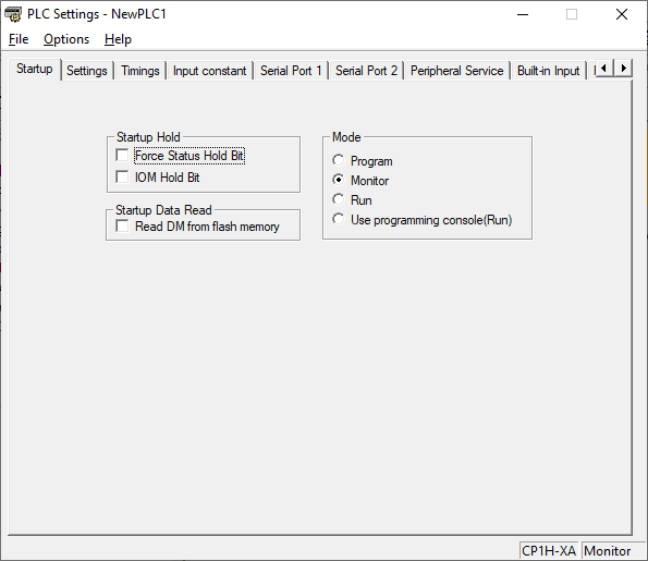
Under the startup tab at the top of the window, change the mode to monitor. Select the serial port 1 tab.
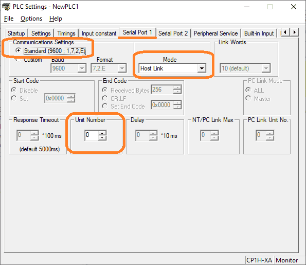
We will be leaving all of these settings as their default. Make a note of the communication parameters so we can ensure these match our Node-RED program.
Communication Settings:
Standard – 9600 baud, 1 start bit, 7 data bits, 2 stop bits, even parity
Host Link Mode
Unit number of the device – 0
Save and download the program to the Omron CP1H industrial controller. The entire Omron CP1H controller series can be found here. This includes hardware and software instructions for this controller.
Node-RED Program Nodes Required
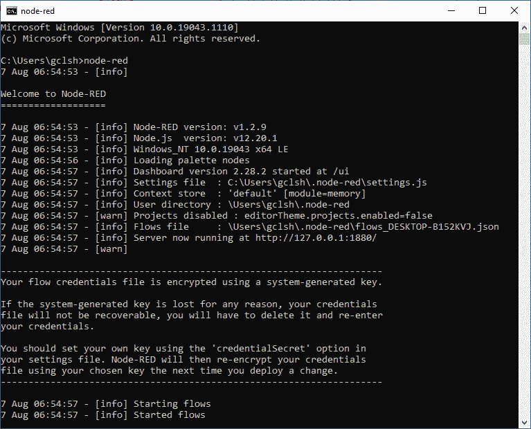
We will be running node-red on a windows 10 computer.
The entire Node-RED series can be found here. This will show you how to install and use this IoT enabling software.
Using the manage palette we can add the two new modules that we will need for the Omron serial communication.
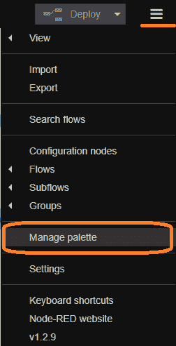
Select manage palette.
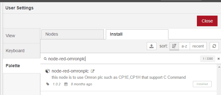
Install the node-red-omronplc module.
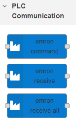
This will install the above three nodes.
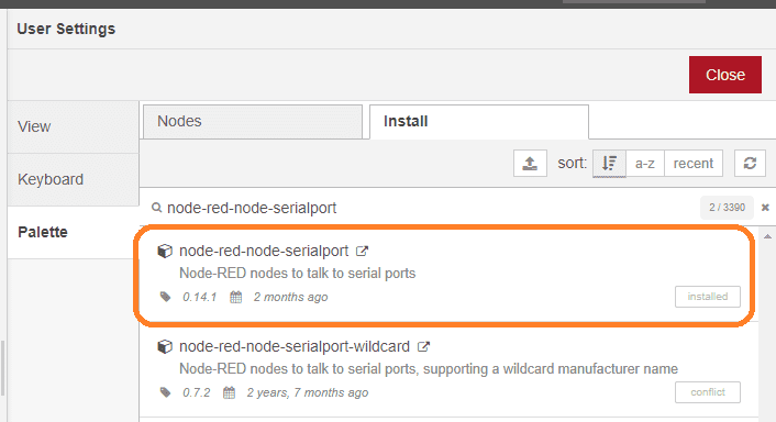
Install the node-red-node-serialport module.
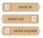
The serial nodes will be installed.
Node-RED Omron Serial Read Flow
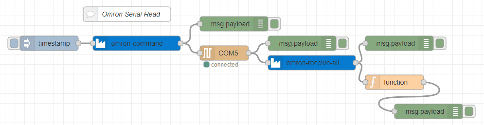
The inject node is used to initiate the flow to read information from the Omron industrial controller.
The Omron command node is used to specify the c-code (Host Link) command that we want for our reading.
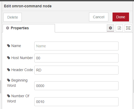
The host number is set for 00. This is the same as what was set above on our communication module for the CP1H controller.
Our header code is RD. This is to read the Data Memory area of the PLC.
The beginning word will be 0000 and the number of words will be 0010. This means that we are requesting D0 to D9 memory areas to be read.
Message payloads are used along the way to show the current information. This is a great way to test or troubleshoot your Node-RED flow program.
Here is the output of the omron-command node: @00RD0000001057*
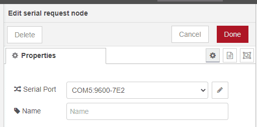
The serial request node is used because we want to send and receive information from the serial port. In our case, we are using communication port 5, 9600 baud, 7 data bits, even parity, and 2 stop bits. The 1 start bit is understood to be a default. This matches the default settings from above. Select the edit icon on the serial port line to modify or review the port settings.
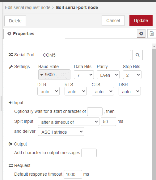
In our example, we are waiting for a timeout of 50 milliseconds to ensure that all of the characters have been received.
Here is the input of the serial request node: @00RD0011970000000600014321678922220000000000005B*
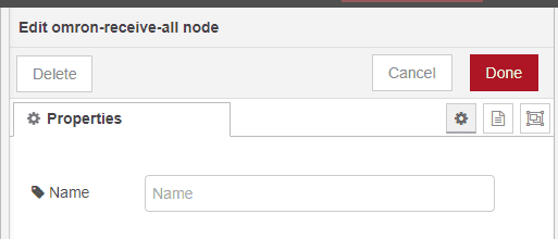
The Omron receive all and Omron receive nodes are used to strip off the header, FCS, and termination ASCII characters. The output is a single string with the information requested.
The output would now look like this: 1197000000060001432167892222000000000000
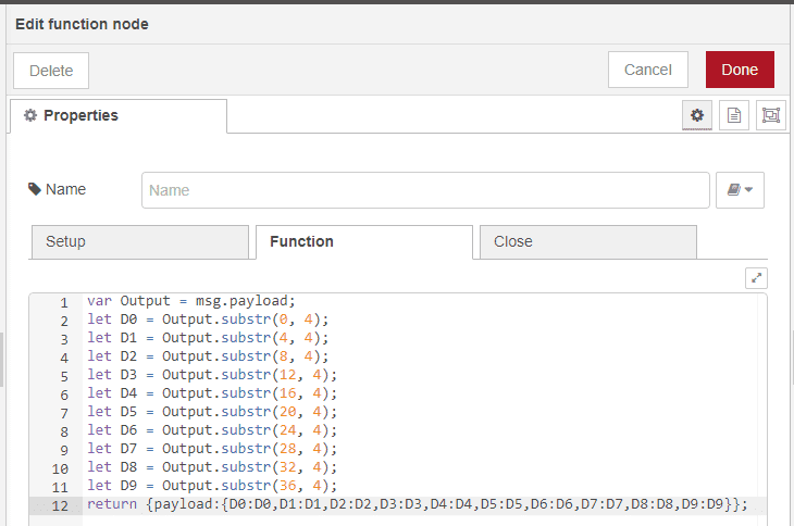
The function node is used to take the response string and turn this into an array.
We can then use this information to save to a database, display on a dashboard, or use it anywhere else in our flow.
The array output will look like this: {“D0″:”1197″,”D1″:”0000″,”D2″:”0006″,”D3″:”0001″,”D4″:”4321″,”D5″:”6789″,”D6″:”2222″,”D7″:”0000″,”D8″:”0000″,”D9″:”0000”}
Watch the video below to see the operation of this flow to read serial data from the Omron PLC.
Node-RED Omron Serial Write Flow
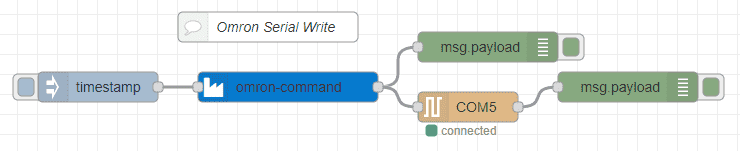
The Omron command node is used once again to specify the c-code (Host Link) command that we want. In this case, we will use it for writing to our Omron PLC.
Note: The Omron PLC must be in monitor mode in order to write to the industrial controller.
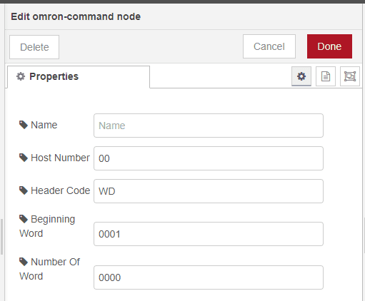
The header code would be WD. This means that we are writing to the data memory area of the PLC. The beginning word is 0001 and the number of words is 0000. This means that 0000 will be written to D1. In our case, our PLC program will display the right to digits on the LED display of the controller.
Note:
The beginning word must be 4 digits in length.
The number of words must be in multiples of 4 digits. Example: 00001234 – This will write 0000 in the first memory register and 1234 in the next memory register.
The output of the omron-command node will be: @00WD0001000052*
The input of the serial request node will be: @00WD0053*
Watch the video below to see this flow in operation.
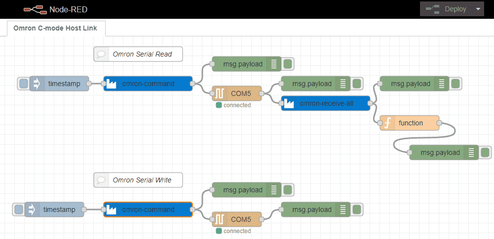
This is our complete Node-Red program.
Download the PLC and Node-RED programs here.
Watch the video below to see the serial communications using Node-RED on our windows computer to an Omron CP1H PLC.
Node-RED Links
Node-RED Organization Home Page
Getting Started – Run Locally
Node-RED running on Windows (Run at Startup)
Securing Node-RED
Node-RED Essentials Videos (Basics of the Editor)
Learn JavaScript Free
w3schools JavaScript Tutorial
learn-js.org
Node-Red JavaScript Primer
Modbus
Node-RED Modbus TCP and Serial
Dashboard – HMI
Node-RED Dashboard
Node-RED Dashboard extra nodes
SQL Database
Node-RED SQL Database
Node-RED SQL Plus – Execute queries and stored procedures
Modbus Learning Links:
Simply Modbus Frequently Asked Questions
Modbus TCP/IP Overview – Real-Time Automation
All You Need to Know About Modbus RTU – Video
Watch on YouTube: Omron PLC Node-RED Serial Communication
If you have any questions or need further information please contact me.
Thank you,
Garry
If you’re like most of my readers, you’re committed to learning about technology. Numbering systems used in PLCs are not difficult to learn and understand. We will walk through the numbering systems used in PLCs. This includes Bits, Decimal, Hexadecimal, ASCII, and Floating Point. To get this free article, subscribe to my free email newsletter.
Use the information to inform other people how numbering systems work. Sign up now. The ‘Robust Data Logging for Free’ eBook is also available as a free download. The link is included when you subscribe to ACC Automation.