We will connect the Productivity Mini PLC P1-M622-16DR to our computer running the Productivity Suite Software. An Ethernet (RJ45) communication link will be made to our programmable logic controller.
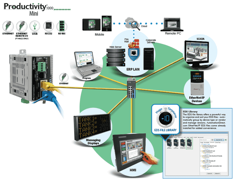
The P1-M622 series packs six communication ports into a standalone package smaller than your hand. That’s USB-C programming, dual Ethernet ports, RS-232, RS-485, and a microSD slot for data logging—all without needing separate I/O modules or power supplies.
Let’s get started.
Previously in this Productivity Mini PLC series, we have discussed:
P1-M622-16DR Mini PLC System Hardware – Video
Installing the Software – Video
Establishing Communication – Video
First Program – Video
Monitoring and Testing the Program – Video
Wiring and Testing – Video
Online Editing and Fail-Safe Wiring – Video
P1-M622-16DR Communication Ports:
The P1-M622-16DR Mini PLC includes the following communication ports:
| Item | Communication Port |
|---|---|
| 1 | microSD Slot |
| 2 | USB-C 2.0 Programming Port |
| 3 | RS-232 Serial Port (RJ12) |
| 4 | RS-485 Serial Port (TB Style) |
| 5 | 10/100 MB Ethernet Port |
| 6 | 10/100 MB Ethernet Port, Remote I/O |
Note: The USB-C port is NOT compatible with older 1.0/1.1 full-speed USB devices.
Mini PLC Connection:
Connect our RJ45 Ethernet cable from the Ethernet port on the Productivity Mini PLC P1-M622-16DR to our network router or switch. Our computer is also connected to the router or switch on the same network.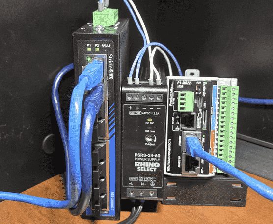
Start the Productivity Suite software package. Double click on the shortcut icon on your screen or from the Windows start button (All Programs | AutomationDirect | Productivity Suite | Productivity Suite)
Call the Productivity CPU Connections Window
When you first start up the Productivity Suite software, you will get the start menu.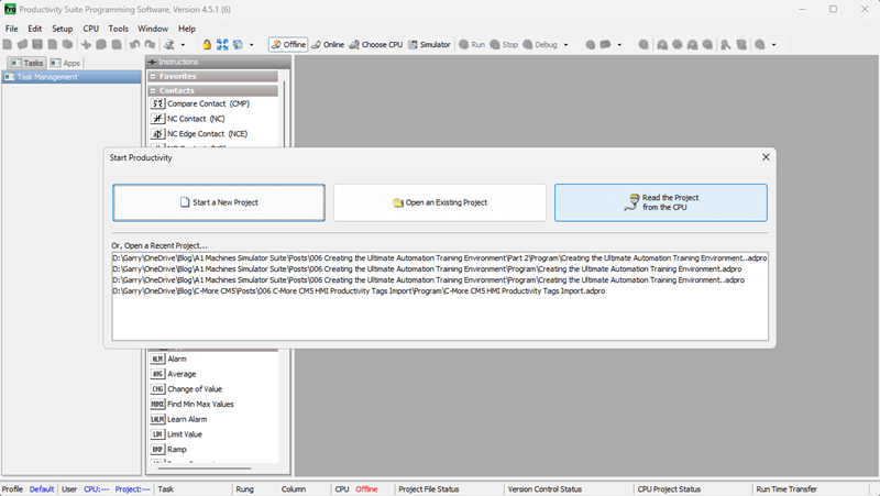
Click on “Read the Project from the CPU”
This will call up the CPU connections window.
You can also get to this window at anytime by one of the following three ways:
- Click the “Choose CPU” icon in the software’s main menu.
- Click “Choose CPU” from the Application Tools menu under Control CPU.
- Click “Choose CPU” from the main menu under CPU.
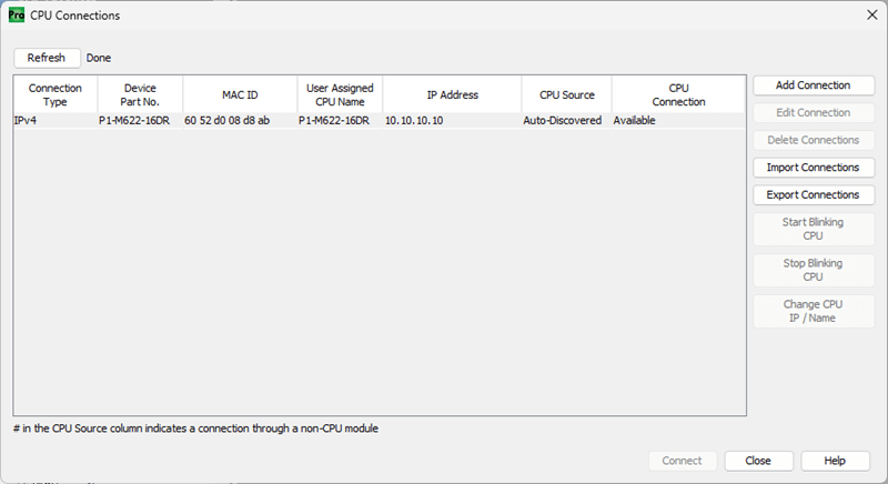
Click the IPv4 connection in the CPU Connections window. You will notice we now have some additional choices that we can change.
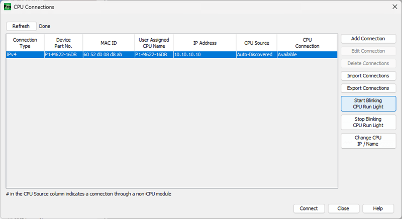
Click “Start Blinking CPU Run Light”. This will start the run light on the P1-M622-16DR unit blinking. It is a great way to ensure that we are communicating with the correct PLC unit.
Click “Stop Blinking CPU Run Light”. The run light will stop blinking.
Change IP Address (Productivity Ethernet Communication)
Highlight the Ethernet connection type in our CPU connections window.
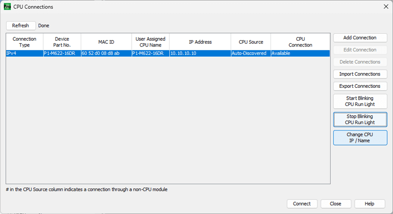
Click “Change CPU IP / Name”
The Change IP Address / CPU Name window will now appear.
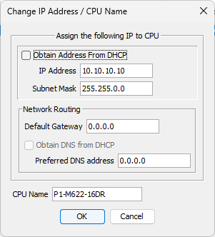
Ensure that the Ethernet Port is selected. We will now change the settings to the following:
- IP Address: 192.168.1.156
- Subnet Mask: 255.255.255.0
- Default Gateway: 192.168.1.1 (Access to the Internet)
See the following for a review of IP addressing:
https://accautomation.ca/what-everybody-ought-to-know-about-ip-addressing/
The CPU Name default is the model number (P1-M622-16DR). We will leave this as is, but you could change the name to something easier to address in your automation project.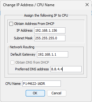
Click “OK” to save the changes made.
Notice that the IP address has changed in our CPU Connections window.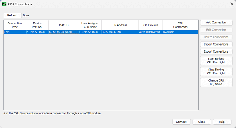
Connect to the PLC – Establishing Ethernet Communication
Click on the Connect button. This will select the Ethernet port we want to use for programming the unit in our CPU connections window.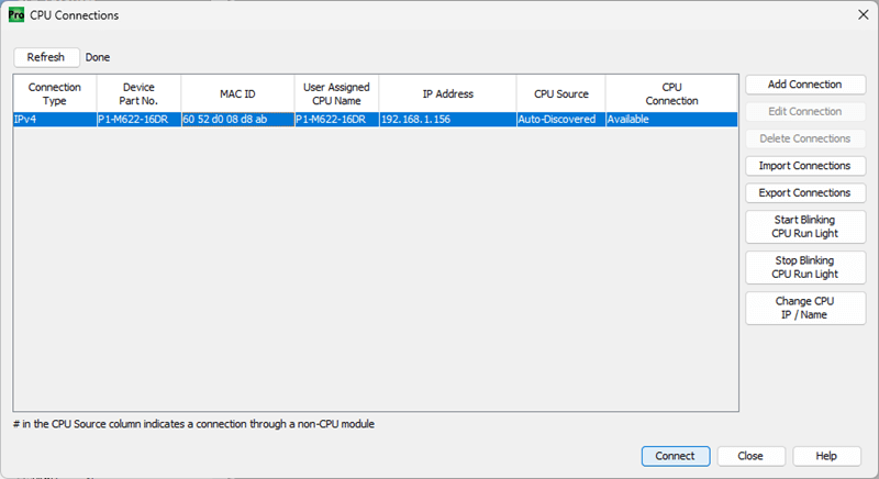
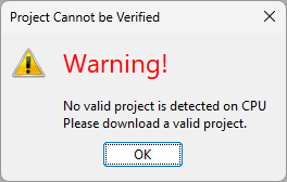
We currently have no project in our CPU, so a warning message is shown. Click OK.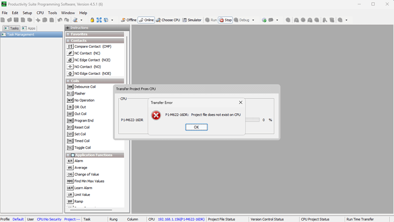
Our screen will now show that we are connected, the PLC’s current mode, and the PLC’s connection status.
The icon in the software’s main menu shows we are Online and in Stop mode.
The Application Tools menu under Control CPU also shows that we are Online and in Stop mode.
The status bar at the bottom of the screen, under CPU, will show our connection type and the CPU name.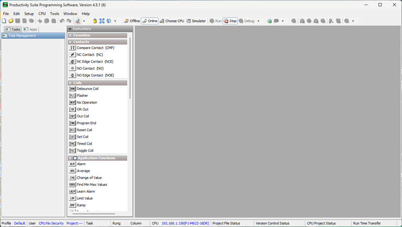
CPU (Ethernet Connection) 192.168.1.156 – Name P1-M622-16DR
Establishing communication with our Mini PLC is straightforward. You can watch the video below for a demonstration on establishing communication from Productivity Suite to the P1-M622-16DR Mini PLC.
P1-M622-16DR Communication Capabilities
The Mini PLC Ethernet port supports:
- Modbus TCP Client connections (16 server devices)
- Modbus TCP Server connections (16 client devices)
- EtherNet/IP Scanner (32 Adapters)
- EtherNet/IP Adapter (4 scanners with 8 connections per device)
- Custom Protocol over Ethernet (CPoE)
- ProNET for Productivity-to-Productivity communication
- Outgoing Email
The Remote I/O Ethernet Port supports:
- GS Drive connections (up to 16 drives)
- ProtosX TCP couplers (up to 4)
- P1-RX remote slave modules (up to 4)
- PS-AMC motion controllers
The Serial Ports support:
- RS-232: Modbus RTU Master/Slave, ASCII, Custom Protocol
- RS-485: Multi-drop Modbus RTU networks (up to 1000 meters), ASCII communication
Productivity Mini PLC P1-M622-16DR from AutomationDirect
Overview Link (Additional Information on the Unit)
Configuration (Configure and purchase a system – BOM)
User Manual and Inserts (Installation and Setup Guides)
Productivity Suite Programming Software (Free Download Link)
This software includes all instruction sets and help files for the Productivity Series.
Next time, we will write our first program and transfer it to the Productivity Mini PLC P1-M622-16DR.
The Productivity Mini PLC series from AutomationDirect, and specifically, the P1-M622-16DR, is a compact powerhouse that packs serious capability into a surprisingly small footprint. To learn more, click here. Click here to build digital twins of 3D virtual machinery, test control logic, and learn automation without expensive hardware, using Machine Simulator.
Watch on YouTube: P1-M622-16DR Mini PLC Establishing Communication!
If you have any questions or need further information, please contact me. Garry
Related Posts:
- How to Install Productivity Suite PLC Programming Software FREE
- Productivity 1000 PLC Establishing Communication
- What Everybody Ought to Know About IP Addressing
There are many different PLC manufacturers with other hardware and software. All of the programmable logic controllers have similar basic features. Here is how I would approach learning about basic PLCs.
Once you are familiar with the basics of the PLC, you will then learn specifics for the controller you will be programming.
This is the easiest way to learn about PLC programming.
Here are the controllers that we have covered or are covering at ACC Automation:
LS Electric XGB PLC Series
BRX Do-More Series (Do-More Designer Software + Simulator)
Productivity Series P1000 / P2000
Click PLC Series
Omron CP1H Series
Horner XL4 PLC Series
Arduino Opta PLC
The EasyPLC Software Suite is a comprehensive package that includes PLC, HMI, and machine simulator software. This allows you to make a digital twin. See below to receive 10% off this software. This PLC learning package contains the following:
Easy PLC – PLC Simulation will allow programming in Ladder, Grafcet, Logic Blocks, or Script.
HMI System – Easily create a visual human-machine interface (HMI)
Machine Simulator – A virtual 3D world with real-time graphics and physical properties. PLC programs can be tested using the EasyPLC or through other interfaces. (Modbus RTU, TCP, etc.)
Machine Simulator Lite – Designed to run on Android Devices.
Machine Simulator VR – Virtual Reality comes to life so you can test, train, or practice your PLC programming.
Purchase your copy of this learning digital twin package for less than $95 USD for a single computer installation or less than $110 USD to allow access on multiple computers.
Receive 10% off the investment by typing in ACC in the comment section when you order.
Learn PLC programming the easy way. Invest in yourself today.
Examples of PLC program development using the five steps.
Click PLC – Easy Transfer Line Programming – Video
Productivity PLC Simulator – Chain Conveyor MS – Video
Five Steps to PLC Program Development – Die Stamping
PLC Programming Example – Process Mixer
PLC Programming Example – Shift Register (Conveyor Reject)
PLC Programming Example – Paint Spraying
PLC Programming Example – Delay Starting of 7 Motors
PLC Programming Example – Pick and Place
PLC Programming Example – Sorting Station (Shift Register)
PLC Programming Example – Palletizer
If you’re like most of my readers, you’re committed to learning about technology. The numbering systems used in PLCs are not difficult to understand. We will walk through the numbering systems used in PLCs. This includes Bits, Decimals, Hexadecimal, ASCII, and Floating Points.
To get this free article, subscribe to my free email newsletter.
Use the information to educate others on how numbering systems work. Sign up now.

The ‘Robust Data Logging for Free’ eBook is also available as a free download. The link is included when you subscribe to ACC Automation.