One of the most powerful features of the Productivity Suite software is the built-in PLC simulator. If you don’t have the physical P1-M622-16DR hardware yet—or you’re developing logic at your desk before heading to the plant floor—the simulator lets you program, modify, and test your ladder logic without a single piece of hardware connected. This is a game-changer for learning, development, and troubleshooting.
We will now use the start-stop motor circuit we have already built in this series to walk through the simulator step by step. You’ll see how easy it is to run your program virtually, toggle inputs in real time, and verify your logic is working correctly before you ever touch the physical hardware.
Let’s get started.
Previously in this Productivity Mini PLC P1-M622-16DR series, we have discussed:
P1-M622-16DR Mini PLC System Hardware – Video
Installing the Software – Video
Establishing Communication – Video
First Program – Video
Monitoring and Testing the Program – Video
Wiring and Testing – Video
Online Editing and Fail-Safe Wiring – Video
What is the Productivity Suite Simulator?
The Productivity Suite simulator is a built-in software feature that emulates the behavior of a real Productivity Series CPU directly on your computer. Think of it as invisible hardware sitting on your desk. The simulator accepts your ladder logic program the same way a physical PLC does—you transfer the project to it, put it in Run mode, and your program starts executing.
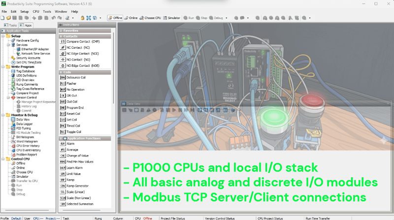
The simulator supports the full P1000, P2000, and P3000 CPU families, including:
- P1000 CPUs and local I/O stack
- All basic analog and discrete I/O modules
- Modbus TCP Server/Client connections on your computer’s Ethernet port
You will need Productivity Suite version 3.8.x.x or higher. If you followed along with our software installation post in this series, you are already set. The software is a free download from AutomationDirect—no license or additional purchase required.
Simulator Capabilities:
- Analog and discrete I/O simulation
- Full Data View monitoring
- Modbus TCP/IP Client or Server connections (great for testing HMI communication)
- Ladder logic monitoring in real time
Current Simulator Limitations to Be Aware Of:
- No intelligent modules
- RS-232/485 ports are not simulated
- PID instructions are not supported
- Motion instructions are not supported
- The simulator will time out after 2 hours—plan your sessions accordingly
For our start-stop motor circuit, none of these limitations apply. All we need is discrete I/O, and the simulator handles that perfectly.
Opening Our Existing Project
We will use the start-stop motor circuit that we created earlier in this series. If you saved your project file, open it now in the Productivity Suite software.
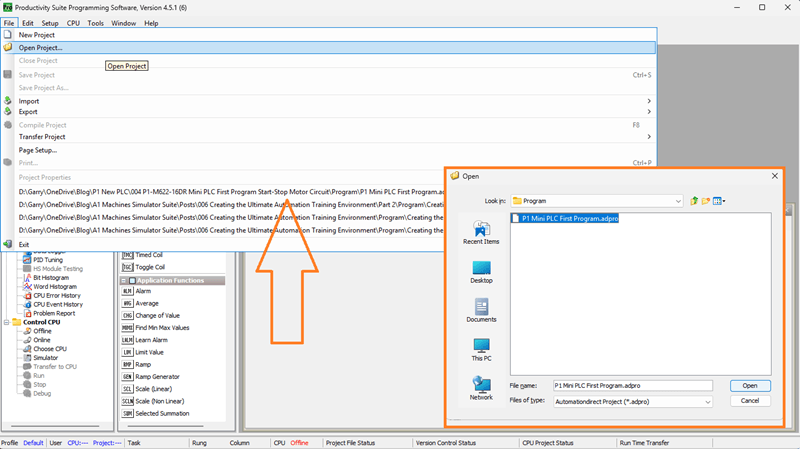
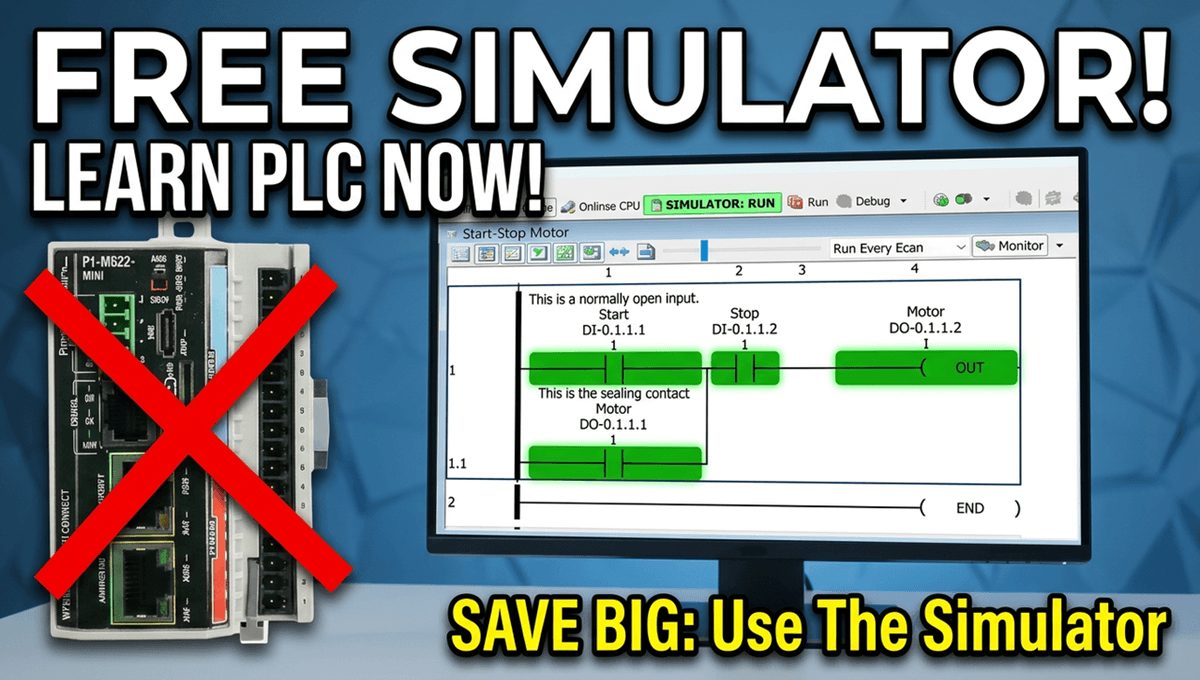
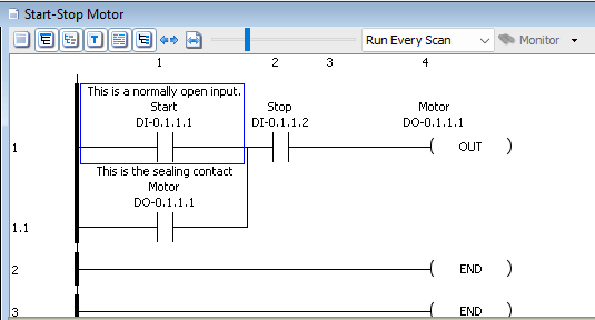
You should see our familiar ladder logic with:
- DI-0.1.1.1 – Start (Normally Open contact in ladder)
- DI-0.1.1.2 – Stop (Normally Closed contact in ladder)
- DO-0.1.1.1 – Motor output coil with sealing contact
If you don’t have the saved project, you can quickly rebuild it—the First Program post in this series walks through every step.
Before starting the simulator, let’s set up our Data View so we have a good monitoring panel ready to go.
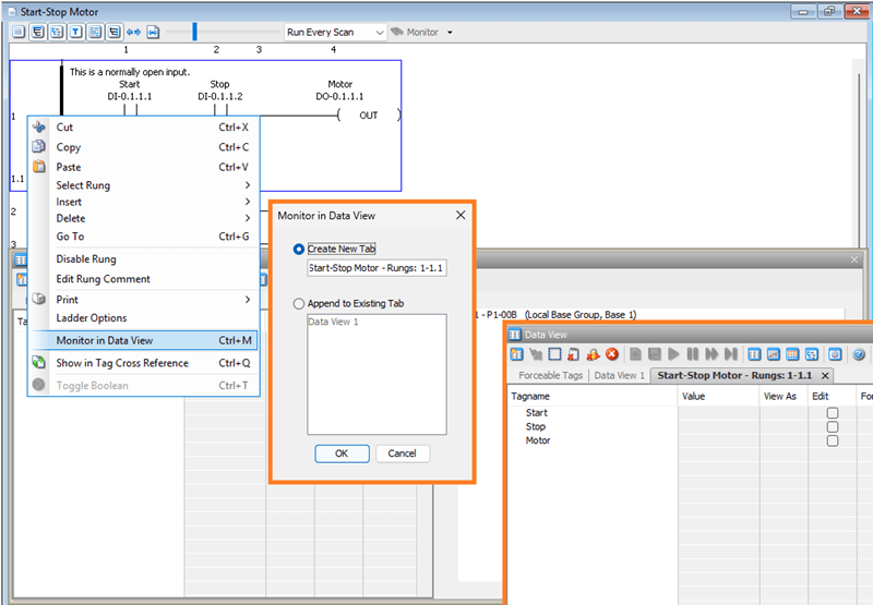
Right-click on the rung in the ladder editor and select Monitor in Data View. Leave the selection as Create a new tab and click OK. This will populate the Data View tab with all the tags from our rung—Start, Stop, and Motor —automatically. Having this ready before launching the simulator will save time once the program is running.
Starting the Simulator
With the project open and Data View set up, we are ready to launch the simulator.
There are two ways to do this:
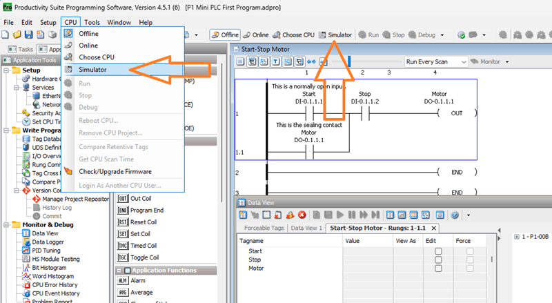
- Select the Simulator icon on the main toolbar
- Use the main menu: CPU | Simulator
A warning message will appear.
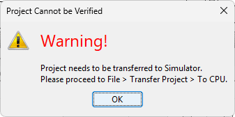
This is simply telling you that the program needs to be transferred to the simulator before it can run—exactly the same process as connecting to physical hardware. Select OK.
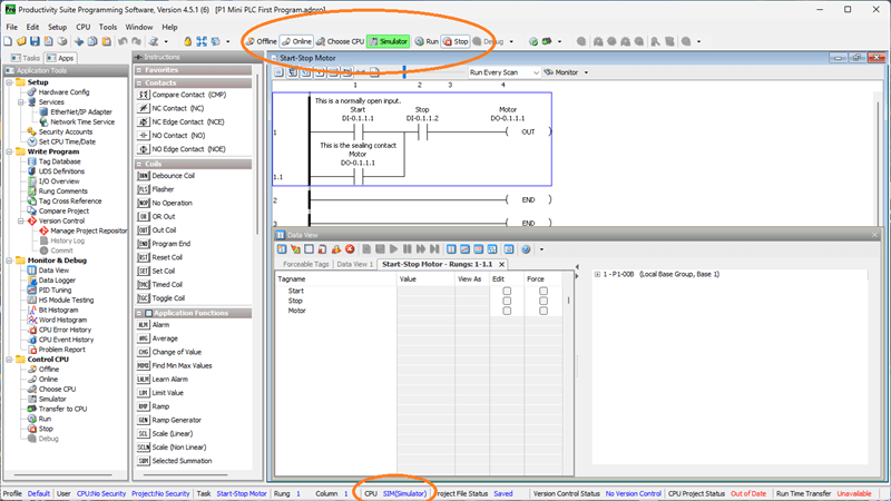
You will notice the status bar at the bottom of the screen now shows that you are online with the PLC Simulator (SIM). The toolbar icons will reflect an online connection.
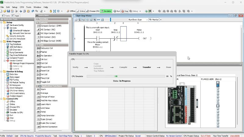
Transferring the Program to the Simulator
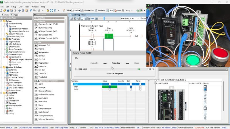
Just like a real PLC, the simulator needs the program transferred to it before it can run. Select the Transfer Project to CPU icon on the toolbar, or use the main menu: File | Transfer Project | To CPU.
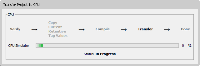
The transfer dialog will appear and the program will download to the simulator. This is the same process you would follow with the physical P1-M622-16DR connected over USB-C or Ethernet—a great habit to build.
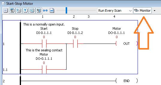
Once the transfer is complete, click on the ladder logic window and select Monitor to enable live ladder monitoring.
Putting the Simulator in Run Mode
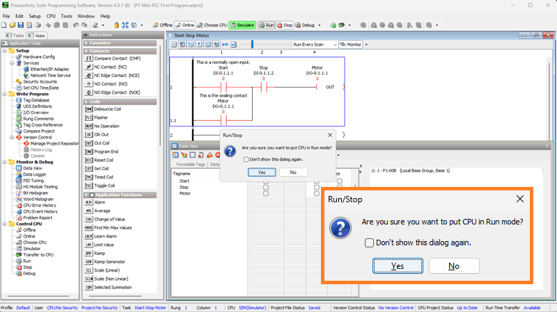
Now select the Run icon on the toolbar, or go to CPU | Run. A confirmation window will appear asking if you want to place the PLC simulator into Run mode. Click Yes.
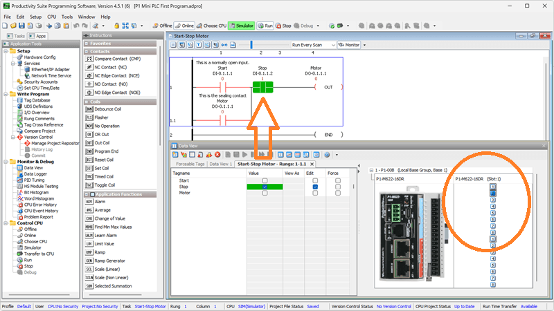
Your ladder logic is now executing in the simulator. Watch the ladder editor—you will see the contacts and coils display their current states just as they would with real hardware connected. With the default display mode showing green (ON) and red (OFF), everything is reading correctly:
- Start contact (DI-0.1.1.1) – OFF (red)
- Stop contact (DI-0.1.1.2) – OFF (red, because it is a Normally Oprn contact in our ladder)
- Motor output coil (DO-0.1.1.1) – OFF (red)
This is exactly what we would expect. No inputs are active, so the motor is off.
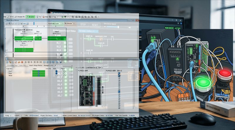
Controlling Inputs Through the IO View
This is where the simulator really shines. We can toggle inputs on and off directly in the software to simulate pressing physical buttons. Open the Data View panel if it isn’t already visible: Tools | Data View or the shortcut Ctrl + Shift + F3.
In the Data View window, click the Toggle IO View icon. Then click the + symbol to expand the IO View panel. You will now see a graphical representation of the P1-M622-16DR’s I/O in the simulator—8 discrete inputs and 8 relay outputs laid out just like the real module.
Simulating the Stop Button: Click on Input 2 (DI-0.1.1.2) in the IO View. This simulates not pressing the Stop button. (Wired normally closed.)
Simulating the Start Button: Click on Input 1 (DI-0.1.1.1) in the IO View. This simulates pressing the Start button.
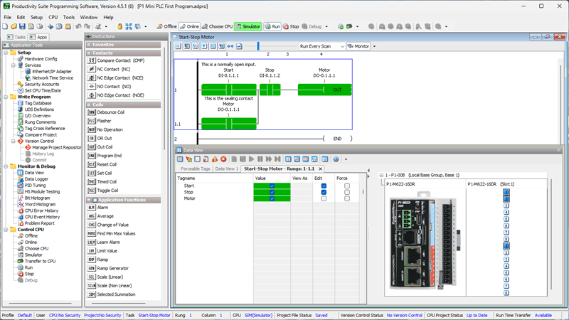
Watch the ladder logic window:
- The Start contact turns green (ON)
- The Motor output coil energizes (turns green)
- The sealing contact (DO-0.1.1.1 in the second branch) also turns green, latching the circuit
Now click Input 1 again to release it—simulating letting go of the Start button.
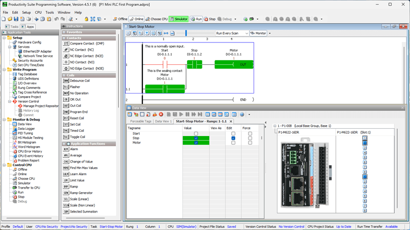
The motor output remains ON. The sealing contact is doing its job, holding the circuit energized exactly as it would in the real wiring scenario. This is the core behavior of a start-stop motor circuit, and we have just verified it without a single wire connected.
Simulating the Stop Button: Click on Input 2 (DI-0.1.1.2) in the IO View. This simulates pressing the Stop button.
Because the Stop contact on our ladder is Normally Open (NO), energizing Input 2 opens the contact and breaks the rung. Watch the ladder logic:
- The Stop NO contact opens (turns red)
- The Motor output coil de-energizes (turns red)
- The sealing contact drops out
Click Input 2 again to release the Stop button. The circuit is now back in its normal state—ready to start again. The motor remains off until Start is pressed.
Watch the video below to see this in action.
Using Data View to Monitor and Modify
The Data View tab we created earlier gives us an organized view of all three tags:
| Tag | Description | State |
|---|---|---|
| DI-0.1.1.1 | Start | OFF |
| DI-0.1.1.2 | Stop | ON (NC contact) |
| DO-0.1.1.1 | Motor | OFF |
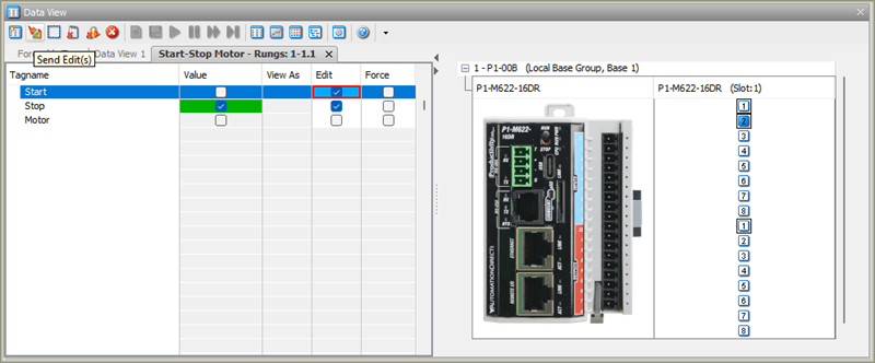
You can also toggle inputs directly from the Data View by checking the Edit box next to a tag and clicking Send Edit(s). This is another way to drive inputs in the simulator, and it works well when you want to control specific tags by name rather than clicking graphical I/O points.
This flexibility is one of the strengths of the Productivity Suite simulator—multiple ways to interact with your program, whichever suits your workflow.
Making Program Changes While Using the Simulator
One of the best uses of the simulator is testing program modifications before deploying them to live hardware. Let’s say we wanted to test changing the stop button input to normally closed in our circuit. Here’s the workflow:
- Go offline from the simulator by clicking the Offline icon or CPU | Offline
- Make your ladder logic changes in the editor. We will change the stop from normally open back to normally closed.
- Save the program.
- Restart the simulator (CPU | Simulator)
- Transfer the updated program (File | Transfer Project | To CPU)
- Put it back in Run (CPU | Run)
- Test your changes
Watch the video below to see this in action.
This is a fast, risk-free way to iterate on your code. No hardware is at risk, no process gets interrupted, and you build confidence in your changes before they go live. In a real industrial environment, this kind of pre-testing is invaluable.
The simulator supports online editing in the same way as the physical P1-M622-16DR. This means you can modify your ladder logic while the simulator is running and transfer the changes without stopping the program scan. This is a great way to practice the online editing workflow in a safe environment before using it on live hardware.
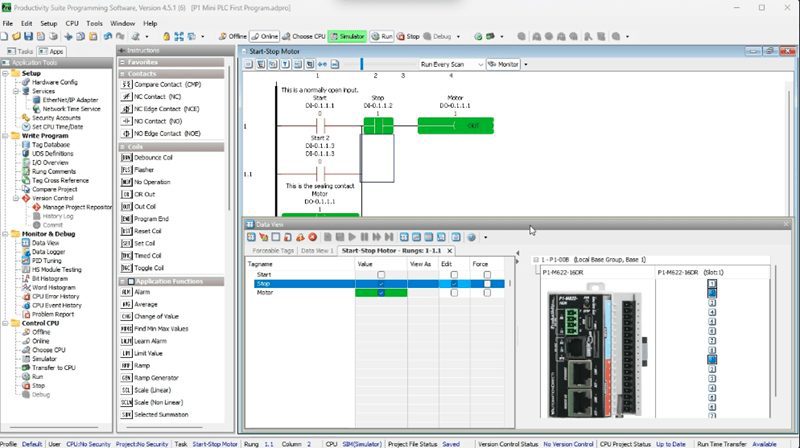
We will demonstrate by adding a second Start button input (DI-0.1.1.3) in parallel with our existing Start contact. We will also change the Stop contact back to normally open.
Steps:
- With the simulator running and the program in Run mode, make changes in the ladder diagram. We will change the stop normally closed contact back to the normally open contact. The ladder editor will display icons on the left side of the ladder logic to indicate pending online edits.
- Locate Rung 1 of our start-stop circuit. Click on the existing Start contact (DI-0.1.1.1) to select it.
- Add a new Normally Open contact in parallel below the Start contact. Assign it the tag DI-0.1.1.3 and give it a description of Start 2.
- Your rung should now show both DI-0.1.1.1 and DI-0.1.1.3 as parallel start inputs, with the sealing contact.
- Save your program.
- Select the Run Time Transfer icon on the toolbar (or go to File | Transfer Project | Run Time Transfer). A confirmation window will appear — click Yes.
- The updated ladder logic transfers to the simulator while the scan continues running. The icons next to the rungs have been removed, indicating that the changes are now live.
Test the change:
- In the IO View, click Input 3 (DI-0.1.1.3) — the Motor output should energize, proving the second Start input is working.
- Click Input 3 again to release it. The Motor stays ON due to the sealing contact.
- Click Input 2 (DI-0.1.1.2) to activate Stop. The Motor turns OFF.
The circuit now has two Start inputs, and we made that change without stopping the simulator. This is exactly the same workflow you would use on the physical PLC — practicing it here first builds the confidence to do it safely on a running machine.
Stopping the Simulator and Returning to Hardware
When you are finished with the simulator, click the Offline icon or select CPU | Offline from the main menu. The connection to the simulator will close.
Important: After disconnecting from the simulator, the software will remember it as the last connection. When you are ready to connect to the physical P1-M622-16DR, you must select Choose CPU from the toolbar. This will open the CPU Connections window where your physical PLC will be listed if it is connected via USB-C or Ethernet. Select your PLC and click Connect.
If the program in your physical PLC is different from the one currently open in the software, a Project Differences window will appear. Select No, Use PC Project to keep the version you developed and tested in the simulator. Then transfer the project to the hardware using the same Transfer Project to CPU step as before.
Your thoroughly tested program is now running on the real hardware.
Watch the video to see this in action.
Why Use the Simulator?
If you take nothing else away from this post, remember these three scenarios where the simulator is worth its weight in gold:
1. You don’t have the hardware yet. Hardware lead times happen. Use the simulator to develop and test your complete program so that when the P1-M622-16DR arrives, commissioning is a matter of hours—not days.
2. You want to test a change on a live system. Use the simulator to verify the logic change first. When you’re confident it’s correct, go to the physical hardware and use online editing (as we covered in our last post) to deploy it.
3. You’re learning. The simulator is the perfect environment for students and new PLC programmers. Make mistakes, experiment, and understand how the logic behaves—without any consequences. This series is built on that philosophy.
Watch the video below to see the Productivity Suite Simulator in action with our P1-M622-16DR start-stop motor circuit.
Productivity Mini PLC P1-M622-16DR from AutomationDirect
Overview Link (Additional Information on the Unit) Configuration (Configure and purchase a system – BOM) User Manual and Inserts (Installation and Setup Guides) Productivity Suite Programming Software (Free Download Link)
This software contains all of the instruction sets and help files for the Productivity Series.
Next time, we will look at the tag database and numbering systems in the Productivity Mini PLC P1-M622-16DR.
Watch on YouTube: P1-M622-16DR Mini PLC: Your Simulator Adventure Starts Now!
If you have any questions or need further information, please contact me.
Thank you,
Garry
Related Posts:
- Test Real PLC Controllers FREE – No Hardware Needed!
- P1-M622-16DR Mini PLC First Program: Start-Stop Motor Circuit
- P1-M622-16DR Mini PLC Online Editing and Fail-Safe Wiring
There are many PLC manufacturers offering various hardware and software. All programmable logic controllers share similar basic features. Here is how I would approach learning about basic PLCs.
Once you are familiar with the basics of the PLC, you will learn the specifics of the controller you will be programming.
This is the easiest way to learn about PLC programming.
Here are the controllers that we have covered or are covering at ACC Automation:
LS Electric XGB PLC Series
BRX Do-More Series (Do-More Designer Software + Simulator)
Productivity Series P1000 / P2000
Click PLC Series
Omron CP1H Series
Horner XL4 PLC Series
Arduino Opta PLC
The EasyPLC Software Suite is a comprehensive package that includes PLC, HMI, and machine simulator software. This allows you to make a digital twin. See below to receive 10% off this software. This PLC learning package contains the following:
Easy PLC – PLC Simulation will allow programming in Ladder, Grafcet, Logic Blocks, or Script.
HMI System – Easily create a visual human-machine interface (HMI)
Machine Simulator – A virtual 3D world with real-time graphics and physical properties. PLC programs can be tested using the EasyPLC or through other interfaces. (Modbus RTU, TCP, etc.)
Machine Simulator Lite – Designed to run on Android Devices.
Machine Simulator VR – Virtual Reality comes to life so you can test, train, or practice your PLC programming.
Purchase your copy of this learning digital twin package for less than $95 USD for a single computer installation or less than $110 USD to allow access on multiple computers.
Receive 10% off the investment by typing in ACC in the comment section when you order.
Learn PLC programming the easy way. Invest in yourself today.
Examples of PLC program development using the five steps.
Click PLC – Easy Transfer Line Programming – Video
Productivity PLC Simulator – Chain Conveyor MS – Video
Five Steps to PLC Program Development – Die Stamping
PLC Programming Example – Process Mixer
PLC Programming Example – Shift Register (Conveyor Reject)
PLC Programming Example – Paint Spraying
PLC Programming Example – Delay Starting of 7 Motors
PLC Programming Example – Pick and Place
PLC Programming Example – Sorting Station (Shift Register)
PLC Programming Example – Palletizer
If you’re like most of my readers, you’re committed to learning about technology. The numbering systems used in PLCs are not difficult to understand. We will walk through the numbering systems used in PLCs. This includes Bits, Decimals, Hexadecimal, ASCII, and Floating Points.
To get this free article, subscribe to my free email newsletter.
Use the information to educate others on how numbering systems work. Sign up now.

The ‘Robust Data Logging for Free’ eBook is also available as a free download. The link is included when you subscribe to ACC Automation.