
We will look at a PLC basic tutorial of a paint spraying station. Following the five steps to program development, this PLC programming example should fully explain the procedure for developing the PLC program logic. Ladder logic will be our PLC programming language.
We will use the Do-more Designer software, which comes with a simulator. This fully functional program is offered free of charge at automation direct.
Define the task – PLC Paint Spraying Example.
What has to happen?

Paint spraying system where boxes are fed by gravity through a feeder magazine one at a time onto a moving conveyor belt. Upon the start signal, boxes are pushed towards the conveyor by valve 1. This cylinder extends and retracts; operating switches S1 and S2 respectfully. A spraying nozzle paints each box as it passes under the paint spray controlled by valve 2. A sensor (S3) counts each box being sprayed. When six boxes have been painted, valve 2 shuts off (paint spray), and valve 1 (cylinder) stops moving boxes onto the conveyor. Three seconds later, the conveyor stops moving, and the hopper with its load moves forward (valve 3), where it is emptied. Ten seconds later, the hopper returns to its original position. The cycle is then complete and waits for a start signal again.
Define the Inputs and Outputs – PLC Paint Spraying Example
Inputs:
Start Switch – On/Off (Normally Open) – NO
Stop Switch – On/Off (Normally Closed) – NC
S1 – Valve 1 (cylinder retract) On/Off – NO
S2 – Valve 1 (cylinder extend) On/Off – NO
S3 – Box Detected- On/Off – NO
Outputs:
Motor – On/Off (Conveyor Run)
Valve 1- Cylinder to feed boxes – On/Off
Valve 2- Paint Spray – On/Off
Valve 3- Cylinder to move hopper – On/Off
Develop a logical sequence of operation – PLC Paint Spraying Example
Fully understanding the logic before starting to program can save you time and frustration.
Sequence Table: The following is a sequence table for our paint spraying application.
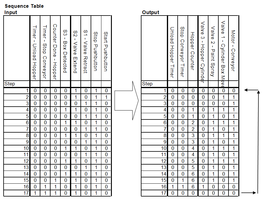
1 – Input / Ouput ON
0 – Input / Output OFF
x – Input / Output Does not Matter
When the power goes off and comes on, the sequence will continue. This means that we must use memory retentive areas of the PLC. The stop push button will stop the sequence. The start will resume until the end.
Develop the PLC program – PLC Paint Spraying Example.
The best way to see the development of the programmable logic controller program is to follow the sequence table along with the following program. You will see the direct correlation between the two and understand the process well.
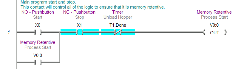
This is the main process to start and stop bit. V0:0 is used because it is memory retentive.
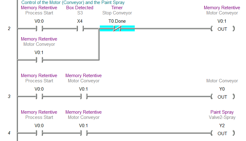
Control of the Motor (Conveyor) and the paint spray is done with the V0:0 contacts in front of the actual PLC output. The conveyor and paint spray will stop when timer 0 is done. This is the delay after the last box is detected to allow the box to be painted and loaded onto the hopper.
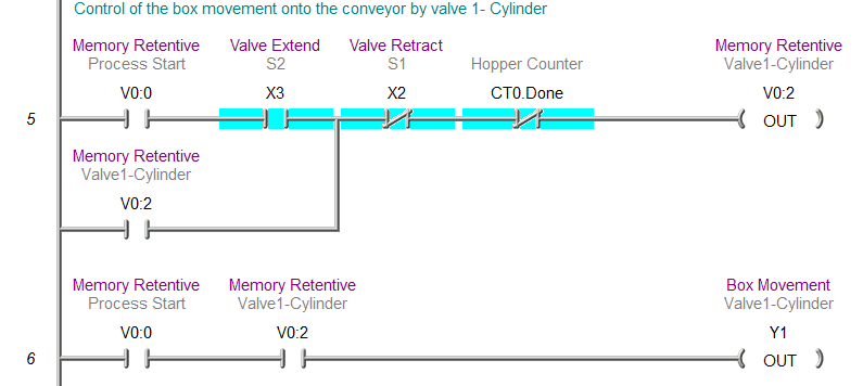
Control of the box movement onto the conveyor. As long as we have the process started and the hopper count is not complete, this will allow the cylinder to put boxes on the conveyor.
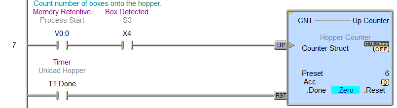
Count the number of boxes in the hopper via S3. The counter is memory retentive.
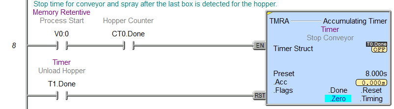
A timer to stop the conveyor and spray after the last box is detected for the hopper. This will allow time for the package to be sprayed and loaded into the hopper.
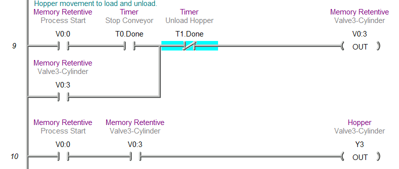
Hopper movement to load and unload the boxes.
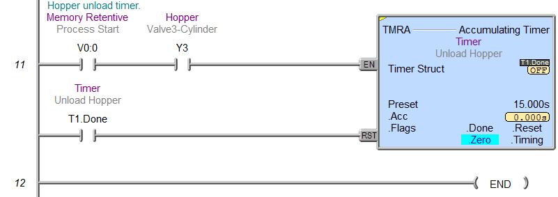
The hopper unload timer is to unpack the boxes and will then trigger the reset conveyor timer, box counter, and the process start bit (V0:0).
Test the program – PLC Paint Spraying Example.
Test the program with a simulator or actual machine. Make modifications as necessary. Remember to follow up after a time frame to see if any problems arise that need to be addressed with the program.
Watch on YouTube: PLC Programming Example – Paint Spraying
If you have any questions or need further information, please get in touch with me.
Thank you,
Garry
If you’re like most of my readers, you’re committed to learning about technology. Numbering systems used in PLCs are not challenging to learn and understand. We will walk through the numbering systems used in PLCs. This includes Bits, Decimals, Hexadecimal, ASCII, and Floating Points.
To get this free article, subscribe to my free email newsletter.
Use the information to inform other people how numbering systems work. Sign up now.

The ‘Robust Data Logging for Free’ eBook is also available as a free download. The link is included when you subscribe to ACC Automation.