We will be creating our first Productivity 2000 Series PLC program. This will be done in ladder logic. The default physical IO and PLC task management will be discussed. Previously we communicated to our productivity 2000 PLC and automatically created the hardware configuration. We also set the hot-swap feature of our physical input and output cards on the controller.
 We will now write our first PLC ladder logic program in our Productivity 2000 Series controller. This will be a simple start-stop circuit. We will download and then run the program, monitoring the ladder logic using the Productivity Suite software. Let’s get started.
Previously in this Productivity 2000 series PLC, we have discussed:
P2000 Hardware Features – Video
Productivity Suite Software Install – Video
Communication (System Configuration) – Video
Productivity 2000 Series PLC Default Tag Names
Previously we configured the inputs and outputs on our productivity 2000 PLC system. Default tags were assigned to each of the IO cards on the rack.
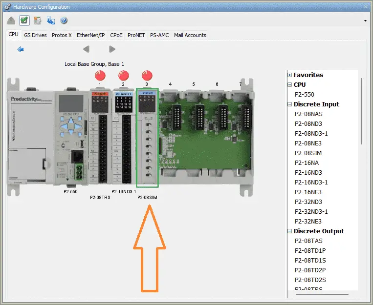 Double-clicking on the IO card in the hardware configuration window will call show you the tag assignments.
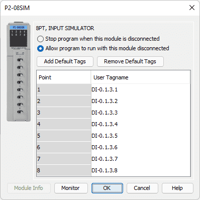 These are the default assignments for the 8 point simulator input card. The switches are numbered 1 to 8 and are assigned a User tag name.
Tag names follow the following format for discrete IO points: AAAAA-B.C.D.E
AAAAA – DI – Discrete Input Point
– DO – Discrete Output Point
– MST – Module Status (Ex. Blown fuse or error bits)
B – Base Group Number – The local base group with the CPU is 0
C – Base Number – The base with the CPU is 1.
D – Slot Number – Slots are labeled from the right of the CPU starting with 1.
E – Item Number – This would be the IO point.
Example: If we want the third switch on our simulator module this would be DI-0.1.3.3. The simulator input (DI) is located on the CPU base (-0). The input module is on the CPU rack (1) in the third slot (3). The third item number (3) would be the third switch on the card.
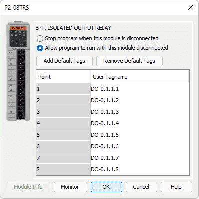 Here are the default tags for our output relay card. We can tell from the addresses that this comes from the CPU rack in slot 1 next to the CPU itself.
Names can be easily changed here or through the tag database that we will see later. However, you see that the nomenclature used for the default assignments makes it easy to tell the exact location of the input or output point.
Productivity Tag Database
The Tag Database allows adding, deleting, and editing tags in a project.
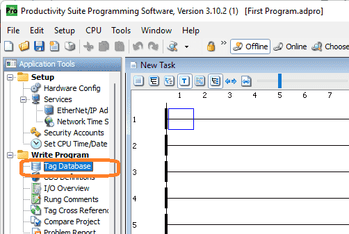 The Tag Database window can be accessed by selecting Tag Database from the Edit menu or by selecting Tag Database from the Write Program folder of the Application Tools panel.
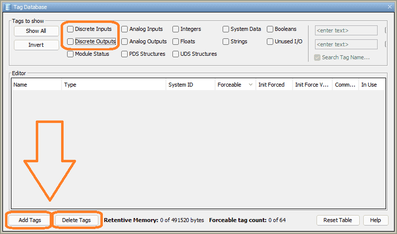 The tag database window will be displayed. At the bottom of this window, you can see where we can add or delete tags in our project. Select discrete inputs and outputs on the tags to show the menu.
 All of our available discrete inputs and outputs will not be shown in our window. This location will allow us to change the names of any of the tags that we have created.
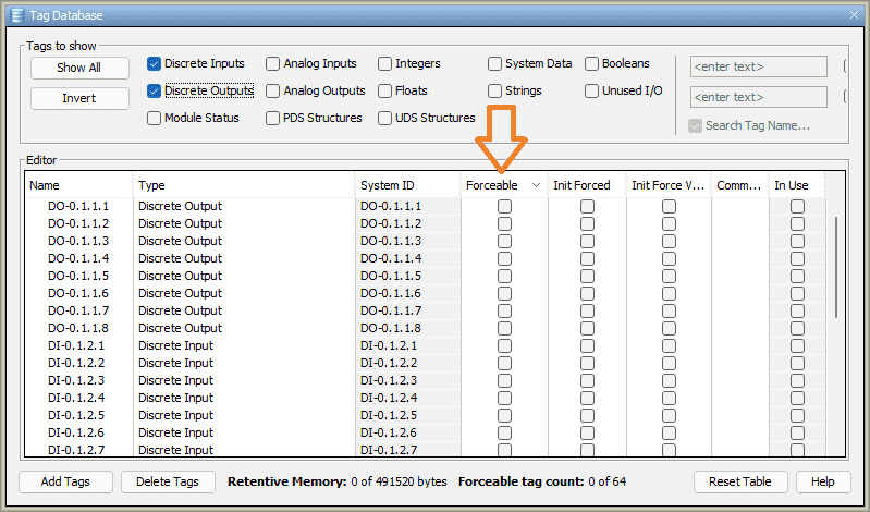
Note: The System ID tag has the same name as the default name tags.
The Forceable column allows the tag to be forced using Data View. A Maximum of 64 Tags may be selected as Forceable at any given time. Forcing an input or output will allow you to set the status of the bit on/off independent of the program scan. This is helpful when troubleshooting your ladder logic program.
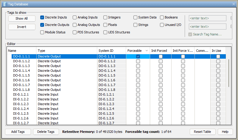 Turn on the Forceable bit for the DO-0.1.1.1. Select the X in the top right-hand corner of the window to close the tag database window.
Productivity Task Management
A productivity PLC program can be divided up into tasks. The task management window will show you how all of the programmed tasks are executed. (logic solved)
 “New Task” is the default name for all new projects like this one. The Task Management Panel allows you to add, edit and delete Tasks (ladder programs) within a project file. The Task Management Panel is displayed on the Main Screen and can be placed where desired. If the Task Management Panel is not displayed, it can be accessed from the main menu |Tools | Task Management Panel.
The Task Management Panel provides five Task Management folders:
– Run First Scan Only – Tasks in this folder are executed only on the First Scan when going to Run. These Tasks execute in the order they appear in the folder, and they execute before Tasks in the Run Every Scan and Run Every Second folder.
– Run Every Scan – Tasks in this folder are executed Every Scan during Run. These Tasks execute in the order they appear in the folder, and they execute before Tasks in the Run Every Second folder.
– Run Every Second – This folder is for lower priority tasks that do not need to execute Every Scan. Tasks in this folder are executed once per second during Run. These Tasks execute in the order they appear in the folder, and they execute after Tasks in the Run Every Scan folder. Please note, the one Second timer that triggers Tasks in the Run Every Second folder is not zeroed by a transition to Run.
– Run When Called – Tasks in this folder are executed only when called using a Call Task instruction.
– Disable Task – Tasks in this folder are not executed. Placing a Task here disables it.
We will use the default run for every scan task for our first program.
Productivity 2000 PLC First Program
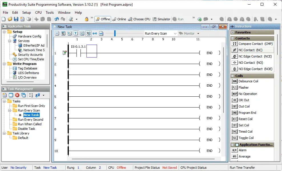
Instructions for our ladder logic are located on the right-hand side of the Productivity Suite Programming Software by default. You can move this window around to any location. If the instruction window is not being displayed then you can select it from the main menu | Tools| Instruction List.
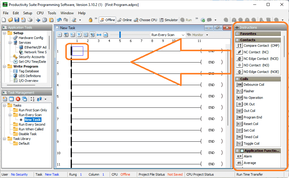 There are three ways to write the logic in the task. You can click and drag the instruction from the instruction list to the location that you want. Double-clicking the instruction will place it at the location of the cursor (blue outline) on the task. The third method is to use shortcut keys.
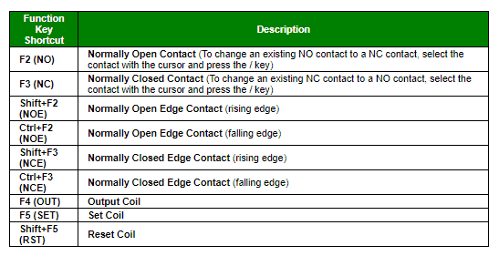 Here is a list of function key shortcuts. You can see a full list by selecting F9 on the keyboards or using the main menu | Help | KB Shortcuts.
Add a normally open NO contact to our first rung.
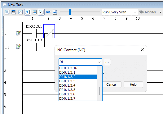
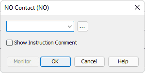 As you type the name of the first switch on our simulator the pull-down menu will populate with just the items that match.
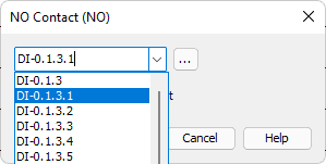 Select DI-0.1.3.1. Select OK.
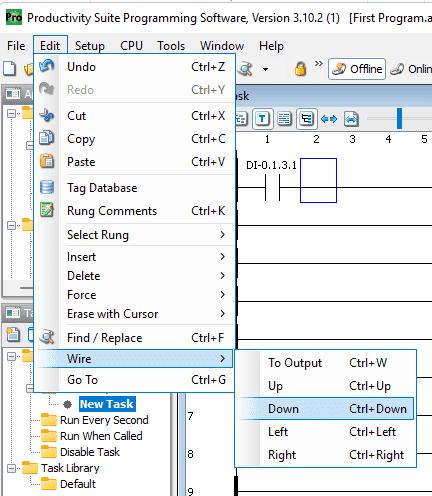
 With the cursor now next to the instruction that we just inserted we will now draw a vertical line down. We can use the keyboard combination of Ctrl + Down arrow, or from the main menu select Edit | Wire | Down.
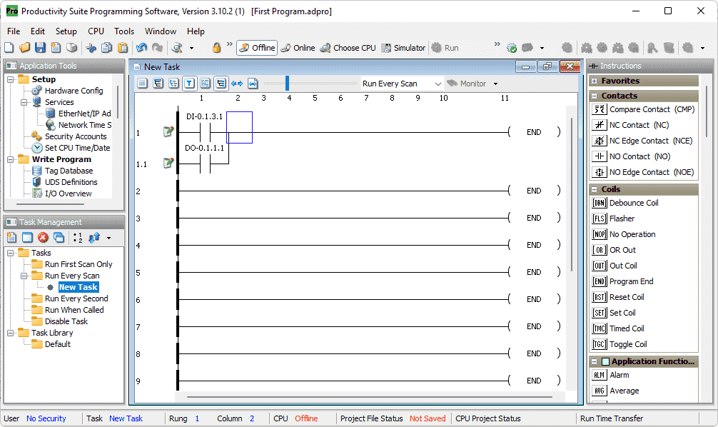
 Move the cursor manually under the previous contact. Double click on a NO Contact. Enter the address of DO-0.1.1.1. This will be the sealing contact for the output.
 Put a normally closed contact NC Contact next to the previous ones. Enter the address of DI-0.1.3.2. This will be our stop contact for our circuit.
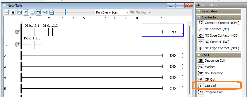
 Move the cursor to the end of the rung. Under the coils heading in the instructions, double click on Out Coil.
 Type in the same output tag as we used for the sealing contact.
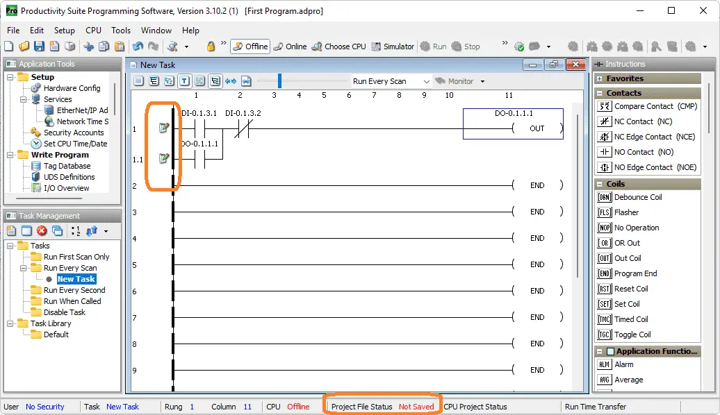 Our ladder logic program is now complete. You will see the pen and paper icons next to the rung and the project file status as not saved. Save our program by selecting the icon or use the save under the main menu | File.
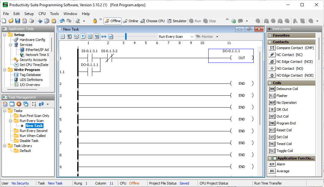 Our program is now saved. See the video below to watch how this programming is done.
We can now transfer our ladder logic program to the productivity 2000 controller.
Download and Monitor Productivity 2000 PLC Program
On the main menu select the choose CPU icon. You can also use the main menu | CPU | Choose CPU.
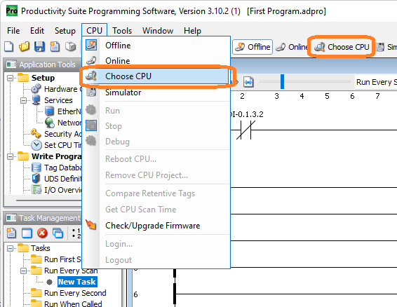 The online option can also be used. This will connect to the physical hardware the same way the software connect previously. If you are unsure, then select the “Choose CPU” to ensure you have the correct method of connection.
Note: A new project will default to the simulator for online.
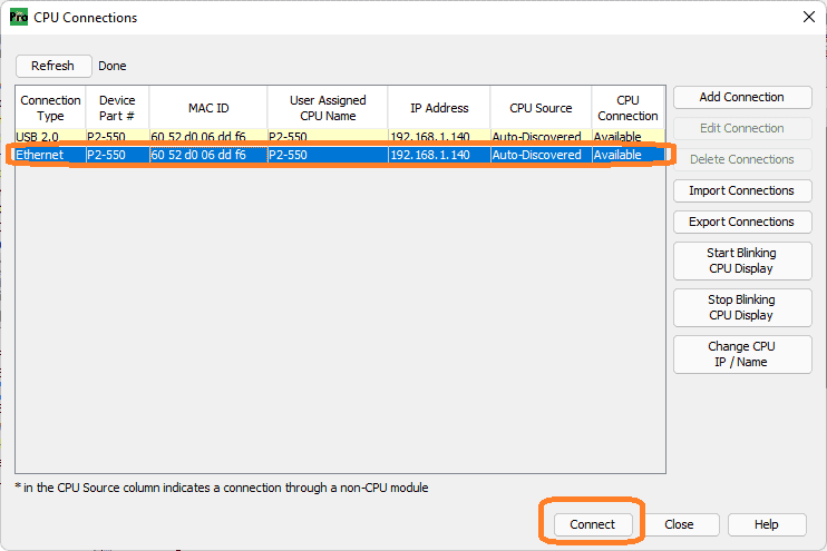 Select the Ethernet connection on the CPU connections window by clicking on it. This will highlight the option in blue. Now click the connect button on the bottom right of the window.
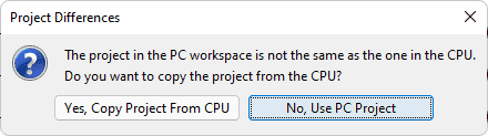 The productivity suite programming software will now establish communication with the controller. It will see the differences in the computer (PC) and the PLC (CPU) programs. Since we want to download this program to the PLC, select “No, Use PC Project”.
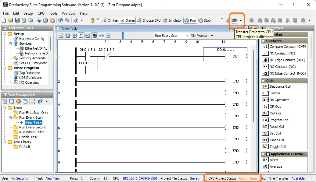 The CPU project status will be out of date at the bottom of the productivity suite programming software. This is because of the differences between the computer and PLC. Select the transfer project o CPU icon.
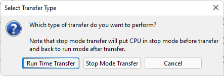 There are two ways to transfer to PLC. Stop mode transfer will place the PLC in stop mode. The program will then be sent to the controller. The PLC can then be placed back in run mode. Run time transfer will hold the scan, transfer the new code, and then release the scan. The PLC continues to run while the transfer is happening. Select Run Time Transfer.
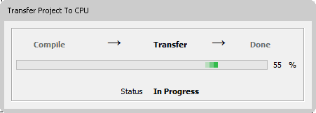 You will see the transfer project to CPU window percent. This will display as the new information is being transferred.
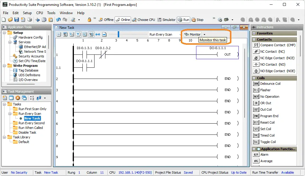 Once the transfer is complete, the CPU project status at the bottom of the programming window will now display up to date. Select monitor on the new task window.
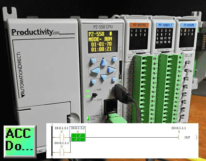
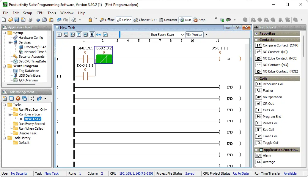 This will visually show you the status of the ladder logic code. Under the address of the contact, you will see an 0 or 1 to indicate the condition of the bit. The logical symbol will be red to indicate flow cannot happen, or green to indicate flow can happen. The idea of ladder logic is to allow logical flow from the left side to the right side. The outputs can then operate when the flow path is completed.
The scan of the PLC operates from left to right, top to bottom. The outputs of the previous rung are available for the next rung.
We can also monitor the inputs and outputs by using the data view.
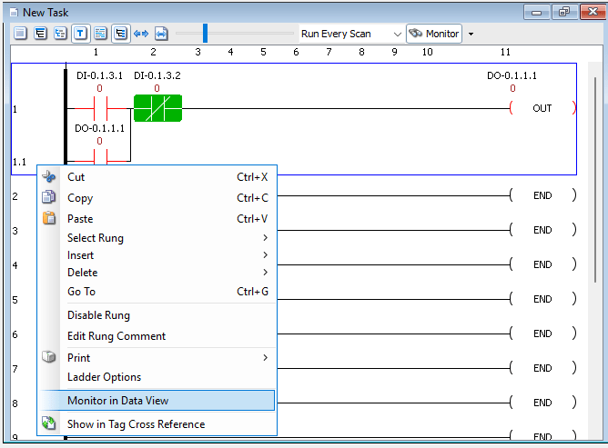 Click on the left-hand side of the first rung to highlight it with a blue outline. Right-click on this highlighted rung and select “Monitor in Data View”.
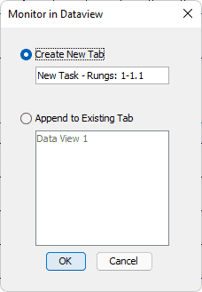 We will leave the default as “Create a new tab” with the default name. Select OK.
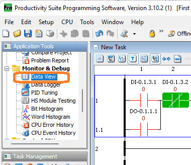 Select data view under the monitor and debug in the application tools. You can also select this using the main menu | Tools | Data View. The shortcut key combination is Ctrl + Shift + F3.
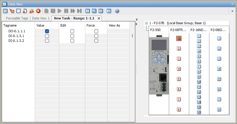 The data view window is split up into two sections. Select the tab on the left that we just created. The right-hand side will show the status of the hardware and conditions of the inputs and outputs visually.
Watch the video below to see this in operation.
Forcing Contacts in the Productivity 2000 PLC Program
In the data view window, select force on the output contact. This must be previously selected in the tag database as forceable. The edit column will determine if the contact is forced on or off.
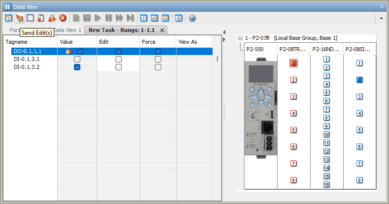 Select the send edit(s) icon to set the forces. A force will keep the input or output on or off independent of the logic being scanned in the PLC. This is a great way to troubleshoot your ladder logic program.
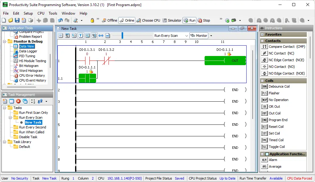 Viewing the ladder logic program the condition of the forced IO will show a locked picture beside it. This will indicate that this is not being controlled by the program logic. Watch the video below to see a demonstration of using force.
Productivity 2000 Features (P2000)
- CPU with 5 communication ports
- OLED message display on the CPU module
- Plenty of discrete and analog I/O modules
- Status displays on all discrete I/O modules
- OLED data display on analog modules
- P2-RS remote I/O expansion module, or use the Productivity1000 P1-RX remote expansion module to add even lower-cost remote I/O to your system
- FREE full-featured Productivity Suite software
- Programming with several ports – USB, Ethernet, Serial
- Hardware auto-discovery
- Hot-swappable I/O
- Choose from three wiring options
- Slim DIN rail density form factor:
- hardware – power supply, CPU, and seven modules in only 10-1/2 inches
- All project files (program, tag name database, and all the program documentation) in the CPU
- Run-time editing and debug mode on CPU
- Easy data logging with micro SD on CPU
- Secure Web server to access data files and system tags
- Easy drive and motion controller integration
- Coordinate motion control with PS-AMC allows control of up to 16 axes and synchronization of up to 4 axes
- Two-Year Warranty
Productivity 2000 Series PLC from Automation Direct
Overview Link (Additional Information on the Unit)
Configuration (Configure and purchase a system – BOM)
User Manual and Inserts (Installation and Setup Guides)
Productivity Suite Overview (Features of the fully functional free software package for the Productivity Family of PLC (PAC) controllers)
Productivity Suite Programming Software (Free Download Link)
This software contains instructions and helps files for the Productivity Series.
Watch on YouTube: Productivity 2000 Series PLC First Program
If you have any questions or need further information, please contact me.
Thank you,
Garry
If you’re like most of my readers, you’re committed to learning about technology. Numbering systems used in PLCs are not difficult to learn and understand. We will walk through the numbering systems used in PLCs. This includes Bits, Decimals, Hexadecimal, ASCII, and Floating Points.
To get this free article, subscribe to my free email newsletter.
Use the information to inform other people how numbering systems work. Sign up now.

The ‘Robust Data Logging for Free’ eBook is also available as a free download. The link is included when you subscribe to ACC Automation.