Creating a Node-RED Flow Program in the Click PLUS PLC C2-NRED Module
Node-RED is an innovative and powerful tool for connecting hardware devices, APIs, and online services. Regarding industrial automation, the Click PLUS PLC C2-NRED module takes things up a notch by integrating Node-RED, allowing users to create flows via a visual programming interface. Previously, we updated the Click Programming Software to version 3.70. The firmware in the Click CPU and C2-NRED Module were then updated to their latest versions.
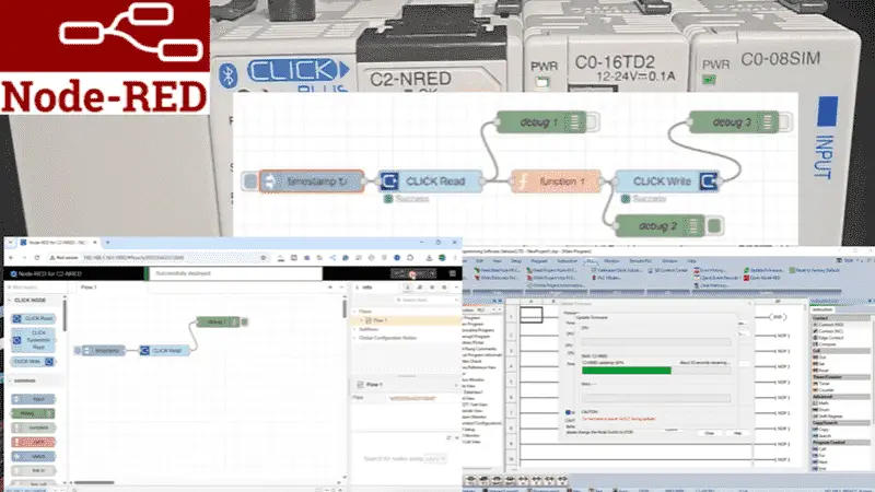
We will guide you through creating your first Node-RED flow program in the Click PLUS PLC C2-NRED module. We will read and write information to and from the Click PLC CPU. We will discuss saving and retrieving our flow programs and troubleshooting. Let’s get started.
Our entire Click series can be found here.
All of the previous information for the Click PLC can be applied to the Click PLUS. Previously, here are some of the things we covered:
Software Installation – Video
Click Software Establish Communication – Video
MQTT Communication – Video
Data Logging – Video
Real-Time Clock with Network Time Service – Video
Click Remote PLC Mobile App – Video
Mastering Click PLC Communication Modbus RS485! – Video
Unlock Click PLC & Machine Simulator Integration – Video
CLICK PLUS C2-NRED: Easy Install for PLC Module! – Video
The programming software and manuals can be downloaded from the Automation Direct website free of charge. Watch the video below to see how to update and install our C2-NRED module on our Click PLUS PLC.
Accessing Node-RED
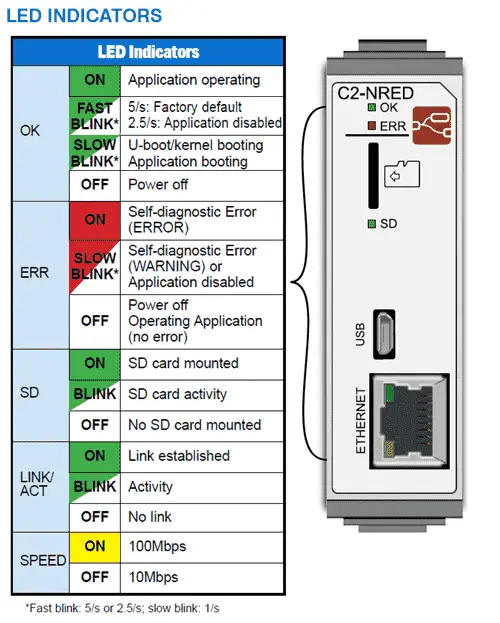
When first applying power to the Click system with the C2-NRED Module, it will take up to 45 seconds for the module to be booted. Here are the meanings of the lights on the C2-NRED card.
In our post “CLICK PLUS C2-NRED: Easy Install for PLC Module!” we updated the firmware in our Click PLUS CPU to version 3.70 and updated the firmware on our intelligent module C2-NRED. We then set up the CPU and C2-NRED to communicate on our network.
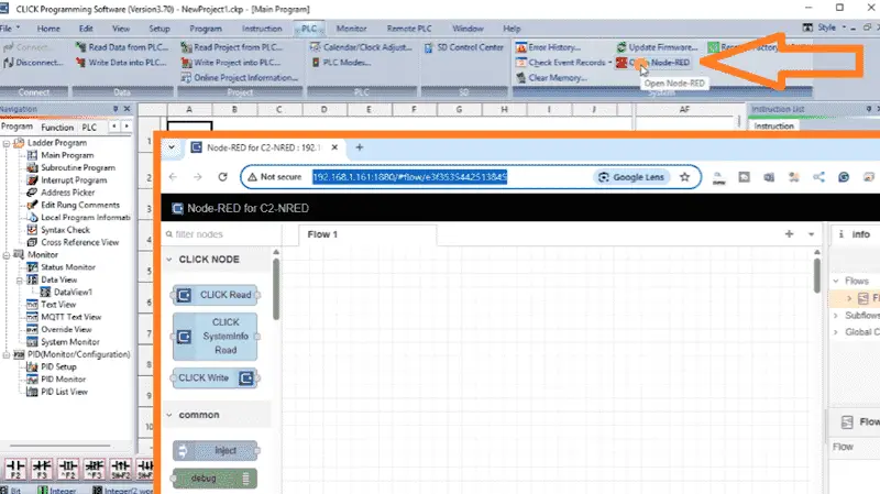
To start and program our node red module, select open Node-RED from the PLC tab of the main menu in the Click PLC Programming Software. Select the Ethernet option and select connect. Your default browser will open up, and we will see the node red programming screen for the C2-NRED module. Another way to start the Node-Red interface is to start a new tab in the browser and paste the URL address and port for the programming set/copied in the C2-NRED configuration screen in the Click PLC programming software.
What is Flow Programming?
Node-RED may feel unfamiliar to those with experience with Ladder Logic, the Graphical Programming Language (GPL), or scripting languages. On the other hand, individuals accustomed to scripting languages like JavaScript might find Ladder Logic in a CLICK PLUS PLC quite puzzling. Each of these three languages has its strengths, but combining them in the CLICK PLUS C2-NRED module opens up innovative approaches to industrial control and maker space/commercial applications.
Node-RED introduces a third type of programming, known as a Flow editor. Similar to Ladder logic, this editor is a GPL (Graphical Programming Language) and operates like a flowchart, where each node represents a specific function. These functions can range from simple tasks, such as checking a data value, to more complex operations, like calling a web server to retrieve a block of information.
Behind the scenes, Node-RED builds a JavaScript application and can even incorporate function blocks that are JavaScript subroutines.
Understanding the Node-RED Interface
The Node-RED interface consists of several panels:
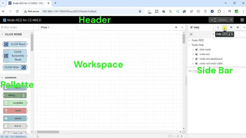
Palette – You can find nodes to drag into your workspace on the left.
Workspace – The central area where you build your flow.
Info Panel – Information about selected nodes is provided on the right.
Help Panel – This area will show you two areas. The Node-RED Help will show you the changes in this software version, and you can display the tour as we did before. Node Help will have all the help files for the nodes installed on the palette.
Debug Panel – This area lets you view outputs and log messages to help debug your flow. Troubleshooting your code becomes easy with the debug panel.
Config Panel – This will help configure your flows or specific nodes for your system.
Building Your First CLICK Read Flow
Let’s create a simple flow that reads an input from our Click PLUS PLC.
All the palette nodes can be dragged and dropped onto the workspace. Start by dragging an ‘Inject’ node from the palette to your workspace. This node will serve as our trigger. Now drag and drop a CLICK Read and debug node on the workspace.
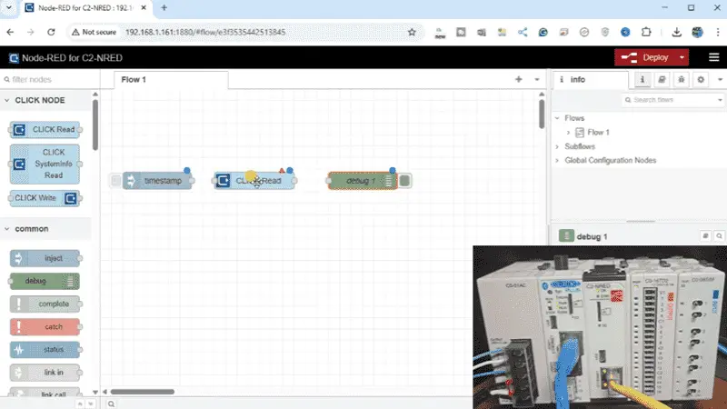
The red triangle means that there is something not right with the setup of this node. Double-click and set the addresses to read the input switches on our Click PLUS PLC. This is address 201 bits 1 to 8, so the size is 8. You will see that these settings are initially in red, so the red triangle was shown. The memory type can be selected for all the different Click PLC areas. The name that appears in the workspace for the node can change, but we will leave this as its default.
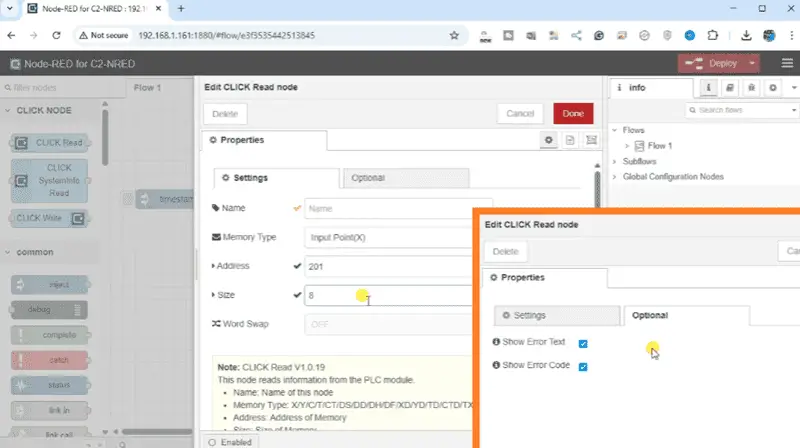
Under the option tab, select “Show Error Text” and “Show Error Code”. This will aid us in troubleshooting our code. Select Done. None of the nodes now have an error.
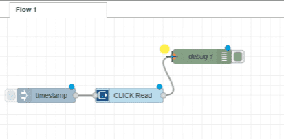
Join the nodes together by clicking the outputs to the inputs. Start with the inject node joined to the CLICK Read node. Then, the CLICK Read node is linked to the debug node.
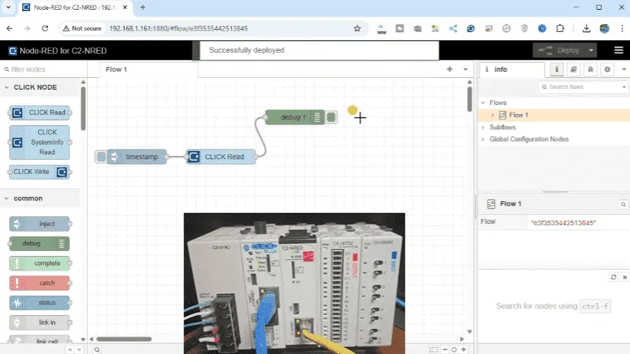
Once everything is connected and configured, click the ‘Deploy’ button. This action saves and runs your flow. A message “Successfully deployed” will be shown.
Select the debug tab on the right-hand side. This will show us the message sent from the CLICK Read to the debug.
Click on the button in the Inject node to trigger our flow. You should see the output in the Debug panel. This is the message object payload. Expanding this msg.payload, you will know we have a result, data, and result text. This is all of the information being sent from the CLICK Read node. Expanding the data, you will find an array representing all the switch conditions we requested. Change the switch state on the PLC and trigger the flow again. You will now see the updated switch conditions. Selecting the delete all in the debug window will clear the debug window. Notice that we also can see the “Success” indication under the CLICK Read node. This gives us a quick visual that indicates that our flow is working.
Adding A CLICK Write To Our Flow
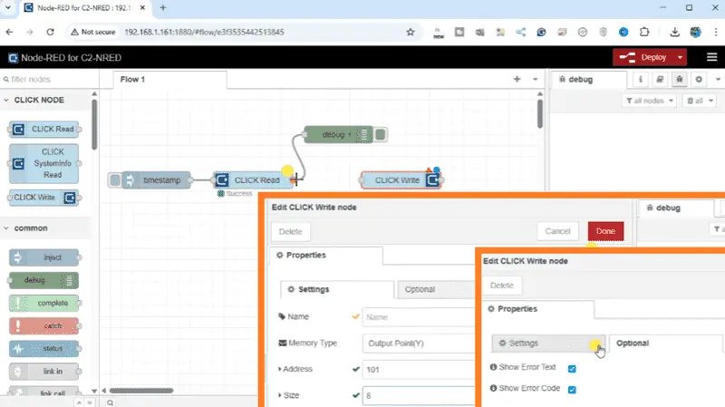
Dragging a ‘CLICK Write’ node from the palette to our workspace. Join the CLICK Read output to the CLICK Write input. The red triangle on the CLICK Write means we need additional information for this node. Double-click it. We will set the address to 101 and the size to 8. This represents the first eight outputs on the PLC. The memory type will show you the different areas we can write to in the Click PLC. Under the option tab, select “Show Error Text” and “Show Error Code”. Select Done.
Drag, drop, and connect another Debug node after the CLICK Write. Click the ‘Deploy’ button.
Select the injection node for our flow. We have an error. This is displayed under the CLICK Write node as well as for debug 2. The error is that the input payload is not an array.
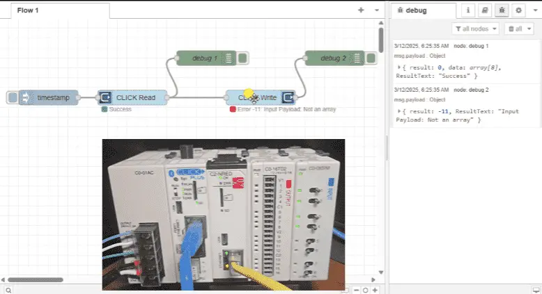
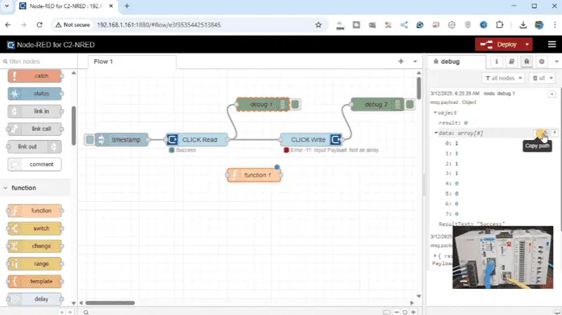
This is because our output from the CLICK Read is more than just an array. It also contains the result and result text. We can separate this information coming from the CLICK Read node by using a Function node. Drag and drop a function node onto our workspace. Looking at our debug message after the CLICK Read, we can find the path to the data array. Click on the copy path for the data.
Double-click on the Function node. The On-Message tab will be displayed. We can write Javascript within this function node. Paste our copy path for the data array from the CLICK Read node. Our Javascript line will read: msg.payload = msg.payload.data;
The semicolon at the end of the line is necessary for Javascript programming.
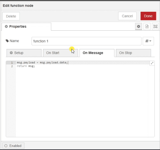
The Function Node also has tabs for Setup, On-Start, and On-Stop. The help menu will help you with how these tabs work. Select Done.
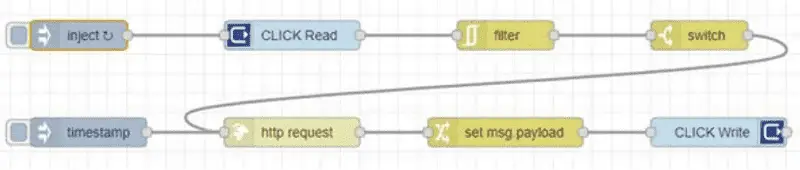
Join the Function node output to the CLICK Write input. Delete the Debug 2 node connection and join it with the output from the Function node. Add another Debug node to the output of the CLICK Write instruction. Deploy the flow. Ensure that the debug area window is clear and press the inject mode.
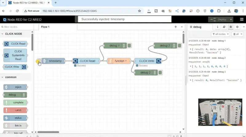
Our flow is now working. This is easily seen by the “Success” under each CLICK Read and Write node. In the debug window, we can see the output from debug 2 is now just an array of values, which are then written into the CLICK PLC. Changing the switch inputs on the PLC and clicking on the inject node will change the outputs.
Node-RED is an innovative and powerful tool for connecting hardware devices, APIs, and online services. Regarding industrial automation, the Click PLUS PLC C2-NRED module takes things up a notch by integrating Node-RED, allowing users to create flows via a visual programming interface. Previously, we updated the Click Programming Software to version 3.70. The firmware in the Click CPU and C2-NRED Module were then updated to their latest versions.
We will guide you through creating your first Node-RED flow program in the Click PLUS PLC C2-NRED module. We will read and write information to and from the Click PLC CPU. We will discuss saving and retrieving our flow programs and troubleshooting. Let’s get started.
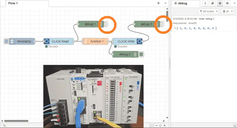
Debug nodes can be turned on or off by selecting the output on the node. Turn off Debug 1 and 3 from the Read and Write nodes. Deploy and inject the flow. We will only see the array read and written to our CLICK PLUS PLC.
Configure The Inject Node
Double-click the Inject node to configure it. We will leave the payload type as its default value (timestamp). We will set the inject time at regular intervals. This will set the frequency of when our flow will function.
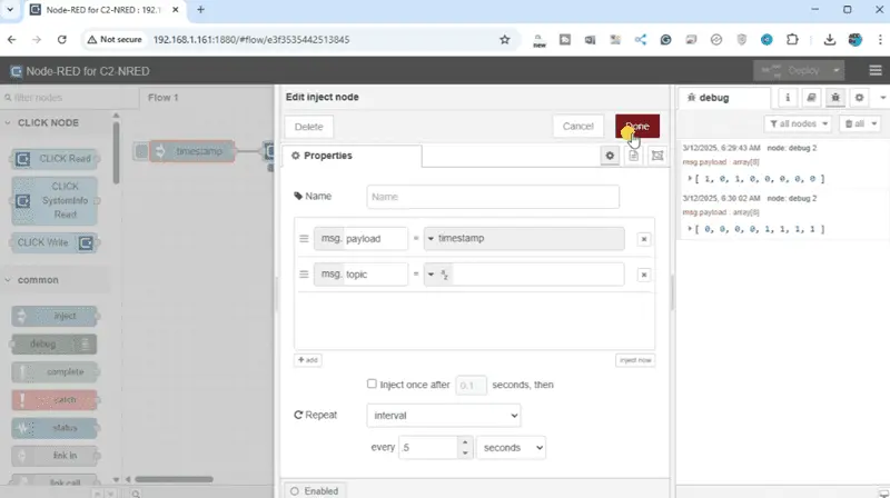
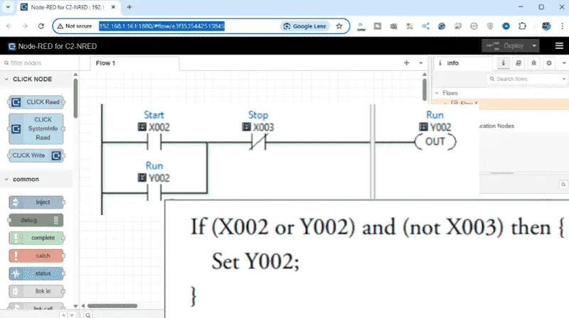
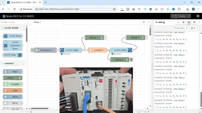
Select Done and Deploy. Our Click PLC inputs are being read and written every 0.5 seconds. Change the input switches to reflect in the Click PLC outputs. Remember that we only have an END statement in the Ladder Logic code. Node-RED is doing all of the control.
Saving The Node-RED Flow – Export / Import
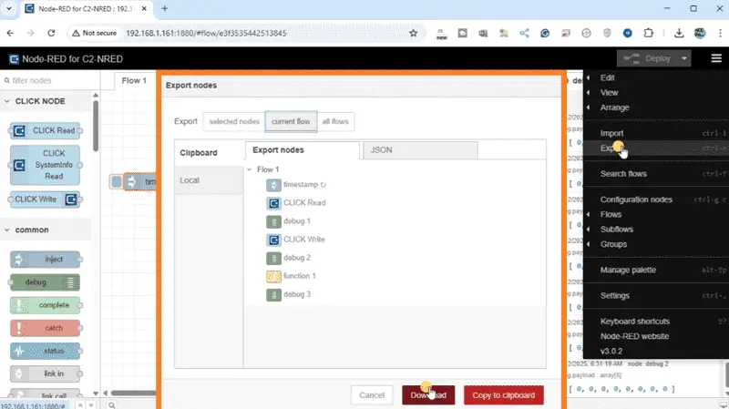
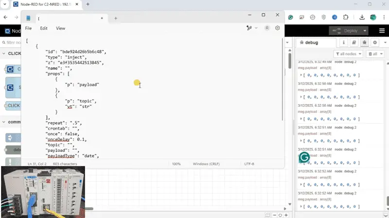
Click the pancake symbol beside the Deploy button. We can now select Export (ctrl + e). The export nodes window will be displayed. We can choose Selected, Current, or All Flows at this window’s top. Select Current Flow and then select Download. This will download a JSON file of your flow. You can rename this file for your Node-RED program.
Select the export again from the menu. After selecting what nodes or flows we want to save, click Copy to Clipboard. We can now open any text editing software like Windows Notepad and paste the JSON information copied to the clipboard.
The Import (Ctrl + i) is used to take the JSON file and restore your FLOW or FLOWS that have been saved.
Congratulations! You’ve successfully created your first Node-RED flow program within the Click PLUS PLC C2-NRED module. To learn more about programming with Node-RED, click here. Click here to learn more about the Click PLUS PLC.
This is just the beginning; you can expand your flows by adding more nodes, connecting to different devices, or integrating with APIs. With practice, you’ll unlock the vast potential that Node-RED offers for industrial automation and IoT solutions. Keep experimenting, and enjoy the process of learning and building!
Our Node-RED series can be found here.
Download the Click PLUS PLC Program, and Flow here.
Node-RED Links
Node-RED Organization Home Page
Getting Started – Run Locally
Node-RED running on Windows (Run at Startup)
Securing Node-RED
Node-RED Essentials Videos (Basics of the Editor)
Learn JavaScript Free
w3schools JavaScript Tutorial
learn-js.org
Node-Red JavaScript Primer
Modbus
Node-RED Modbus TCP and Serial
Dashboard – HMI
Node-RED Dashboard
Node-RED Dashboard extra nodes
SQL Database
Node-RED SQL Database
Node-RED SQL Plus – Execute queries and stored procedures
Modbus Learning Links:
Simply Modbus Frequently Asked Questions
Modbus TCP/IP Overview – Real-Time Automation
All You Need to Know About Modbus RTU – Video
Our entire series on the Click PLC can be found here.
The Click PLC can be programmed using free Click programming software from Automation Direct.
Here is a link to the software. Version 3.70
The entire Click PLC series before the Click PLUS release can be found here.
All previous posts and information are still valid with the Click PLC lineup.
YouTube Click Playlist
YouTube Click PLUS Playlist
Click and Click PLUS PLC Overview
Click and Click PLUS PLC Videos from Automation Direct
Watch on YouTube: Unleash Innovation: Node-RED Flow in Click PLC
If you have any questions or need further information, please contact me.
Thank you,
Garry
If you’re like most of my readers, you’re committed to learning about technology. The numbering systems used in PLCs are not difficult to learn and understand. We will walk through them, including Bits, Decimal, Hexadecimal, ASCII, and Floating Point.
To get this free article, subscribe to my free email newsletter.
Use the information to inform other people how numbering systems work.
Sign up now.

The ‘Robust Data Logging for Free’ eBook is also available as a free download. The link is included when you subscribe to ACC Automation.