We will now establish communication using four different methods from our computer to the new Click Plus controller. The click programming software version 3.00 will be used for the communication methods. Click Plus controllers allow you to program them through the micro USB port on every CPU. WiFi (Bluetooth Provisioning) is also available on some controllers. Ethernet and Serial ports may also be used for programming if they are present on your model of Click Plus.
We will be establishing PC to PLC communications using version 3.00 of the click programming software. Four different ways will be discussed on getting connected to the Click Plus controller to program. Let’s get started.
Our entire Click series can be found here. All of the previous information for the Click PLC can be applied to the Click PLUS.
Previously we looked at the following:
Software Installation – Video
The programming software and manuals can be downloaded from the Automation Direct website free of charge.
Watch the video below to see the connection of the Click Plus to the Click programming software version 3.00.
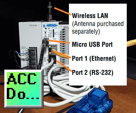
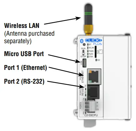
C2-03CPU
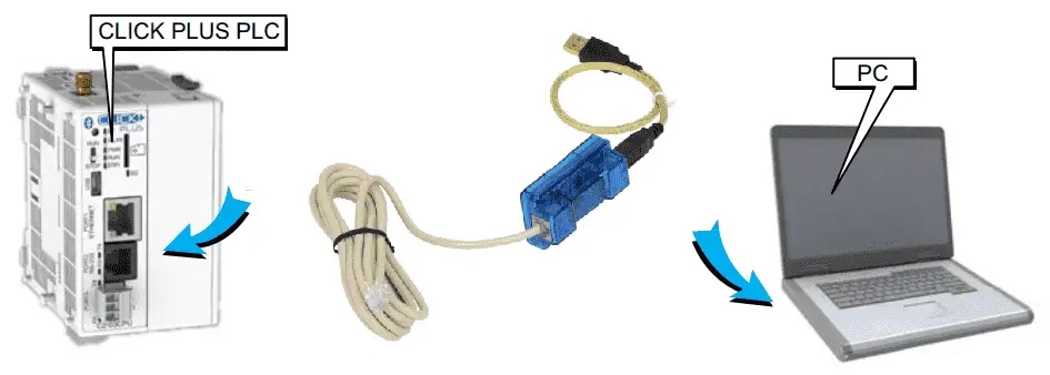
Click Plus Micro USB Connection
USB A to USB micro B Programming Cable Assembly
USB-CBL-AMICB6
All Click Plus CPUs have a micro USB to program the controller.
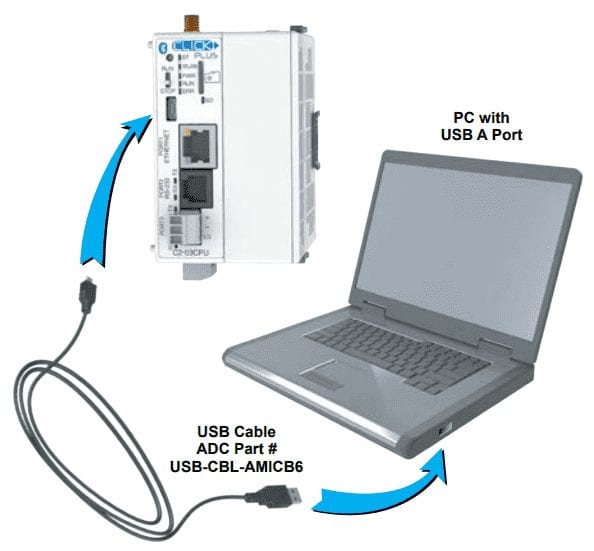
Note: Not all USB A to USB micro B cables are the same. If you cannot communicate with the controller, the first thing to do is change the cable unless this has been purchased from AD.
Plugin the USB cable.
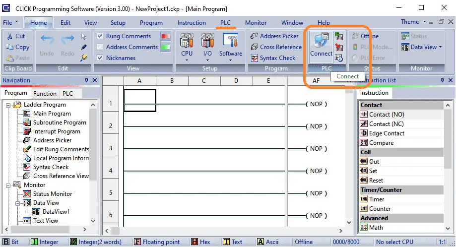
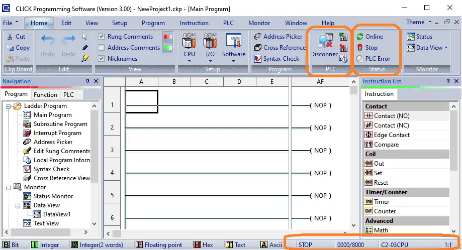
On the Home tab of the Click programming software select ‘Connect’. You can also use the main menu | PLC | Connect…
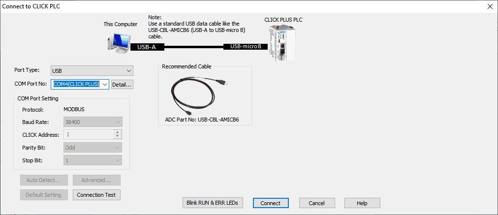
Select USB under the port type. Select the COM Port Number that will show the following:
COMX(CLICK PLUS) – Where X is the communication port on your computer.
This will load the correct driver that was installed during the installation of the click programming software.
Select connect.
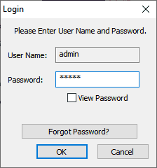
The login window will now be displayed. Since this is a new CPU the default password is ‘click’. Select the OK button.
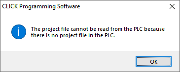
A warning message will now be displayed indicating that the project file cannot be read from the PLC because there is no project file in the PLC. Select OK.
We are now connected to our Click Plus controller.
On the Home tab, you can see the online status, errors, and current PLC mode. (Stop/Run) Under the PLC you can see the option now to disconnect. The bottom status bar will show the PLC mode, the number of rungs, and the model of click controller that is connected.
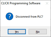
Select the disconnect from the home tab under PLC. Select yes to disconnect from the controller. We will now continue with the second method of communication.
Click Plus WiFi Connection
An antenna can be added to the Click Plus CPU. If you are using a metal enclosure for your panel then an external dome antenna can be used.
SE-ANT250
Wi-Fi/Bluetooth Dome Antenna (C2-02CPU & C2-03CPU only)
If your panel is not metal then a whip antenna can be used.
E-ANT210
Wi-Fi/Bluetooth Whip Antenna (C2-02CPU & C2-03CPU only)
(nonmetal enclosure only)
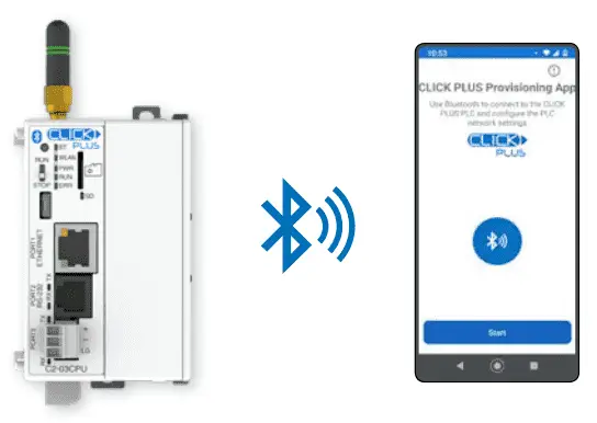
Bluetooth is used to set up the WiFi network. This is called provisioning. The Click Plus provisioning app is available for Android and iOS devices.
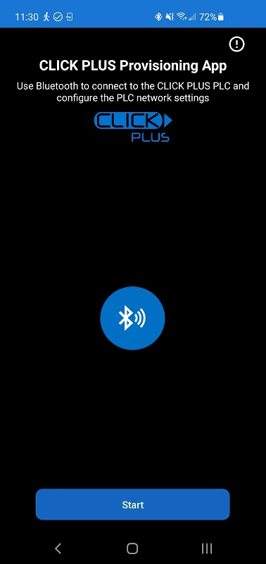
Install the appropriate app on your phone and hit the start button.
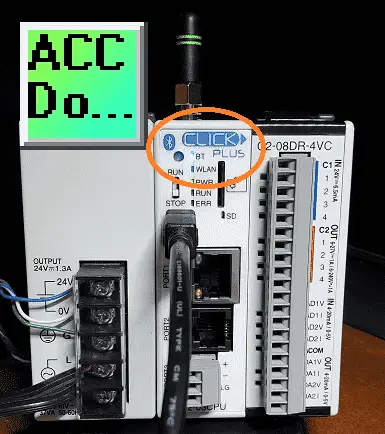
If the BT (BlueTooth) light is flashing, the click can be found on the network. If the light is off then the reset button must be pressed on the CPU to start the light flashing. These instructions are on the provisioning application. Continue following the instructions on the screen until the end.
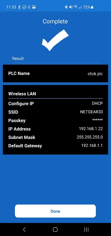
In our example, we have set up the Wireless LAN. The IP address has been determined by the DHCP server. Select done after the setup is complete.
Note: To determine the MAC address of the hardware, use the ping instruction to the IP address of the Click wireless or wired LAN device. This will then display the physical address.

Select connect from the home tab. On the connect to CLICK PLC window select Ethernet as the port type. The WiFi address that was just set up should now be displayed. Select connect.
Click Plus Ethernet Connection
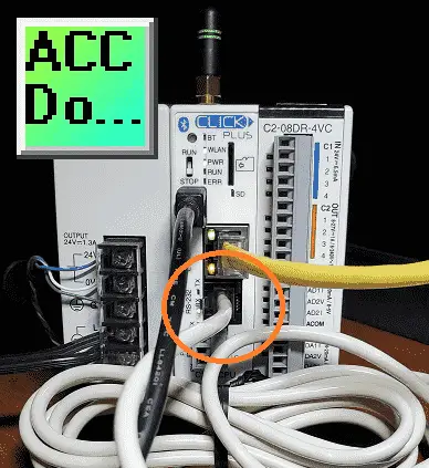
Connect an Ethernet cable to the port on the Click Plus PLC.
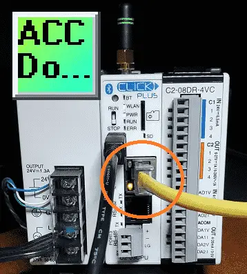
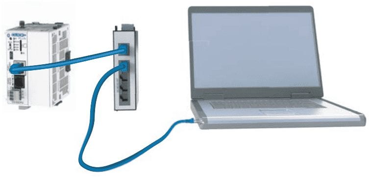
This port can be connected through your existing router or directly to your computer.
Select connect from the home tab. On the connect to CLICK PLC window select Ethernet as the port type. The WiFi address and wired address will now be displayed.
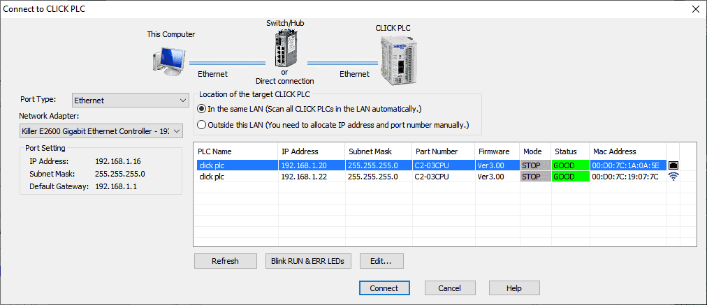
Select connect.
Click Plus Serial Connection
Connect the serial cable to USB adapter.
This is used because most computers today will not come with serial ports directly.
EA-MG-PGM-CBL
Connects to PC USB Port
Select connect from the home tab. On the connect to CLICK PLC window select USB as the port type. COM 6 in our case is the port in which the USB driver was loaded.
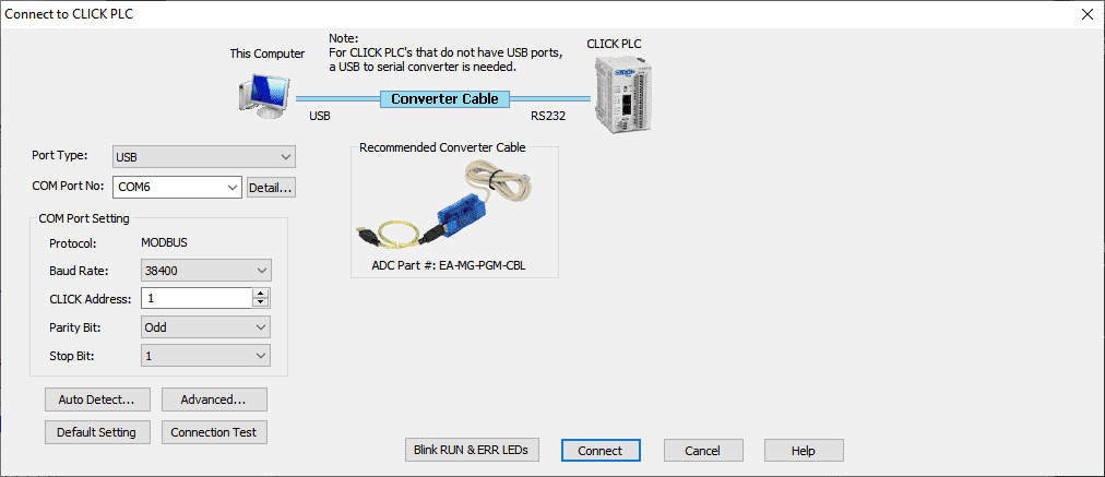
Select connect.
Watch the video below to see the communication connection in four different ways using the Click programming software.
Click PLC Support Links
The Click PLC can be programmed using free Click programming software from Automation Direct. Here is a link to the software.
Version 3.00
Version 2.60
The entire Click PLC series prior to the Click PLUS release can be found here.
All previous posts and information are still valid with the Click PLC line-up.
YouTube Click Playlist
YouTube Click PLUS Playlist
Click and Click PLUS PLC Overview
Click and Click PLUS PLC Videos from Automation Direct
Watch on YouTube: Click Plus Establish Communication
If you have any questions or need further information please contact me.
Thank you,
Garry
If you’re like most of my readers, you’re committed to learning about technology. Numbering systems used in PLCs are not difficult to learn and understand. We will walk through the numbering systems used in PLCs. This includes Bits, Decimal, Hexadecimal, ASCII, and Floating Point.
To get this free article, subscribe to my free email newsletter.
Use the information to inform other people how numbering systems work. Sign up now.

The ‘Robust Data Logging for Free’ eBook is also available as a free download. The link is included when you subscribe to ACC Automation.