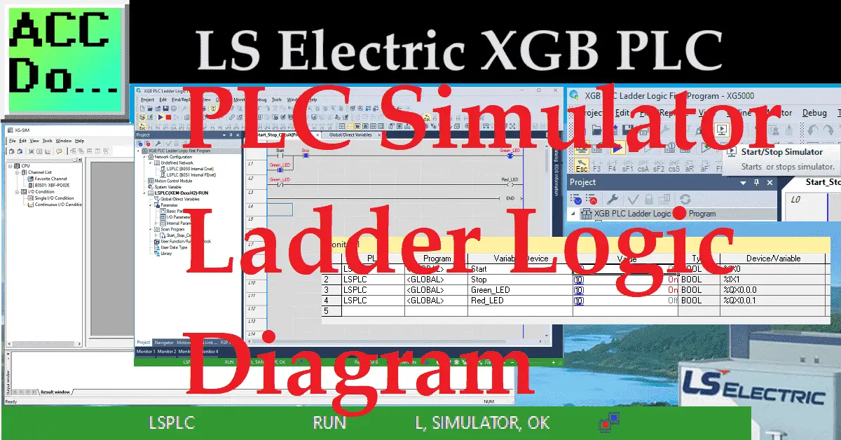
PLC Simulator is a convenient tool for testing and troubleshooting ladder logic programs in the XG5000 programming software. It allows you to simulate the operation of a programmable logic controller (LS Electric PLC) without needing actual hardware. This makes it a valuable asset for beginners and experienced programmers.
We will demonstrate how to effectively use the PLC simulator in the XG5000 programming software for ladder logic. Using the Start Stop circuit we developed last time; we will show how this can be simulated in the XG5000 programming software before downloading it to the actual XGB PLC. Let’s get started.
Previously in this LS Electric XGB series, we have done the following:
Transform Automation with LS XGB PLC: The Solution
– Unboxing and Powering Video
Install & Com w/ XG5000 PLC – Video
LS Electric XGB PLC Variables and Scope – Video
Wiring Discrete I/O to an XGB PLC – Video
XGB PLC Ladder Logic First Program – Video
See the list of references for the XGB PLC, including the frequently asked questions (FAQ) at the end of this post.
Open the XG5000 Programming Software
Open the XG5000 programming software on your computer. Once the software runs, we can open the start-stop ladder logic project we created last time.
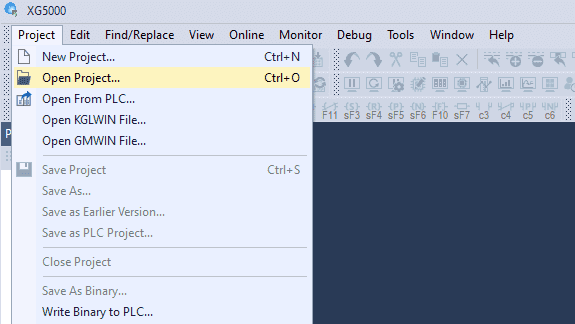
Select the open project icon on the main screen or select main menu | Project | Open Project… Alternatively, you can use the shortcut Ctrl + o.
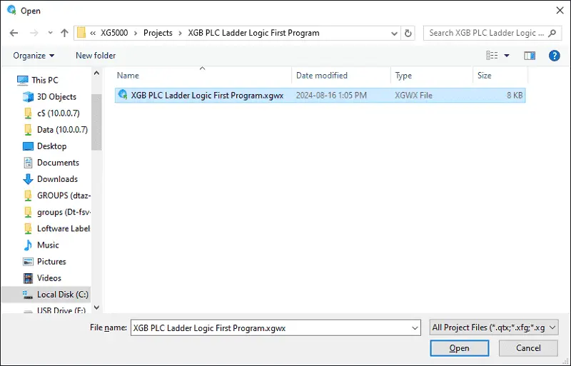
The default directory is located under C:\XG5000\Projects. Please select the project we created last time and choose Open.
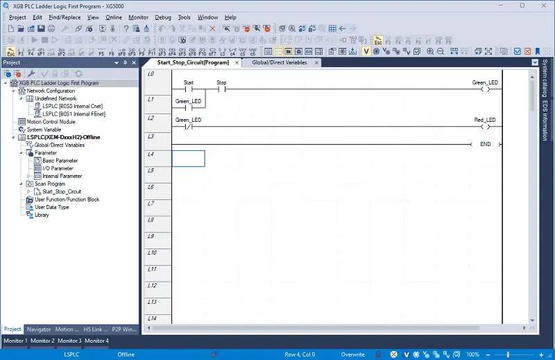
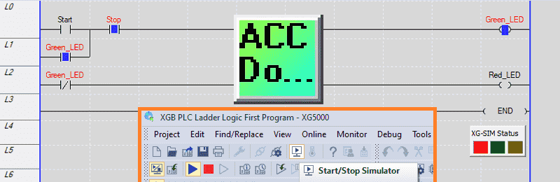
Our ladder logic diagram will now be displayed. We are offline to the controller due to the blue bar at the bottom of the XG5000 software window.
Start the PLC Simulator and Transfer the Program
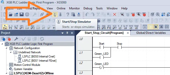
Start the PLC simulator by selecting the icon on the main screen.
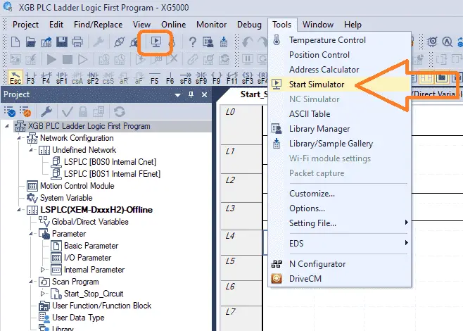
This can also be started by the main menu | Tools | Start Simulator.
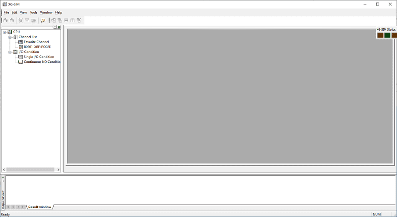
The XG-SIM window will first be displayed.
Then, the XG5000 will be shown with communication to the simulator. This is the red bar at the bottom of the XG5000 programming software.
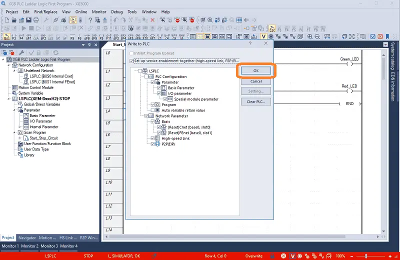
The Write to PLC window will automatically be displayed. XG5000 software treats the simulator like a PLC controller, and you must establish communication and transfer the program. We will leave all of the default settings the same and select OK.
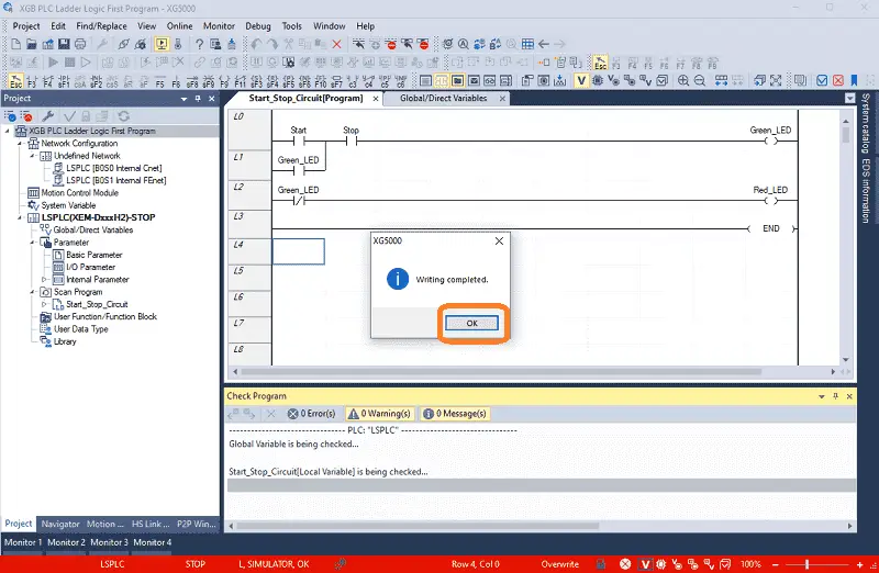
Our ladder logic diagram start-stop circuit will be loaded into the PLC simulator. The XG5000 writing complete message will be displayed. Select OK.
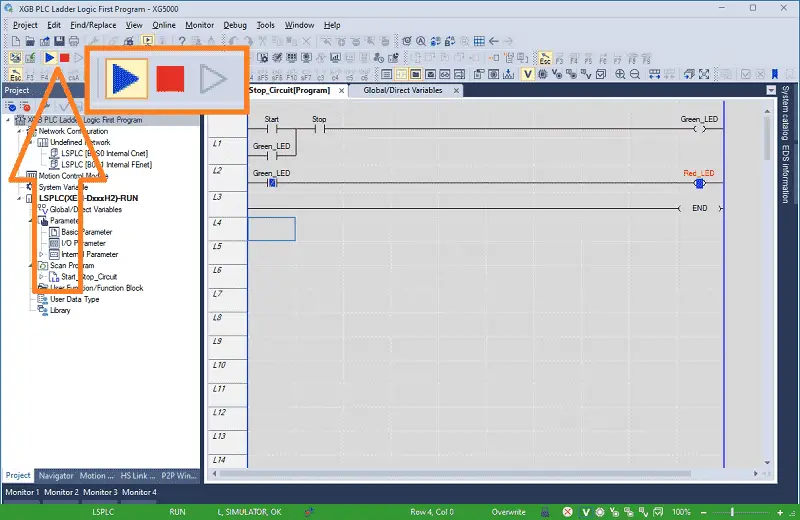
The PLC simulator will be placed automatically in RUN mode. Our program is now being executed in the simulator. You can start and stop this scan of the program in the simulator by using the icons on the main menu.
Monitoring and Testing the Ladder Logic Diagram
We can use the PLC simulator’s monitoring and troubleshooting tools to observe the behavior of the ladder logic program. We can display the inputs and outputs we want to monitor using the monitoring windows.
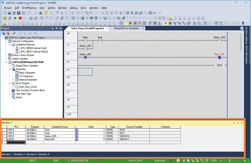
An easy way to add the variables to the monitor list is to select the ladder logic or variables. Then select Add from the main menu | Monitor | Add to variable monitor…
Your selected variable will now be displayed.
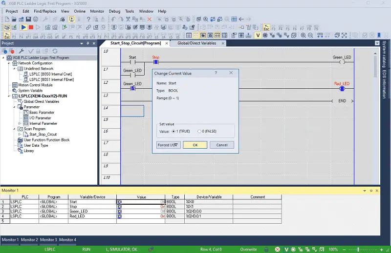
We can change the input variables and observe our program behavior by double-clicking on them.
See the video below for a demonstration of using the XG5000 PLC simulator with our Ladder Logic Diagram program.
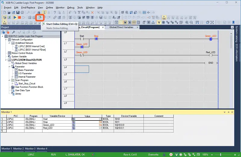
Adjustments can be made in the program using XG5000 when issues or errors are discovered. We can create and save the necessary changes to our program using the Online edit mode.
Using the PLC simulator in the XG5000 programming software for ladder logic is an effective way to test and debug PLC programs without physical hardware. It provides a safe and efficient environment for programmers to validate their logic and ensure proper operation before deploying it to real-world applications. By following the steps outlined above, you can harness the power of the PLC simulator to streamline your development process and deliver reliable PLC programs.
Download the Start Stop Circuit Sample Program and try it yourself. Let me know how you make out in the comments below.
Watch on YouTube: XGB PLC Simulator Ladder Logic Diagram
LS XGB PLC Additional Information:
LS XGB PLC – Series
– FAQ – Frequently Asked Questions
Product Cut Sheet (XEM-DN32H2 Unit Specifications)
LS PLC Technical Specifications
Manuals:
Interactive Guide
LS PLC User Manual
Other Documents:
PLC Installation Guide
Product Brochure
PLC Statement of Direction
Software and Support:
XG5000 / XG-PM PLC Programming Software
XEM PLC Firmware
Quick Start Procedures
XEM Pulse Servo Wiring Diagrams
Example Applications Directory
If you have any questions or need further information, please contact me.
Thank you,
Garry
If you’re like most of my readers, you’re committed to learning about technology. Numbering systems used in PLCs are not challenging to know and understand. We will walk through the numbering systems used in PLCs. This includes Bits, Decimals, Hexadecimal, ASCII, and Floating Points.
To get this free article, subscribe to my free email newsletter.
Use the information to inform other people how numbering systems work. Sign up now.

The ‘Robust Data Logging for Free’ eBook is also available for free download. The link is included when you subscribe to ACC Automation.