We will now look at online editing and the powerful debug mode of our BRX Do-More controller. Our first program for the BRX Do-More PLC involved a start-stop jog circuit. We will now use the Do-More Designer Software to modify this program while the PLC is scanning the logic. This is referred to as online programming or online editing. As a system integrator, this ability can prove very useful to you in the field when commissioning your automation system.
We will also be using the special Debug Mode of the software to monitor the ladder logic status and bits on a scan by scan basis. Forcing the inputs and outputs, we will control the execution of the PLC scan. This is a great feature of the Do-More Designer software.
Here is a link explaining the logic behind our circuit.
How to Make a Start Stop Jog Circuit in a PLC
Let’s get started.
Previously in this BRX Do-More series PLC, we have discussed:
System Hardware – Video
Unboxing – Video
Installing the Software – Video
Establishing Communication – Video
Firmware Update – Video
Numbering Systems and Addressing – Video
First Program – Video
Monitoring and Testing the Program – Video
Online Editing – BRX Do-More
Online editing is when you have a program that is being executed and additional or modified lines of the program are then inserted into the running program. This is accomplished by pausing the scan temporarily, inserting the code, and then resuming the scan of the controller.
We will modify our existing start stop jog circuit. Connect to the BRX Do-More PLC (or Simulator).
Select the Edit Mode symbol or Ctrl+E. You can also get to this by the main menu | Edit | Edit Mode.
Like the offline programming that we did before when in edit mode the edit mode icon in the menu is highlighted.
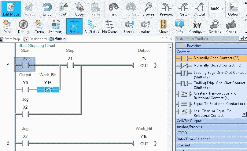
The instruction toolbox is also displayed in the edit mode.
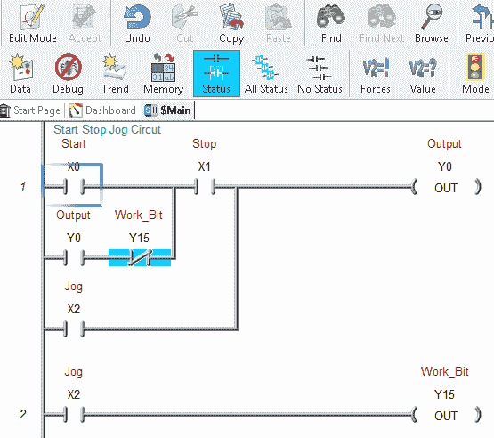
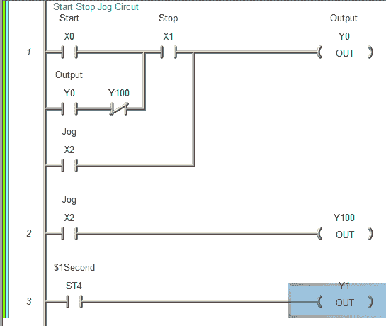
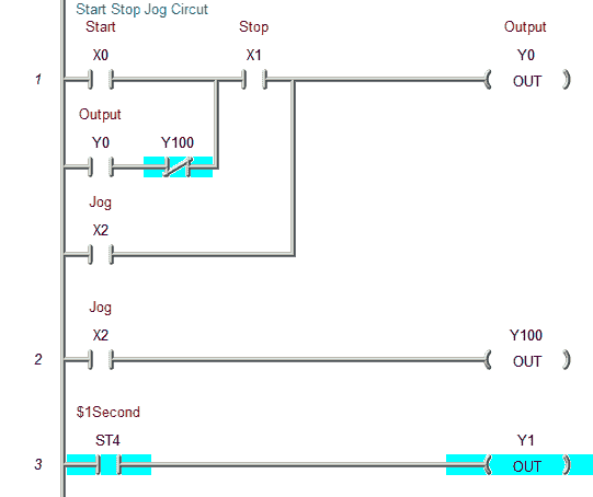
We can now start to modify our ladder logic. Change the normally closed contact from Y15 to Y100.
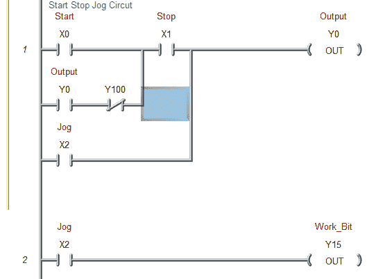
You will notice the yellow stripe along the left-hand side. This indicates that we have not accepted the changes yet. We will continue our changes by changing the output Y15 to Y100.
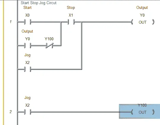
You now see the yellow left strip on both of our rungs. Let’s add an additional line to our program on rung 3. We will use the system bit ST4 (1-second clock pulse bit) to turn on the second output location Y1.
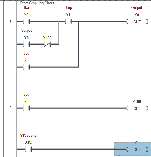
These are all of the modifications that we want in our program for now. Just like the offline editing we now need to Accept the rungs.
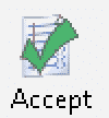
Hit the accept icon in the menu or F8. You can also use the main menu | Edit | Accept.
Once the rungs are accepted then the yellow strip is replaced by a blue and green strip.
The green strip means that the program has not been saved yet to disk. Select save like we did before and the green strip will now be removed leaving only the blue.
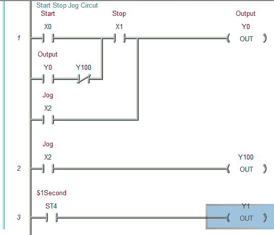
The blue strip means that the disk program and the PLC program are different. We must write the program to the PLC.
You can select the Write PLC icon in the menu or Shift+F9. You can also use the main menu | File | Write Project to PLC.
The Download Project to PLC window will now appear.
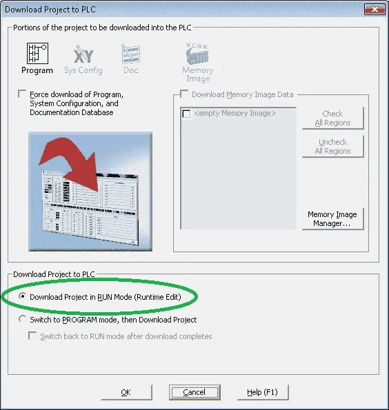
Select Download Project in RUN Mode (Runtime Edit)
Hit OK
Our modified program is now running in the PLC. You can see the monitored status of the logic.
Debug Mode – BRX Do-More

The debug mode will allow us to pause and control the scan of the PLC. It will also allow us to suspend tasks and programs. This can prove very helpful in troubleshooting systems.
Call up the debug view by selecting the debug mode icon in the menu. You can also use the main menu | Debug | Debug View.
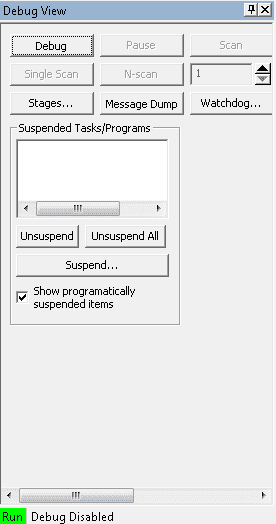
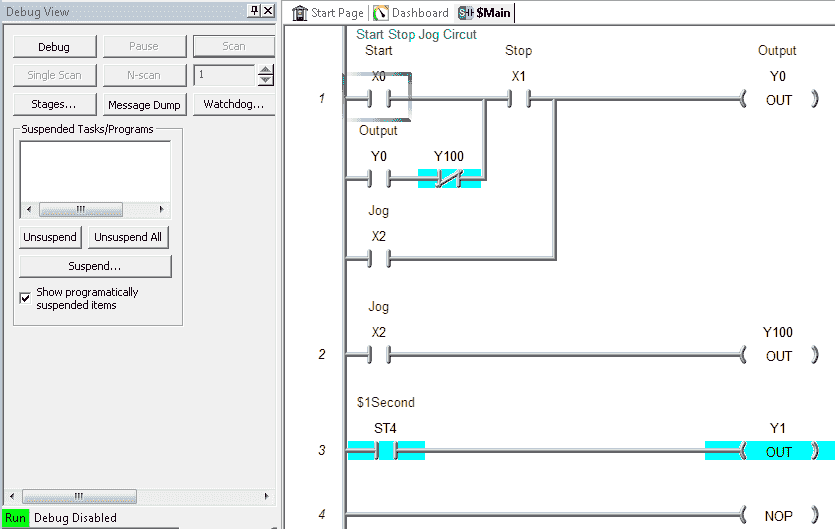
The debug view window will appear as a default on the left side of your screen with the Launchpad and Project Browser. The bottom of the debug view window will show you the status. In our case, the PLC is in run mode and the debug is disabled.
To enable the debug select the Debug button at the top of the debug view window.
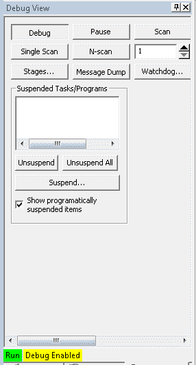
Our debug is now enabled and the menu buttons are now active.
Pause – This button will stop the scan of the PLC. When active the button will be outlined.
Scan – This button will resume the scan after the pause. When active the button will be outlined.
Single Scan – This button will release the pause for one scan.
N-Scan – This button will release the pause for the number of scans you specify to the right of the button.
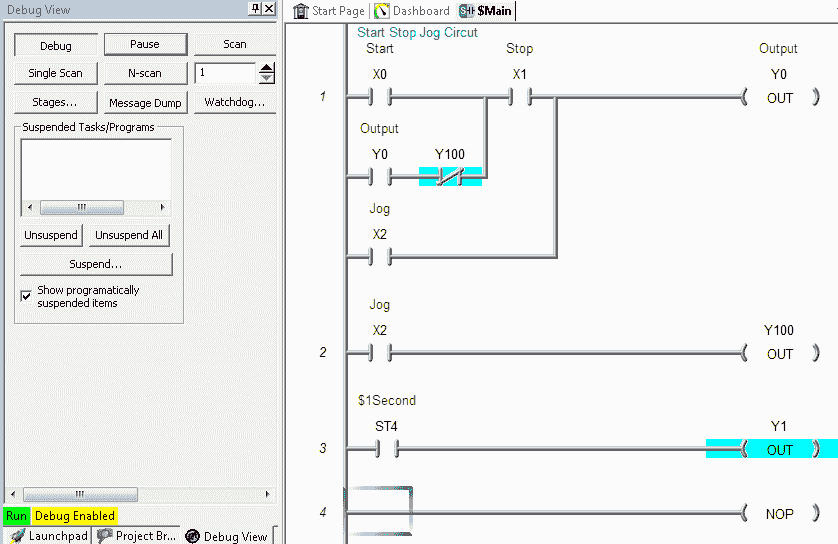
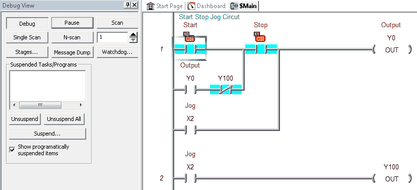
When paused, the outputs will remain in the last state before the pause. In our case, the output Y1 is on (1). Inputs during the pause will still turn on or off as indicated on the ladder but the instructions will not be executed.
Let’s now force the start (X0) and stop (X1) in our program.
We can now hit the single scan button on our debug view.
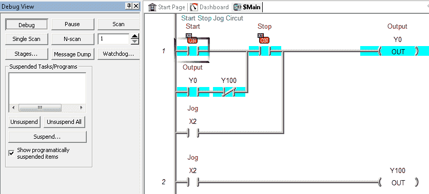
This turned on output Y0 in our circuit.
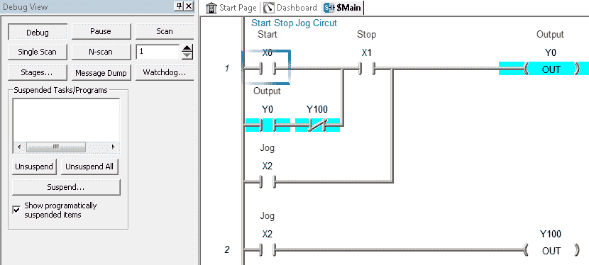
Un-forcing the start (X0) and stop (X1), our output remains on because the scan is still stopped.
We can now hit the Scan button to resume the scanning of our program. Hitting the debug button will disable the debug mode.
The X in the top right of the Debug View window can be used to close the window.
Controlling the scan of the program is an interesting and powerful way to troubleshoot the PLC.
You can watch the video below to see how you can change the logic of the PLC when it is in run mode and use the debug mode on the BRX Do-More Series PLC.
BRX Do-More Series PLC from Automation Direct – Power to deliver
Overview Link (Configure and purchase a system)
Manuals and Product Inserts (Installation and Setup Instruction)
Do-More Designer Software v2.0.3 (Free Download Link) – The software will contain all of the instruction sets and help files for the BRX Do-More Series PLC.
Next time we will look at timers in the BRX Do-More PLC.
Watch on YouTube: BRX Do-More PLC Online Editing and Debug Mode
If you have any questions or need further information please contact me.
Thank you,
Garry
If you’re like most of my readers, you’re committed to learning about technology. Numbering systems used in PLC’s are not difficult to learn and understand. We will walk through the numbering systems used in PLCs. This includes Bits, Decimal, Hexadecimal, ASCII, and Floating Point.
To get this free article, subscribe to my free email newsletter.
Use the information to inform other people how numbering systems work. Sign up now.

The ‘Robust Data Logging for Free’ eBook is also available as a free download. The link is included when you subscribe to ACC Automation.