We will now look at the C-More panel settings for communication to the PLC. The C-More EA9 HMI (Human Machine Interface) Series Panel will communicate to the PLC directly through the tag database that we discovered in our first program. We were able to read and write individual bits in the PLC.
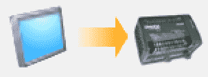
Panel to PLC communications is used to write information into the PLC; like current screen number displayed, good communications, pop-up keyboard, and current language number used in the HMI.
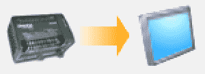
PLC to Panel communications is used by the PLC to control the HMI. Switch to screen number, beep, increment and decrement the Clock by one hour, clear alarm history, clear alarm count, start screen saver and select language are the items you can control in the HMI.
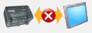
PLC Error is used to communicate internally in the HMI the PLC error state and PLC error code value.
We will be setting up and testing our PLC to Panel and Panel to PLC communications on our EA9 C-More. Let’s get started.
Previously in this C-More EA9 HMI Panel series, we have done the following:
System Hardware
– Unboxing and Review Video
– Powering the Unit Video
Installing the Software – Video
System Setup Screens – Video
First Program
– Establishing Communication and Updating Firmware Video
– First Program Video
Adding the Second Page
In our first program, we had only one screen. Let’s now add an additional screen to our HMI program.
Under the Navigation window on the Screen tab, you will see the icon for a new screen.
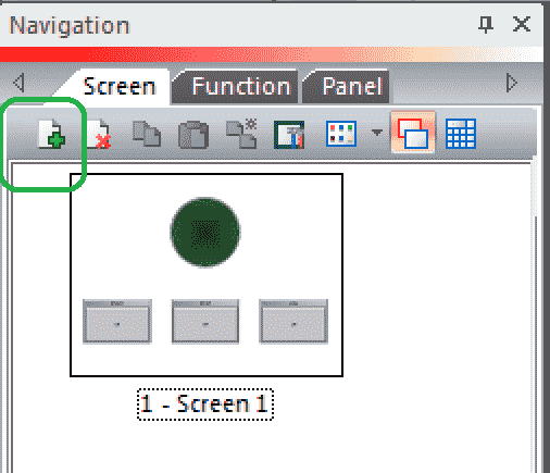
You will also see the icons for Delete, Copy, Paste, and Duplicate Screens.
You can also use the main menu Screen | New Screen … or Ctrl + N from the keyboard.
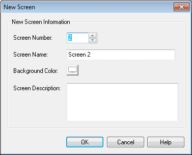
We will leave the default name as Screen 2. Hit OK.

Our new screen is added to our navigation window and our work area now shows our new Screen 2.
C-More Programming Software – Windows
You will notice on the screen five different windows that can be displayed, pinned or closed. Closing or pinning these screens will help you to make the work area larger.
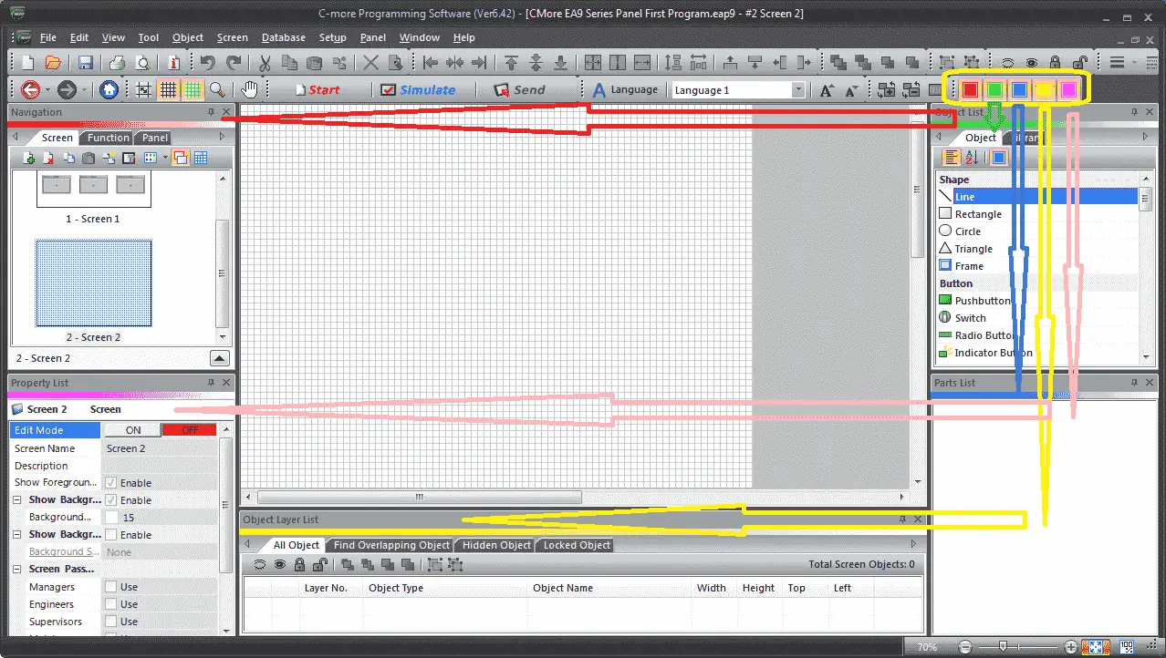
Each of the five coloured square icons represents a different window.
Navigation – Red
Object List – Green
Parts List – Blue
Object Layer List – Yellow
Property List – Pink
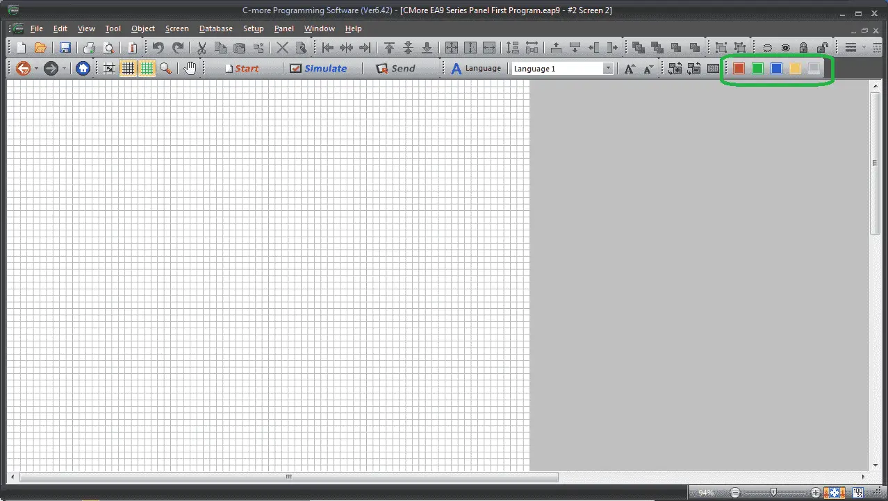
Here is the software with all of the windows turned off.
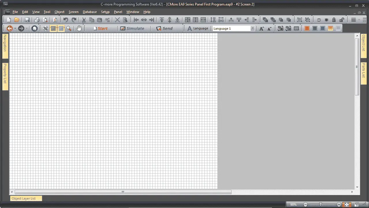
Here is the software with all of the windows pinned.
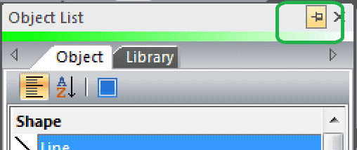
You click the pin in the window to toggle it. The pin horizontal means that the window is pinned. The pin vertical means that the window is not pinned.
C-More Panel to PLC Settings
In the navigation window under the function tab select PLC <->Panel.
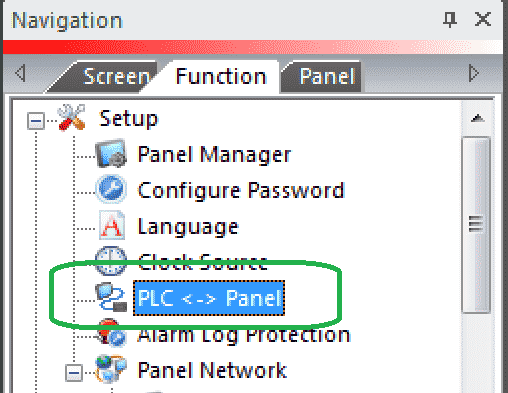
You can also use the main menu | Setup | PLC <-> Panel…
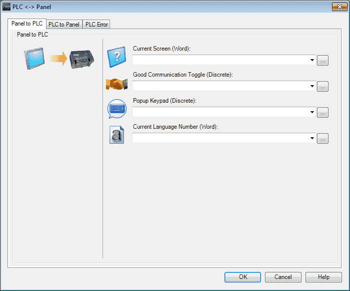
You will notice our three tabs along the top of the PLC <-> Panel window. The first one is the Panel to PLC. This is used to send the HMI panel information to the PLC.
Current Screen – Writes the Screen Number that the Panel is currently displaying into the PLC Address associated with the Tag. We will use MHR100 as the address in our Do-More PLC using Modbus TCP.
Good Communication Toggle – Used to confirm a good connection between the Panel and the PLC. The Tag toggles On to OFF on a 5-second interval. We will use MC100 as a bit in the PLC.
Popup Keypad – Used to indicate to the PLC when a Popup Keypad is displayed. (ON = Keypad Active). MC101 will be used as the tag.
Current Language Number – Writes the Number of the Language currently being displayed on the Panel. Refer to the Language settings under the Setup Menu. We will use MHR101 as the tag.
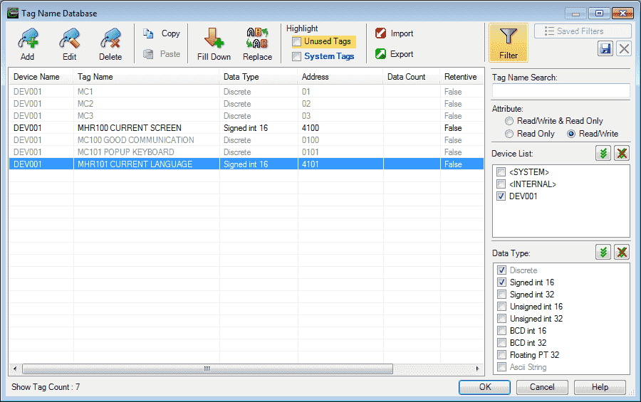
Here are the four tags that we have used for the panel to PLC window.
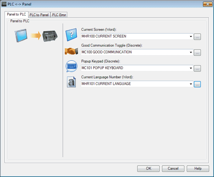
Our panel to plc information is now complete. You can watch the video below to see this in action.
C-More PLC to Panel Settings
Select the PLC to Panel tab on the PLC <-> Panel window.
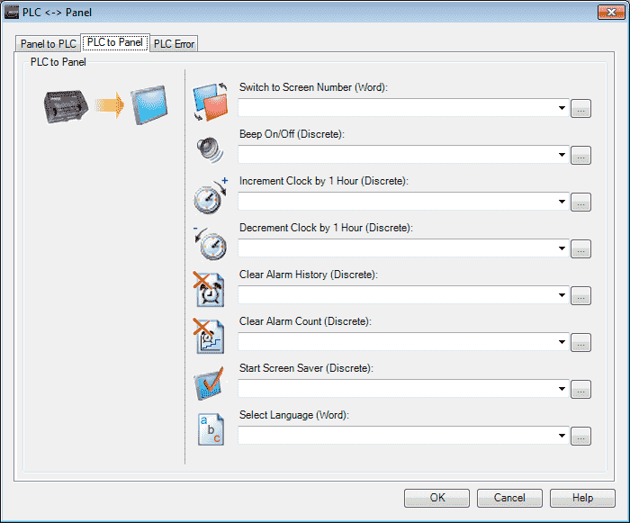
The PLC to Panel configuration is used to send PLC information to the Panel. This will give some control to the PLC.
Switch to Screen Number – Switches the displayed screen of the Panel to the Number in the associated PLC Address. Writes the Screen Number that the Panel is currently displaying into the PLC Address associated with the Tag. When the value changes, it is executed only once. If the value in the Tag does not correspond to an existing Screen Number, it is ignored without showing Error. If you load a “0” (usually with a PLC Tag) into the Switch to Screen Tag, the Panel will go to the last Screen that was displayed. MHR102 tag will be used.
Beep On/Off – Allows the PLC to turn On and Off the panel Beep. The Beep stays on until the bit is turned off. MC102 tag will be used.
Increment Clock by 1 Hour – Used by the PLC to adjust the Panel clock. Each OFF to ON transition increments the internal clock by one hour. This function is helpful for adjusting the Panel for daylight savings time.
Decrement Clock by 1 Hour – Used by the PLC to adjust the Panel clock. Each OFF to ON transition decrements the internal clock by one hour. This function is helpful for adjusting the Panel for daylight savings time.
Clear Alarm History – Used by the PLC to clear the Alarm History stored in the Panel. Each OFF to ON transition clears the history.
Clear Alarm Count – Used by the PLC to clear the Alarm Count stored in the Panel. Each OFF to ON transition clears the count.
Start Screen Saver – The backlight turns OFF when the Start Screen Save tag changes from OFF to ON.
The panel backlight will turn ON again for the following conditions:
– When the panel touchscreen is touched.
– When the screen is clicked in a Remote Access session.
– When an Alarm Action in the Event Manager occurs. (Only when the Display setting of the Alarm Action is checked).
– When there is a Screen Change by the PLC.
– When an Error such as a Communication Error occurs.
Select Language – Used by the PLC to change the present Language being displayed on the Panel. Refer to the Language Settings under the Setup Menu. When the value changes, it is executed only once. If the value in the Tag is out of the range 1 to 9, it is ignored.
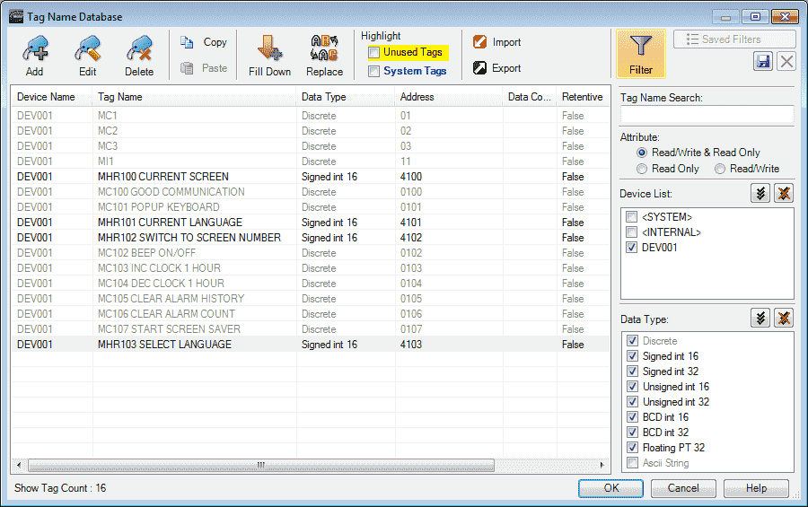
Here are the tags that have been set in the tag database.
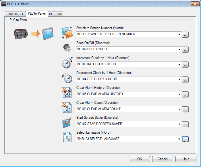
Our PLC to Panel information is now complete. You can watch the video below to see this in action.
C-More PLC Error
The PLC Error configuration is used to communicate PLC Errors to the Panel. This feature can be used to display PLC Errors in other objects on the Panel such as indicator lights, dynamic bitmaps numeric displays, dynamic text displays, and multi-state indicators.
Select the PLC Error tab on the PLC <-> Panel window.
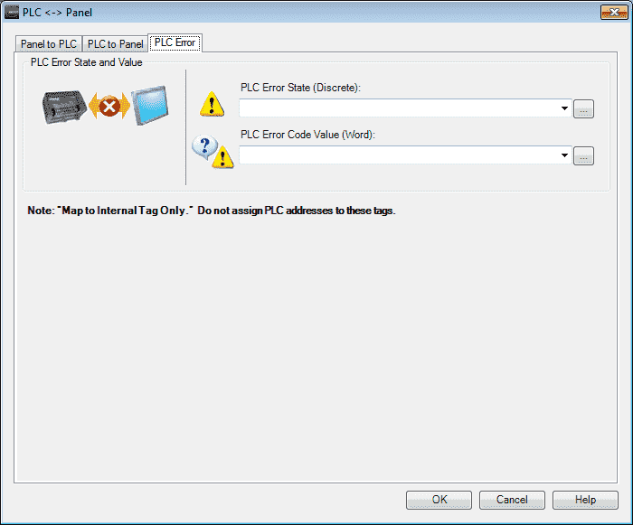
The tags on this tab are only internal. Tags will be set in the C-More panel if an error occurs.
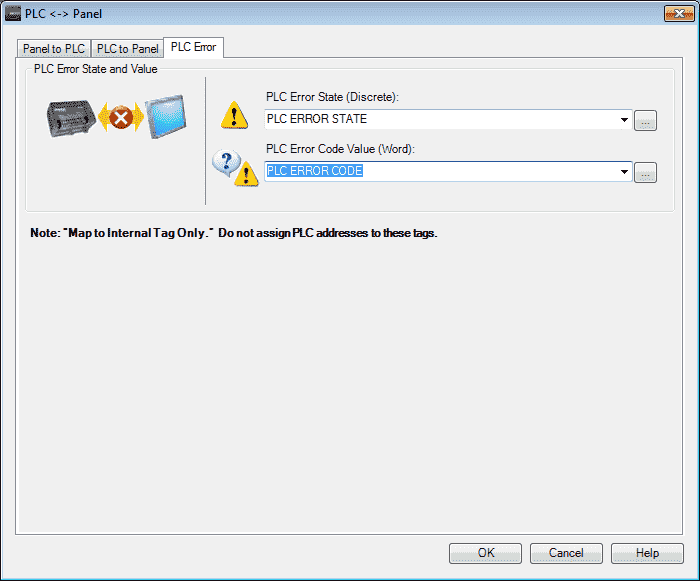
We will set up a discrete internal tag called PLC ERROR STATE.
PLC ERROR CODE will be the tag that will display the error number. This is a 16 bit signed word.
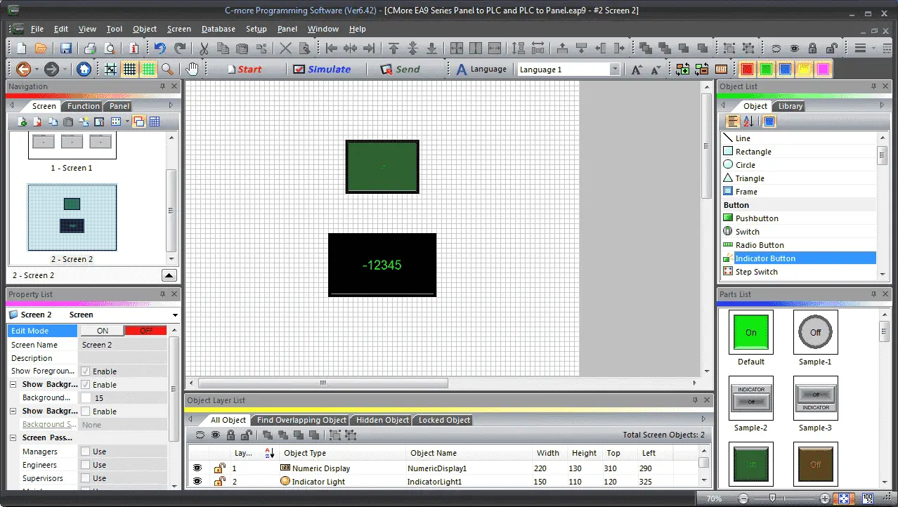
On screen 2 we will put an indication button with the PLC ERROR STATE. We will also put a numeric display with the PLC ERROR CODE.
The following URL will give you the error codes associated with the C-More HMI Panel.
Error Codes and Related Topics
We can now use the Do-More Simulator and test our HMI panel.
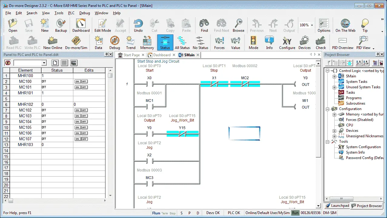
We can call up a Data View window to test our parameters.
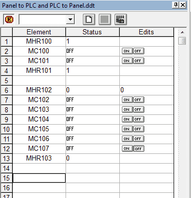
Watch the video below to see the PLC to Panel and Panel to PLC settings in action in our C-More EA9 HMI Panel.
Download the PLC and C-More Panel Programs here.
C-More EA9 Panels from Automation Direct
https://www.automationdirect.com/c-more/home
C-More – Graphic Panel (EA9 Series) User Manual and Quick Start Guides
https://cdn.automationdirect.com/static/manuals/ea9userm/ea9userm.html
EA9-T10CL C-More Specifications
https://cdn.automationdirect.com/static/specs/ea9t10cl.pdf
C-More EA9 Programming Software (Current Version V6.42)
https://support.automationdirect.com/products/cmore.html
This software will enable you to program all of the C-More EA9 HMI units. It includes a simulator for your application.
Next time we will look at a Common Screen Menu that we can set in the C-More HMI Panel.
Watch on YouTube: C-More EA9 HMI Series Panel to PLC and PLC to Panel Settings
If you have any questions or need further information please contact me.
Thank you,
Garry
If you’re like most of my readers, you’re committed to learning about technology. Numbering systems used in PLC’s are not difficult to learn and understand. We will walk through the numbering systems used in PLCs. This includes Bits, Decimal, Hexadecimal, ASCII and Floating Point.
To get this free article, subscribe to my free email newsletter.
Use the information to inform other people how numbering systems work. Sign up now.
The ‘Robust Data Logging for Free’ eBook is also available as a free download. The link is included when you subscribe to ACC Automation.


