We will now put our first program into the C-More EA9 HMI Panel using the C-More programming software. The Do-More Designer Simulator will be used with a modified Start Stop Jog Circuit so we can use our C-More HMI screen to monitor the output as well as control the inputs on the PLC.
Communications will be established to our C-More EA9-T10CL unit and the firmware will be updated. We will then develop our control for our PLC ladder logic circuit.
The PLC logic for our circuit can be found on our post: How to Make a Start / Stop / Jog Circuit in a PLC. The YouTube video can be seen here.
Our C-More EA9 HMI Panel will be communicating to the PLC simulator via Ethernet with the Modbus TCP protocol. Let’s get started.
Previously in this C-More EA9 HMI Panel series, we have done the following:
System Hardware
– Unboxing and Review Video
– Powering the Unit Video
Installing the Software – Video
System Setup Screens – Video
C-More First Program Establish Communication
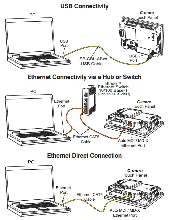
Plug the USB cable into the back of the C-More HMI and the computer that you have installed the C-More programming software. (The USB port is only used for programming.) Also, connect the Ethernet port to the Ethernet Switch. This port can be used for programming or communication to the PLC. In our case, we will be using this to communicate to our Do-More Designer PLC Simulator.
Start the C-More Programming Software that we installed in our previous post. When the “Start a Project” window appears, hit the Cancel button to close the window. This window will start up as a default every time you start the software.
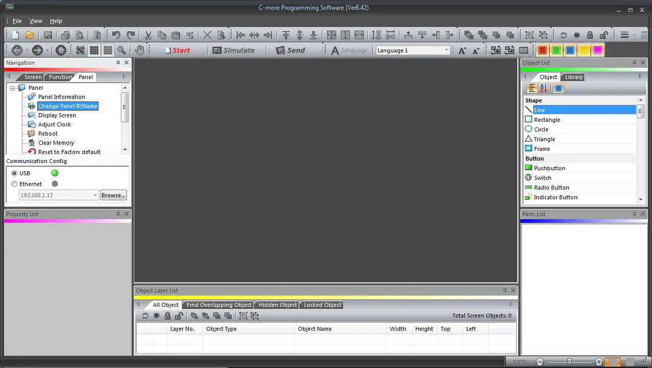
Under the Panel tab in the navigation area of the screen, you will see the Communication Config. In the picture above it is set for USB communication. The green indication lamp means that this connection is active and functional.
Select the Ethernet option under the Communication Config.
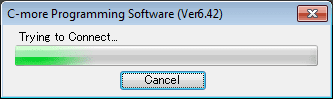
The software will attempt to connect to the C-More HMI screen through the Ethernet port.
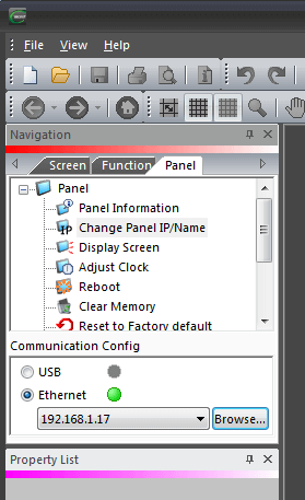
We will now see that the Ethernet connection is selected and we have a good connection to the C-More HMI.
Select the Browse… button next to the IP address of the C-More HMI panel.
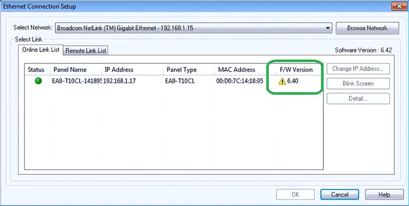
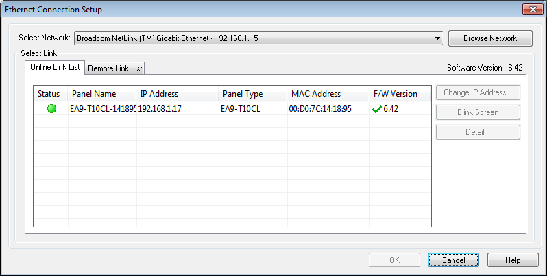
Our communication specifications will now be shown. You can see that the network selected is through our Broadcom Netlink ™ Gigabit Ethernet card on our computer. It has an IP address of 192.168.1.15.
Our panel Name is EA9-T10CL-141895
IP Address – 192.168.1.17
Panel Type – EA9-T10CL
MAC Address – 00:D0:7C:14:18:95 – Physical address
Firmware Version – 6.40
Note that we have a warning sign next to our F/W Version. This means that we have an update. The newest firmware version is 6.42.
Hit the Cancel button on the Ethernet Connection Setup window to close.
C-More Firmware Update
Start a new project by selecting the red Start icon on the main menu.
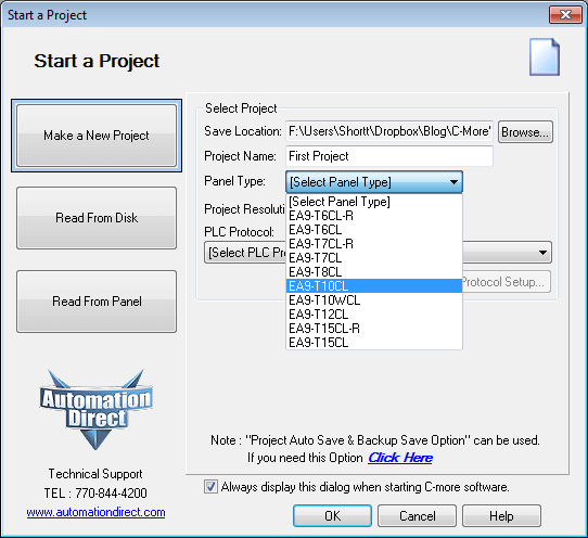
We will give the project the name “First Program”. Select the EA9-T10CL panel type that we discovered above.
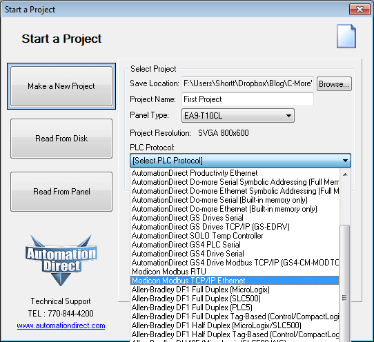
Under the PLC Protocol, select Modicon Modbus TCP/IP Ethernet. This is the protocol that our Do-More simulator will be using.
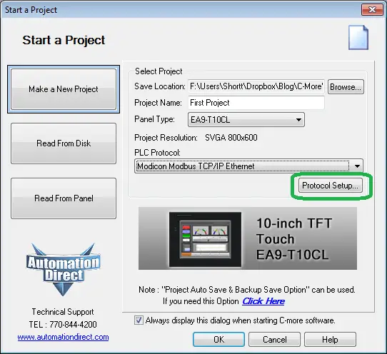
You will now see a graphical picture of the C-More HMI panel that we will be programming. Select the Protocol Setup… button.
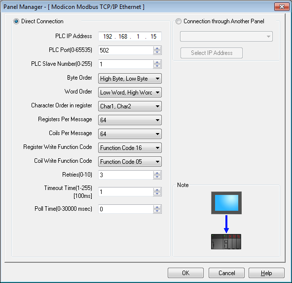
The Panel Manager (Modicon Modbus TCP/IP Ethernet) window will now be displayed. We will put in our PLC address which is the same as our computer IP address that we discovered above. (192.168.1.15) Hit the OK button to close the window.
Select the green Send icon on the main menu.
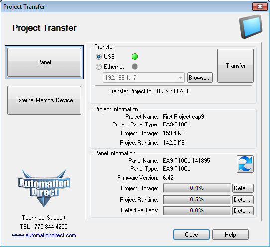
The Project Transfer window will now appear. We will use the USB cable. Select the Transfer button.
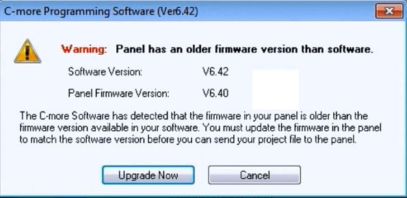
Notification will be given to you if the panel has an older firmware version than the programming software. Select Upgrade Now button.

A further message will be displayed before the update is started for the firmware. Press the OK button to continue.

Our firmware will now be updated to the latest version.
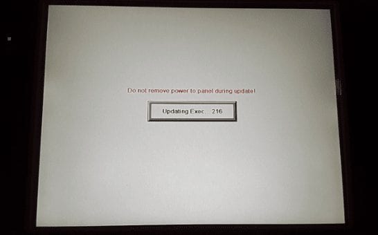
The C-More HMI panel will indicate that the software is being updated.
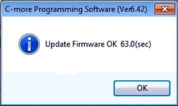
A message window will be shown when the firmware update has been completed. Our EA9-T10CL panel will then be rebooted.
We can then go back to the procedure above and verify that our new firmware version is in the C-More HMI.
Watch on YouTube: C-More EA9 HMI Series Panel Establishing Communication and Updating Firmware
C-More First Program – PLC Ladder Logic Sample
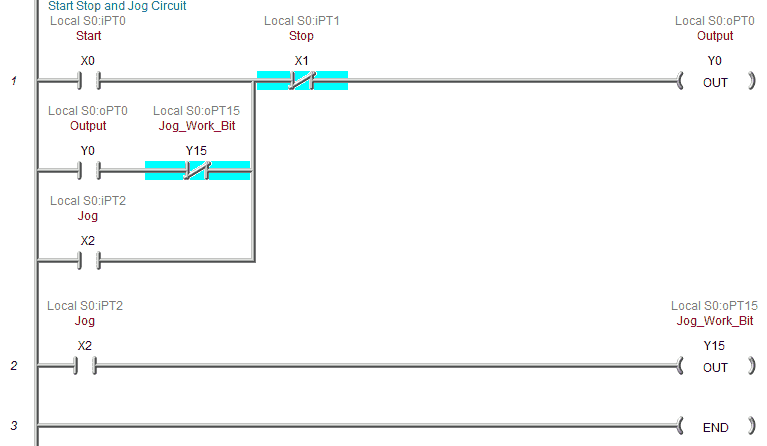
Here is our existing logic for our start-stop jog circuit.
We will be using discrete on/off inputs and output from the C-More EA9 HMI in parallel to our existing logic.
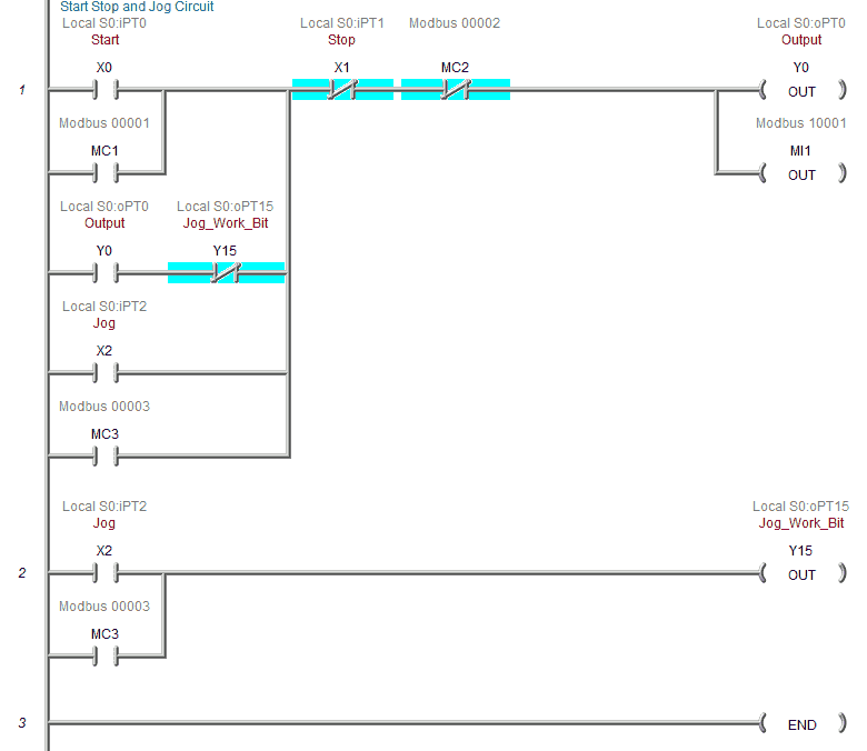
MC1 – Start input from the HMI
MC2 – Stop input from the HMI
MC3 – Jog input from the HMI
MI1 – Output indication from the HMI
The PLC system configuration can be seen by selecting the System Configuration under Tools in the Project Browser. This can also be reached under the main menu | PLC | System Configuration…
Under the heading Internal Ethernet Port Configuration, we will find the IP address and Net Mask for our connection. This can be changed if required. We will use the default for our simulation.
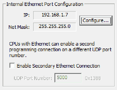
IP Address: 192.168.1.15
Under the heading Modbus/TCP Server Configuration you will see the following:
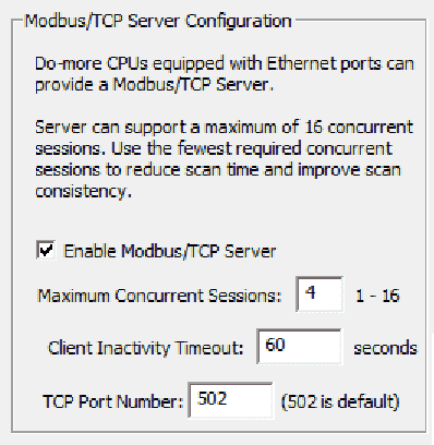
The Modbus/TCP server is enabled by default. Modbus TCP port number is 502 by default as well.
Note: Modbus Server and Modbus Slave are the same things. Modbus Client and Modbus Master are also the same things. You will come across serial communication that uses Modbus Master and Slave, and Ethernet communication that uses Modbus Client and Server. However, these names can be mixed up.
Do More Designer Simulator PLC – Modbus Address Map
The following table shows the Coil/Register numbers and the associated Do-More Simulated PLC address for Modbus.
| Coil/Register Numbers | Data Addresses | Type | Do-More PLC (BRX) | Table Name |
| 00001-09999 | 0000 to 270E | Read-Write | MC1 to MC1023 | Discrete Output Coils |
| 10001-19999 | 0000 to 270E | Read-Only | MI1 to MI1023 | Discrete Input Contacts |
| 30001-39999 | 0000 to 270E | Read-Only | MIR1 to MIR2047 | Analog Input Registers |
| 40001-49999 | 0000 to 270E | Read-Write | MHR1 to MHR2047 | Analog Output Holding Registers |
Note: The Do-More Series PLC uses the Modbus area to communicate. This is because having direct access to the digital I/O can be dangerous when connected via Ethernet to the internet. Data must move in and out of this area via the PLC program.
Programming the C-More HMI Screen
We made a program called First Program above and set up our communication information.
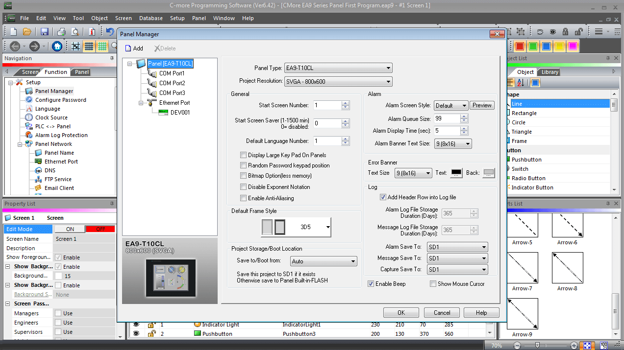
Under the Function tab in the Navigation window of the C-More software, you will see the Panel Manager. Double click this and the Panel Manager window will be displayed.
Select Ethernet Port (DEV001) under the Panel [EA9-T10CL].
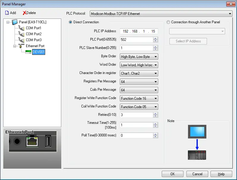
This window will confirm our PLC Protocol and settings to our PLC. Hit the OK button to return to the main programming area.
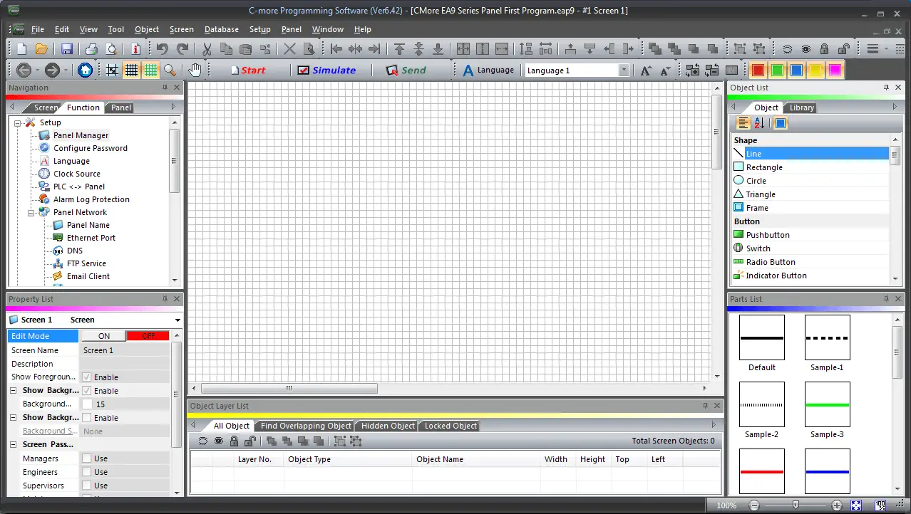
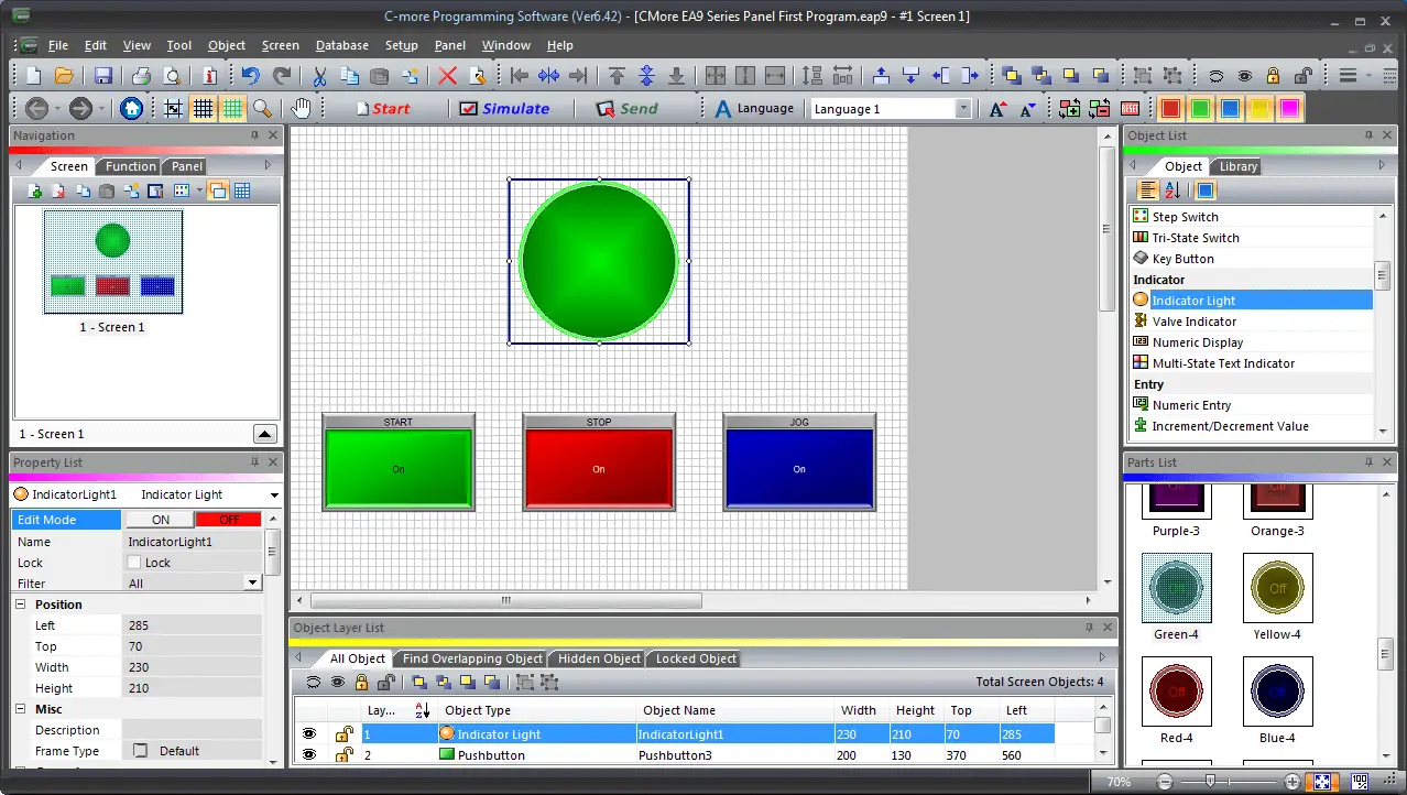
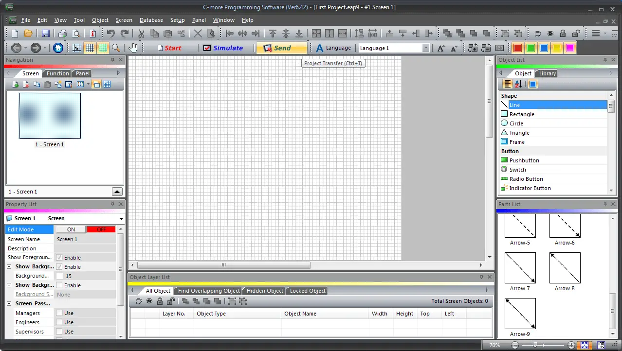
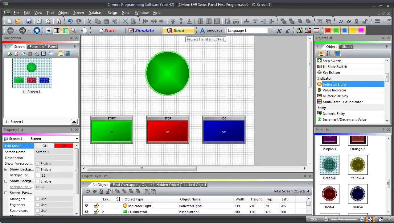
The white space in the middle of the screen is our work area. This represents the information of the screen selected on the left under Navigation (Screen).
Let’s change the work area zoom to ‘Fit to Screen’ from the default 100%.
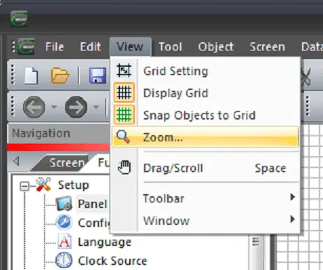
Select View | Zoom… from the main menu.
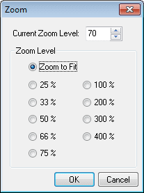
Select ‘Zoom to Fit’ from the radio buttons. Hit OK to close the zoom window.
Our work area now matches the view on our screen. We will be placing three pushbuttons and one indication light on the screen.
Adding our C-More Pushbuttons
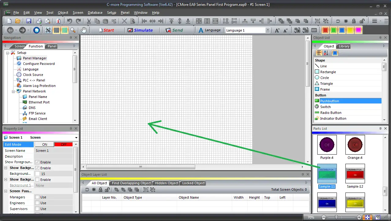
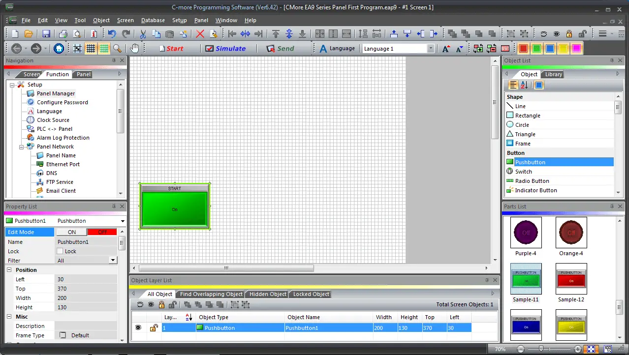
Under the Object List select Pushbutton under the heading Button. The parts list will show you all of the available pushbuttons that are available for you to use.
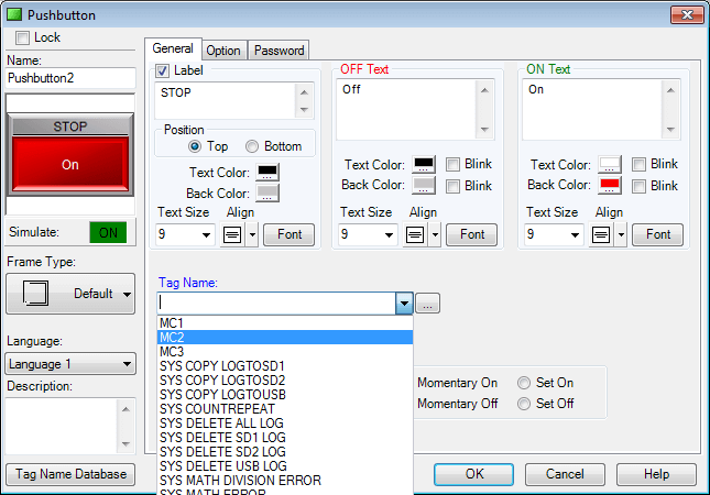
Select Sample-11 by clicking and dragging the selection to the work area. The following Pushbutton window will appear.
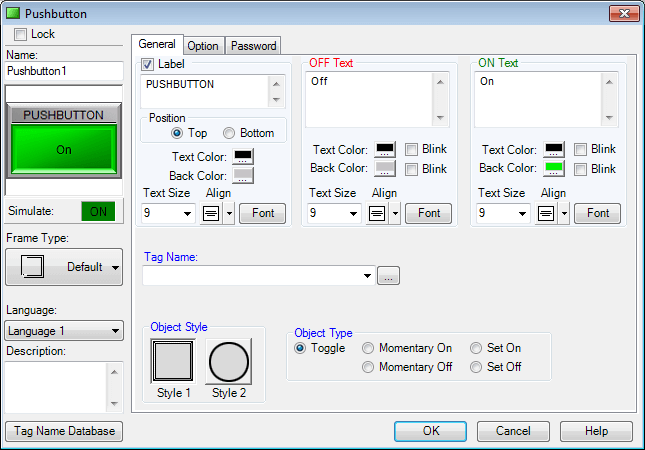
We can now change the information on the PB.
C-More Tag Name Database
A tag name is a name used in C-More HMI to allow communication of data from an object to a controller. (PLC) The tag name is commonly an abbreviated name that identifies a specific function. Each tag name has a set of user-specified parameters.
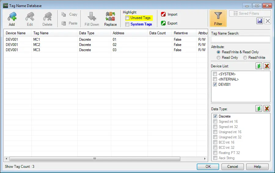
Near the Tag Name, select the three dots to call up the tag name database.
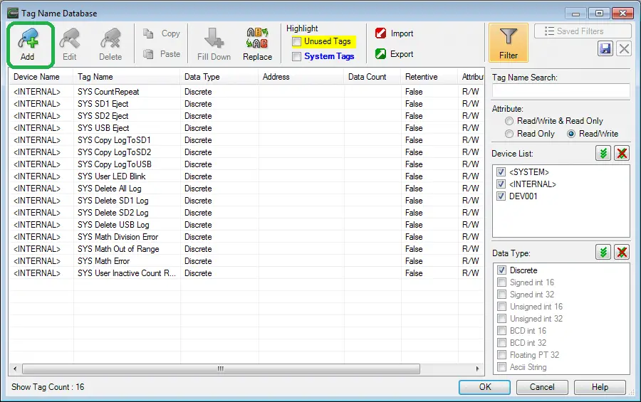
We can add additional tags by selecting the Add… button near the top of the Tag Name Database window.
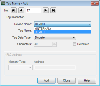
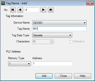
Select the following features of our tag.
Device Name – DEV001 – This is the Modbus TCP protocol out the Ethernet port that we selected on the start of a project window.
Tag Name – MC1 – This is the name that we want to call the tag.
Tag Data Type – Discrete – This means that it is an on/off, 1 or 0 type tag.
PLC Address
Memory Type – 0 – This means a discrete read or writes for Modbus
Address – 1 – This is the address for the Modbus tag. See above chart for all of the addresses in the Do-More PLC.
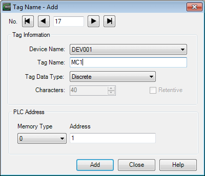
Hit ADD to add the new tag to the database.
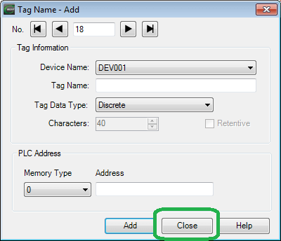
Our Tag Name – Add window will increment to the next available tag for us to fill out. We will hit the Close button.
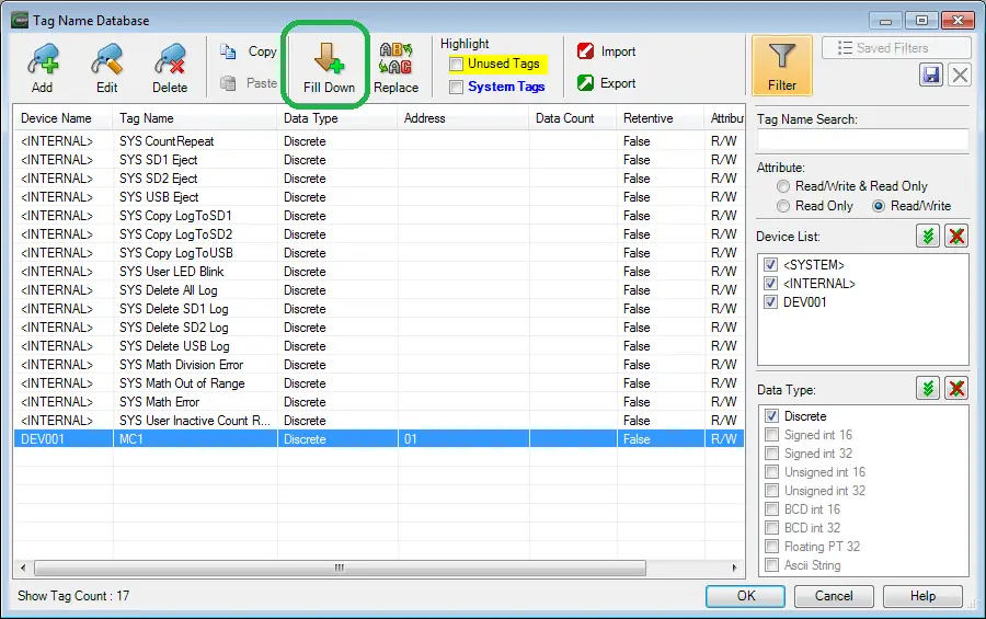
We can see our added tag in the list on the Tag Name Database. An additional and quick way to add tags is to use the Fill Down button on the Tag Name Database window.
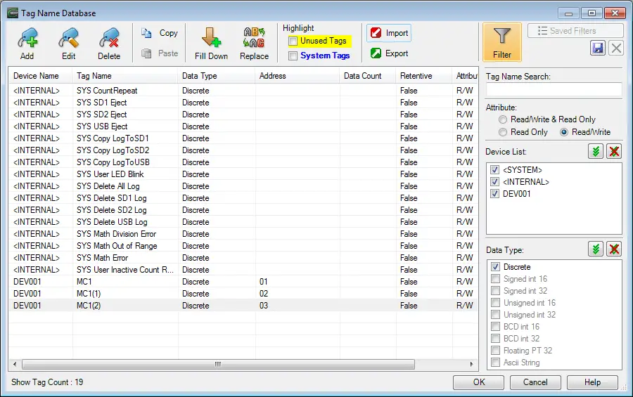
The tag will automatically increment the address for us. We can then just change the name of the tag by editing the tag.
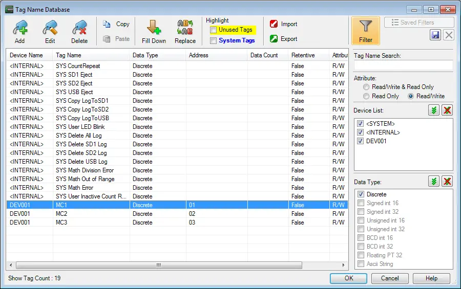
We have now completed all of our input tags to the PLC. Select the tag that we want and hit OK at the bottom of the Tag Name Database window.
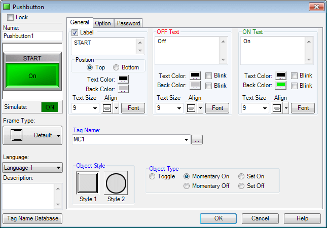
The following parameters will be set on our Pushbutton.
Label – START.
Object Type – Momentary On – This will simulate actual pushbuttons.
We will keep all of the other parameters as their default.
You can test what the button will look like by the Simulate under the picture of the button. This can be turned on and off.
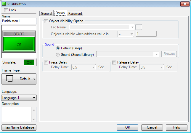
Hitting the Option tab will allow us to specify the visibility of this pushbutton, the default sound and the press/release delay time. We will leave these as their default values.
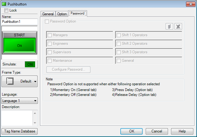
The Password tab is used for the passwords on our object (Pushbutton) that we are programming. In our case, the momentary button does not support a password option.
Hit OK at the bottom of the Tag Name Database window.
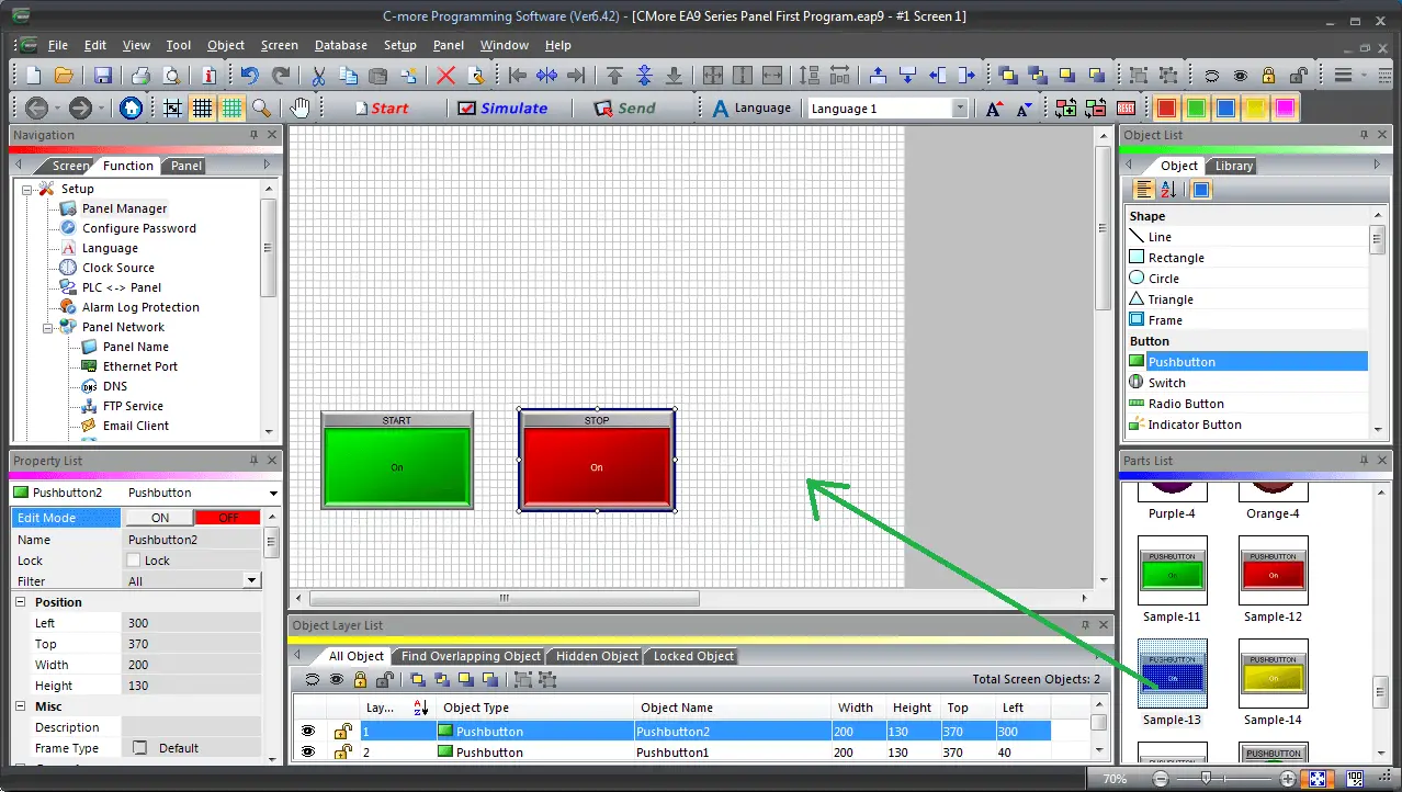
Position and size the pushbutton on the screen. Use the mouse to select the pushbutton object and click and drag to the new position and size.
Let’s repeat the above procedure for the Stop pushbutton.
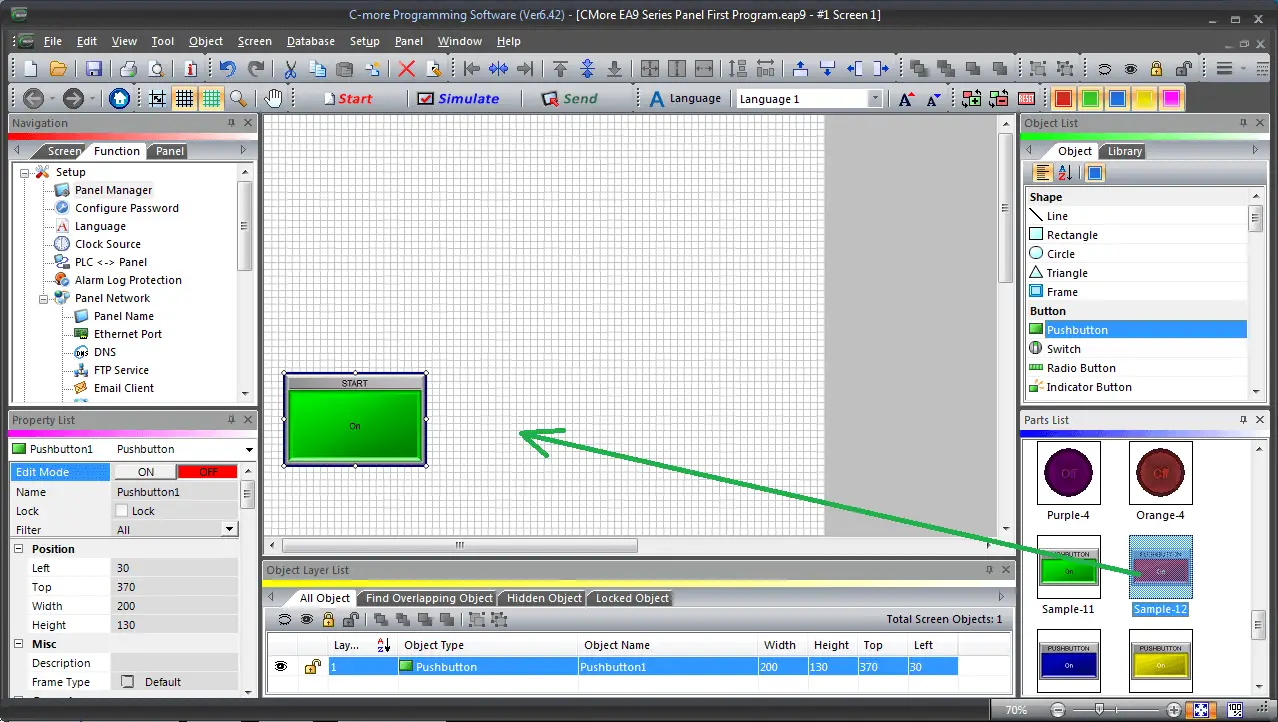
Click and drag Sample-12 from the parts list.
Our tag name will now be MC2 and the object type will be Momentary On.
Position and size the pushbutton on the screen. Use the mouse to select the pushbutton object and click and drag to the new position and size.
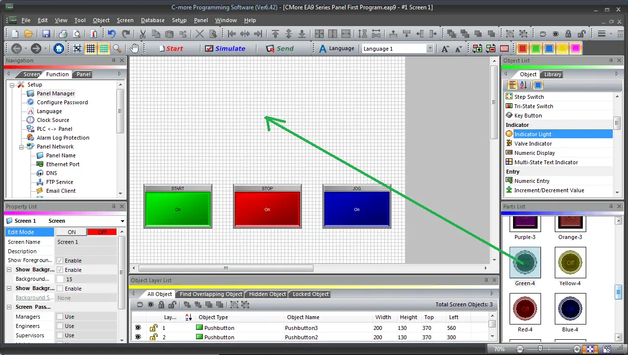
Add the Jog button to our screen by clicking and dragging Sample-13 from the parts list.
Our tag name will be MC3 and the object type will be Momentary On.

Click OK on the Pushbutton window.

Position and size the pushbutton on the screen. Use the mouse to select the pushbutton object and click and drag to the new position and size. Our three pushbuttons have now been programmed.
C-More Adding our Indication
Select Indicator Light under Indicator in the Object List. Drag the Green-4 under the parts list onto the work area.
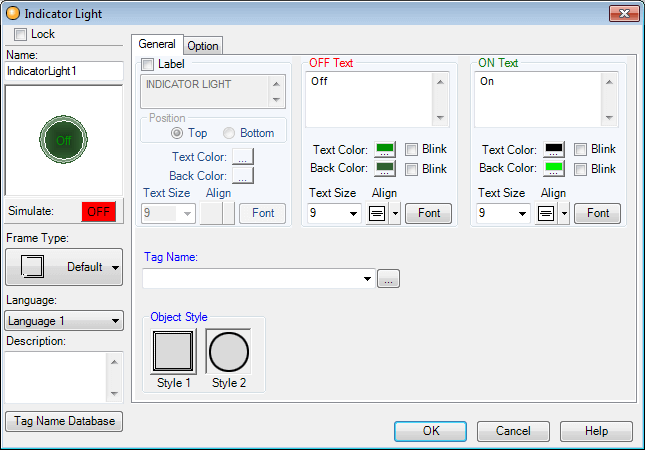
Select the Tag Name Database by hitting the three dots to the right of the selection.
Under the Device List, uncheck the AND tags. This will leave us with only the DEV001 tags displaying.
Select the Add… button on the Tag Name Database window.
We will add the indication tag MI1 – This will have the Modbus address of 10001.
Select Add and then Close to close the Tag Name Add window.
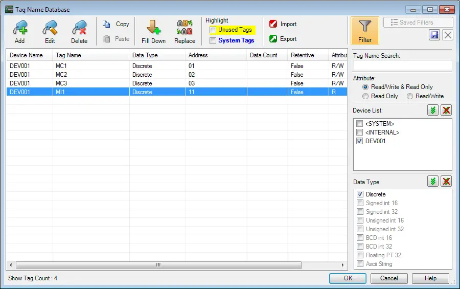
Highlight our new tag and select the OK button.
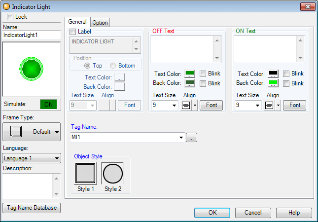
Our selection will be returned to our Indicator Light window under the Tag Name. Remove the Off and On text fields. Hit OK.
Position and size of our new indication lamp can be done now.
Save our C-More first program
Hit the save icon on the main menu or go to File | Save Project on the main menu. This will save our project to disk. Alternatively, you can use the keyboard shortcut of Ctrl + S to save the project.
Send Project to Panel
We can send the project to the panel in several different ways. You will see a button under the main menu that says “Send”. Under the main menu, you can select File | Project Transfer… The last way is to use the keyboard shortcut of Ctrl + T to send the project to the panel.
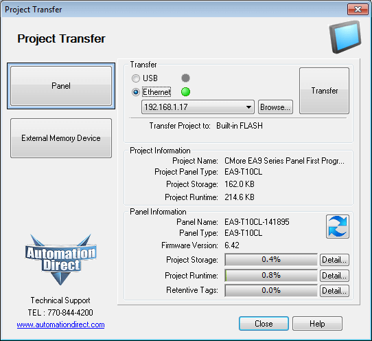
We can send the project by the serial communication port via the USB or through our Ethernet port. We will use the Ethernet port and then hit the Transfer button.
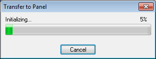
Our first C-More program will now be transferred to the C-More HMI panel.
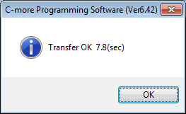
Hit OK after the transfer completion notification.
Testing our C-More first program
We can now use the Do-More Simulator and test our C-More HMI panel
Watch the video below to see the first program in our C-More EA9 HMI Panel.
Download the PLC and C-More Panel First Programs here.
C-More EA9 Panels from Automation Direct
https://www.automationdirect.com/c-more/home
C-More – Graphic Panel (EA9 Series) User Manual and Quick Start Guides
https://cdn.automationdirect.com/static/manuals/ea9userm/ea9userm.html
EA9-T10CL C-More Specifications
https://cdn.automationdirect.com/static/specs/ea9t10cl.pdf
C-More EA9 Programming Software (Current Version V6.42)
https://support.automationdirect.com/products/cmore.html
This software will enable you to program all of the C-More EA9 HMI units. It includes a simulator for your application.
Next time we will look at the Panel to PLC and PLC to Panel Settings of the C-More.
Watch on YouTube: C-More EA9 HMI Series Panel First Program
If you have any questions or need further information please contact me.
Thank you,
Garry
If you’re like most of my readers, you’re committed to learning about technology. Numbering systems used in PLC’s are not difficult to learn and understand. We will walk through the numbering systems used in PLCs. This includes Bits, Decimal, Hexadecimal, ASCII and Floating Point.
To get this free article, subscribe to my free email newsletter.
Use the information to inform other people how numbering systems work. Sign up now.

The ‘Robust Data Logging for Free’ eBook is also available as a free download. The link is included when you subscribe to ACC Automation.