Previously we put our first program (Video) into the C-More Micro HMI Panel using the C-More Micro programming software. The Do-More Designer Simulator was used with a modified Start Stop Jog Circuit so we can use our HMI screen to control the output as well as the inputs on the PLC. This communication was done via Ethernet with the Modbus TCP protocol.
We will now look at PLC to Panel and Panel to PLC communications. This will allow us to control the screen page number, beeper and back light of the panel from the PLC. We will also get notification of the same as well as key press information from the HMI panel. Let’s get started.
Previously in this C-More Micro HMI Panel series we have done the following:
System Hardware – Video
Installing the Software – Video
– Update Automation Direct Software C-More Micro HMI Video
System Setup Screens – Video
First Program – Video
PLC Communication – Modbus TCP
Do More Designer Simulator PLC – Modbus Address Map
The following table shows the Coil/Register numbers and the associated Do-More Simulated PLC address for Modbus.
| Coil/Register Numbers | Data Addresses | Type | Do-More PLC (BRX) | Table Name |
| 00001-09999 | 0000 to 270E | Read-Write | MC1 to MC1023 | Discrete Output Coils |
| 10001-19999 | 0000 to 270E | Read-Only | MI1 to MI1023 | Discrete Input Contacts |
| 30001-39999 | 0000 to 270E | Read-Only | MIR1 to MIR2047 | Analog Input Registers |
| 40001-49999 | 0000 to 270E | Read-Write | MHR1 to MHR2047 | Analog Output Holding Registers |
Note: The Do-More Series PLC uses the Modbus area to communicate. This is because having direct access to the digital I/O can be dangerous when connected via Ethernet to the internet. Data must move in and out of this area via the PLC program.
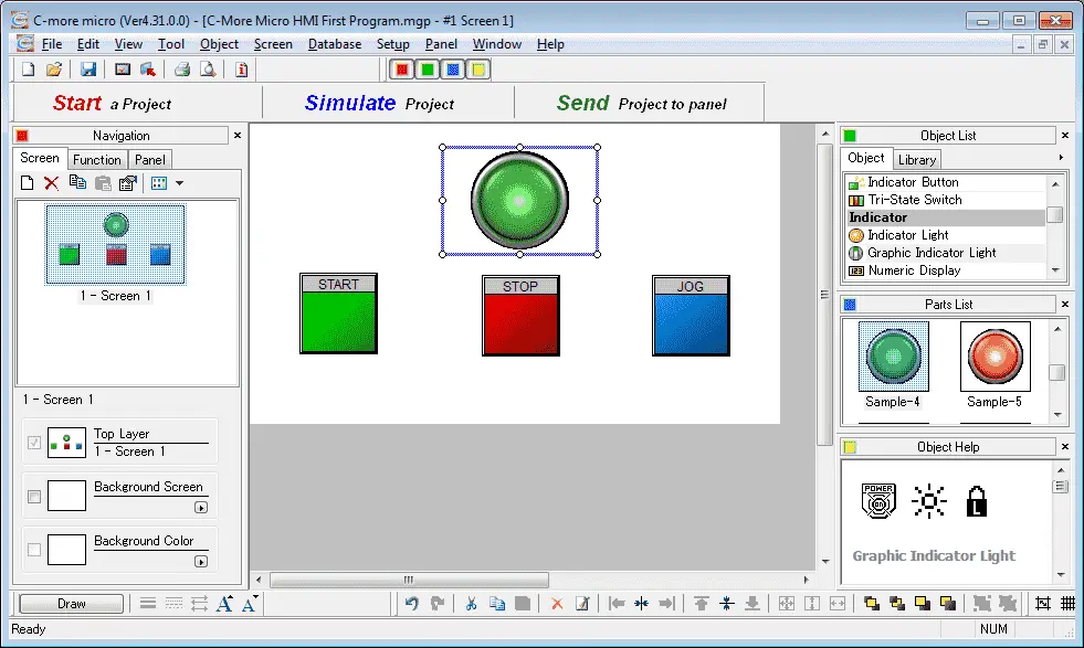
We will start by adding a second screen to our existing C-More Micro program that we created last time. Start the C-More Micro software and call up our existing program. Currently, we have only one screen programmed.
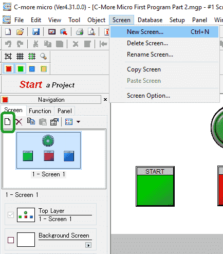
To add a screen, select Screen | New Screen.. from the main menu. You can also select the new screen icon located in the Navigation panel. The quick select key is Ctrl + N.
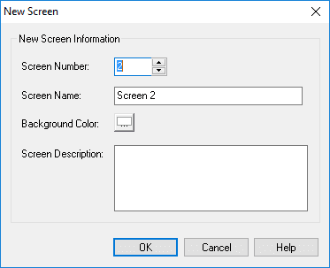
In our example, we will use the default screen name of Screen 2. A screen description can be added to document the purpose of each screen. Select OK.
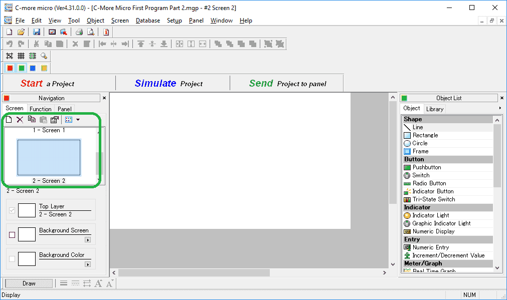
The icons under the navigation panel is helpful for adding, deleting, properties, etc. As you move your mouse over the icons descriptions will tell you what each one is about.
PLC to Panel / Panel to PLC – C-More Micro First Program
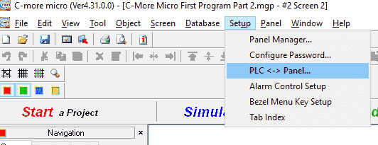
Call the Panel <-> PLC window by selecting Setup | PLC < – > Panel from the main menu.
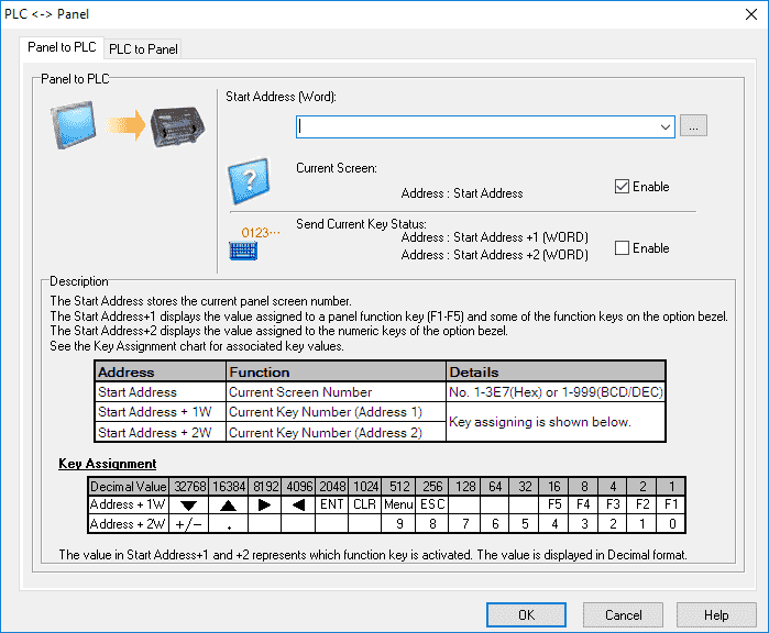
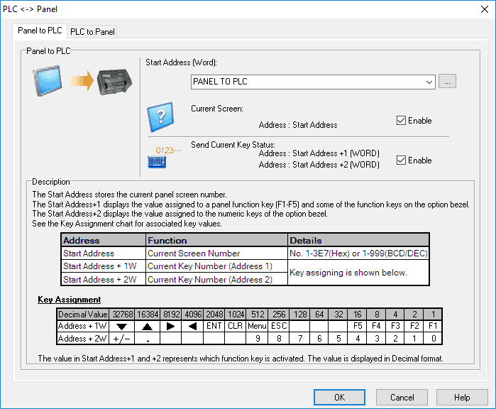
The default tab of Panel to PLC will be displayed as the default. This tab will allow the C-More Micro HMI Panel to communicate to the PLC the current screen number and current key number.
The Current Screen is automatically enabled. We will also enable the Send Current Key Status.
The Start Address (Word) can be selected from the tag database. If our tag database was populated we could use the down arrow on the right of the entry location to select our start address. Select the (…) to the right of the Start Address (Word) location. This will all up our Tag Database.
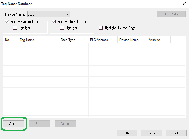
Select Add…

Under the tag information the device name default to DEV001 that we set up last time. We will call the tag PANEL TO PLC. The tag data type can be either an unsigned int 16 or BCD int 16.
Under the PLC Address, the memory type for our Modbus communication is 4 and the address is 1 which is the first memory address. This will give us an address of 40001 for the panel to plc address. Select Add.
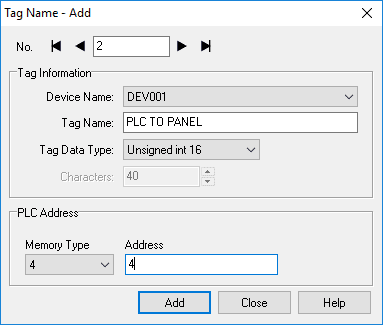
We will now set up the PLC to panel address. Name this PLC TO PANEL and select the tag data type as unsigned int 16. The memory type will be 4 and the address will be 4, so the Modbus address will be 40004.
Note: Since the Panel to PLC address automatically uses up to three addresses (40001, 40002, 40003) the next available one is 40004.
Select Add. We can then select close so we are not adding any more tags to the database.
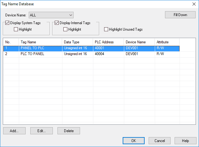
Select the panel to PLC tag and select OK.
We have now finished setting up our Panel to PLC communication. Select the PLC to the Panel tab.
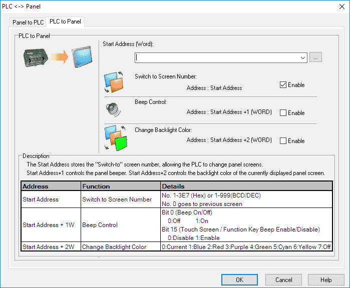
The PLC to Panel control will allow us from the PLC to switch screen numbers, control the beep (sound) and change the backlight of the C-More Micro HMI panel.
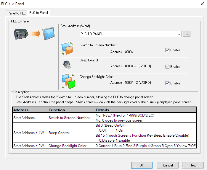
Select the Starting Address (Word) to our PLC TO PANEL database tag that we set up. Ensure that the Switch to Screen Number, Beep Control, and Change Backlight Color is enabled.
Note: This PLC to panel word will use 40004, 40005, and 40006 to control the panel from the PLC.
Select OK.
Transfer Screen Program to C-More Micro HMI Panel
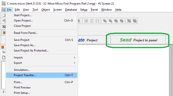
Select File | Project Transfer… from the main menu or use the shortcut key Ctrl +T. You can also select Send Project to panel on the main screen.
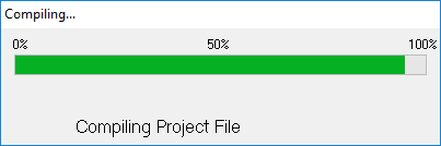
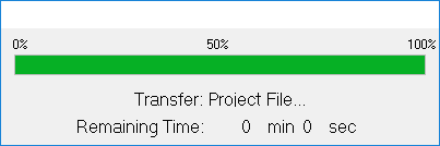
The program will then compile.
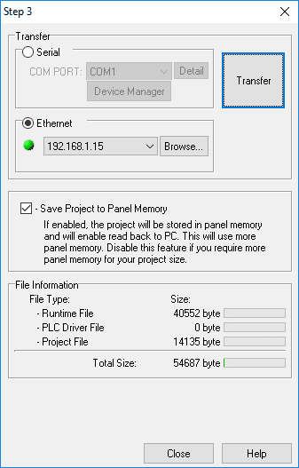
We will transfer by the Ethernet connection. If there is a connection it will be displayed and a green symbol will indicate that it is available to communicate. If this is not available you can hit the Browse button to scan the network for the connected C-More Micro HMI panel.
Hit the Transfer button.
Select OK after the transfer completes.
C-More Micro HMI Panel Control from PLC
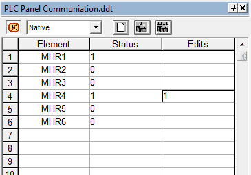
We can now go online with our Do-More Designer software and use the Data View monitor to monitor the Panel to PLC and PLC to Panel registers.
Panel to PLC
MHR1 – Modbus 40001 – Current Page being displayed on the panel
MHR2,3 – Modbus 40002, 40003 – Key Assignments press on the panel
PLC to Panel
MHR4 – Modbus 40004 – Switch to screen number. A number written to this area will change the screen on the panel.
MHR5 – Modbus 40005 – Bit 0 is the beep on the panel – 0:off 1:on – Bit 15 is the touch screen/function key beep enable/disable. 0:Disable 1: Enable
MHR6 – Modbus 40006 – Change backlight color – 0:current, 1:Blue, 2:Red, 3: Purple, 4: Green, 5: Cyan, 6: Yellow, 7:Off
Control and monitoring of the screen from the PLC is an easy process. Once the registers are set up, we can just read or write the information that we want.
Download the PLC and C-More Micro program here.
Watch the video below to see the above panel to PLC and PLC to panel communication works in our C-More Micro HMI Panel.
C-More Micro Panels from Automation Direct
https://www.automationdirect.com/adc/Shopping/Catalog/HMI_(Human_Machine_Interface)/C-more_Micro_Panels
C-More Micro – Graphic Panel (EA3 Series) User Manual and Quick Start Guides
https://cdn.automationdirect.com/static/manuals/ea3mguserm/ea3mguserm.html
EA3-T4CL C-More Micro Specifications
https://cdn.automationdirect.com/static/specs/ea3t4cl.pdf
C-More Micro Programming Software V4.30
http://support.automationdirect.com/products/cmoremicro.html
This free software will enable you to program all of the C-More Micro HMI units. It includes a simulator for your application.
Next time we will look at creating a common screen menu in the C-More Micro HMI Panel.
Watch on YouTube : C-More Micro HMI First Program Part 2
If you have any questions or need further information please contact me.
Thank you,
Garry
If you’re like most of my readers, you’re committed to learning about technology. Numbering systems used in PLC’s are not difficult to learn and understand. We will walk through the numbering systems used in PLCs. This includes Bits, Decimal, Hexadecimal, ASCII and Floating Point.
To get this free article, subscribe to my free email newsletter.
Use the information to inform other people how numbering systems work. Sign up now.

The ‘Robust Data Logging for Free’ eBook is also available as a free download. The link is included when you subscribe to ACC Automation.