We will now look at shapes like lines, rectangles, circles, and frames that we can use on our C-More Micro HMI. The C-More Micro HMI Panel software uses virtual components called Objects. These objects are programmable to simulate the functions that you require on your automation project. Pushbuttons, Switches, meters, and graphs are just a few of the objects that are available to you.
We can place several of these objects on the one-panel screen and have multiple panel screens. This helps you produce simple, intuitive looking human-machine interfaces.
We will be looking at our program we have so far developed (Simulate Project) and add shapes to our blank page. The navigation of the objects and additional information will also be discussed. Let’s get started.
Previously in this C-More Micro HMI Panel series, we have done the following:
System Hardware – Video
Installing the Software – Video
– Update Automation Direct Software C-More Micro HMI Video
System Setup Screens – Video
First Program – Video
First Program Part 2 (PLC < – > Panel) – Video
Common Screen Menu – Video
Simulate Project – Video
Navigation of the C-More Micro Software Objects
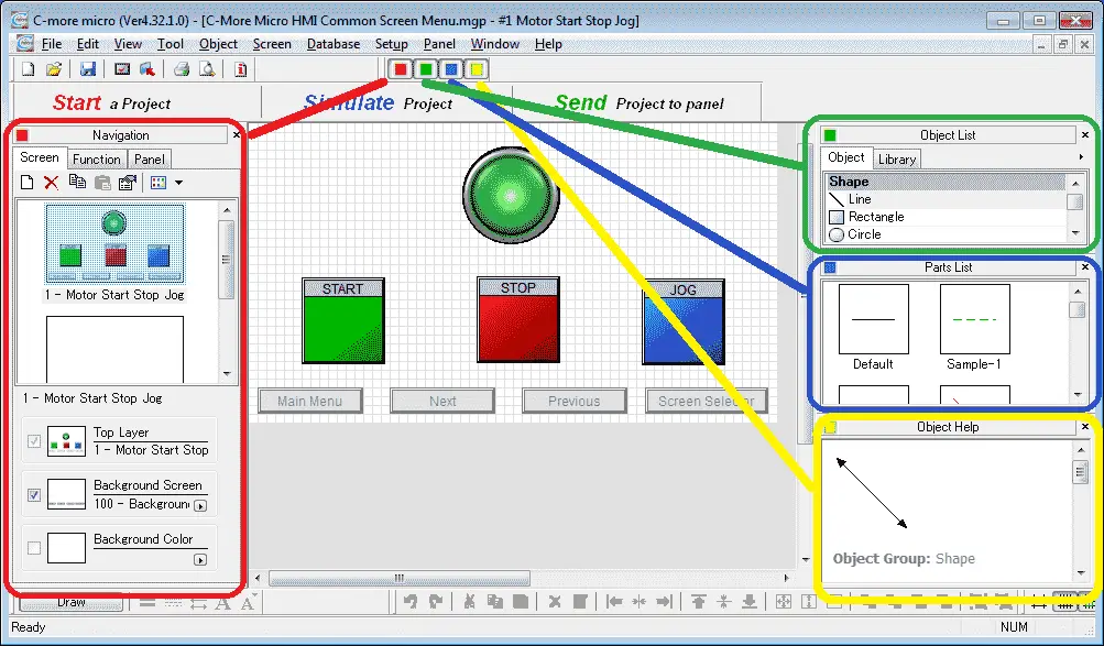
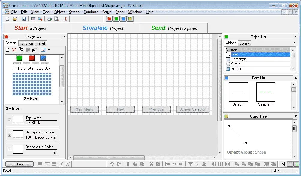
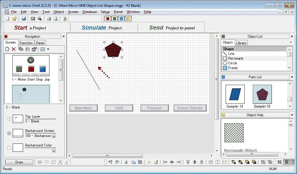
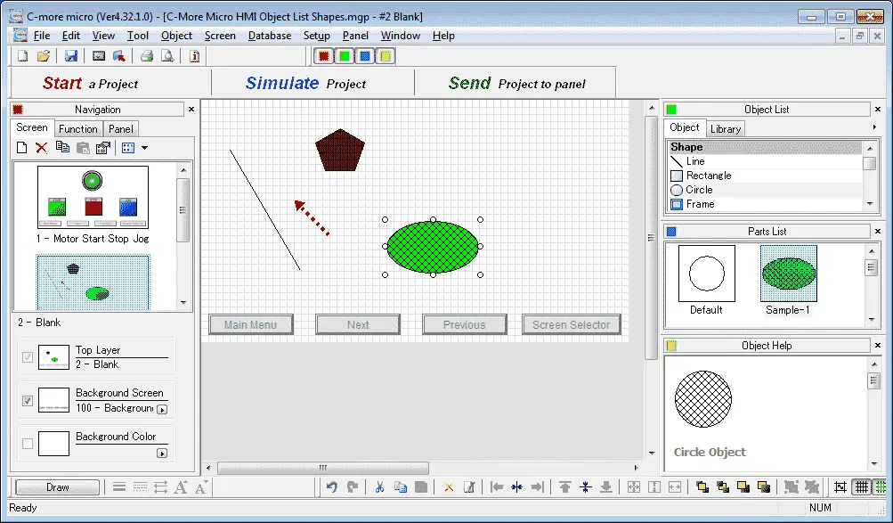
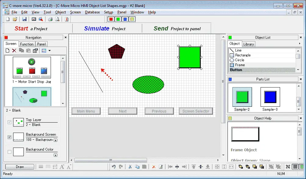
Each color located on the main screen menu will control a window. Clicking the color will hide the menu if it is currently being displayed. If it is not being displayed then the menu will be shown.
Red – This will control the navigation window. The navigation window will show you the screens, functions, and panel information.
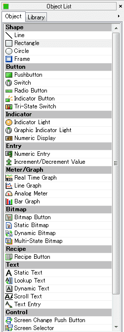
Green – This is the Object List menu. It contains all of the items that can be used on your HMI screen. We will be looking at the Shape objects later.
Blue – This is the Parts List. These are designed shapes that are in the list for you to use. The parts displayed will be for the object that has been selected in the object list. They are available so you do not have to create the object from scratch every time.
Yellow – The Object Help will provide additional information on the object that has been selected in the Object List.

Another way to call the Objects for your HMI project is to use the main menu. Main Menu | Object | Shape | Line… would be the way to call up the line to be placed on your page in the c-more micro.
Shapes Object – C-More Micro
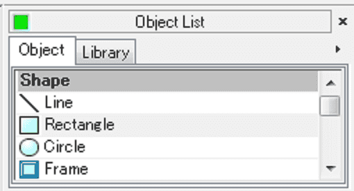
There are four different shapes that you can use to draw on your HMI cmore micro page. Line, Rectangle, Circle, and Frame are the choices that you have when using shape objects.
Tag Name Database – C-More Micro Shapes

We will use the following four addresses to control the visibility of our shapes on the cmore micro HMI.
MI2 – Discrete On/Off – Modbus Address 10002 – Read Only
MI3 – Discrete On/Off – Modbus Address 10003 – Read Only
MI4 – Discrete On/Off – Modbus Address 10004 – Read Only
MI5 – Discrete On/Off – Modbus Address 10005 – Read Only
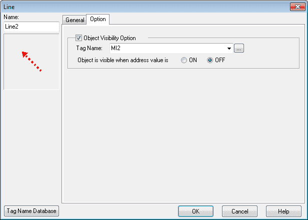
Line Object – C-More Micro Shapes
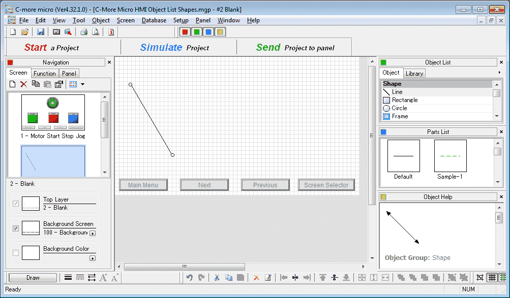
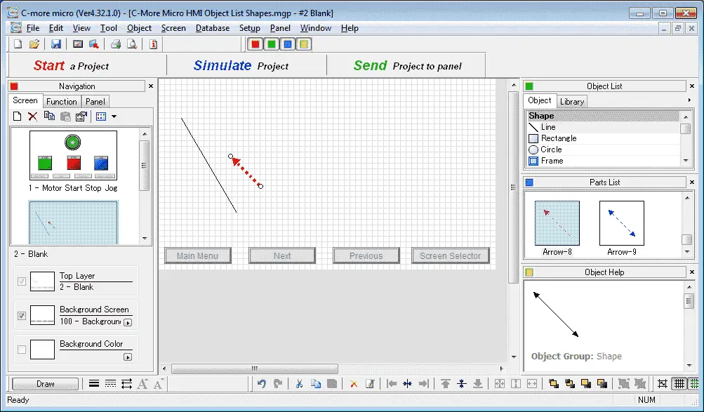
We will now put a line object onto our page #2 Blank Screen. Select page 2 from our navigation window.
Locate the line shape under the Object List window. Click and hold the shape and drag the line to the screen page location that you want the line to be displayed. Let go of the mouse button and the line window menu will appear.
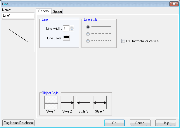
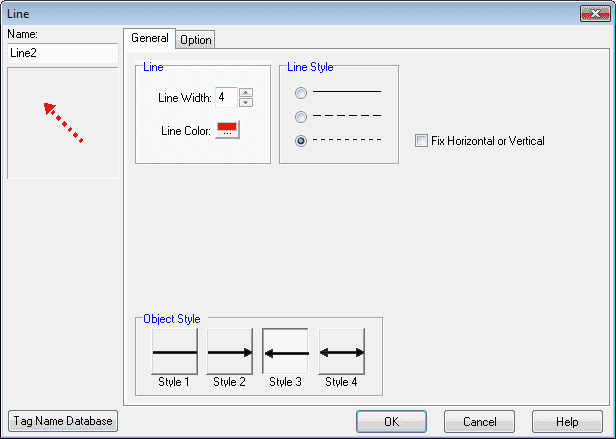
We have several options for the line. Width and color can be selected and the line style has three options for you. The fixed horizontal or vertical selection will only allow the line to be vertical or horizontal. The object style will allow you to place an arrowhead on either end or both.
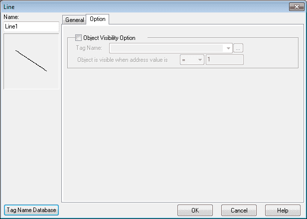
The Options tab will allow you to control the visibility of the object from the PLC Tag Name Database.
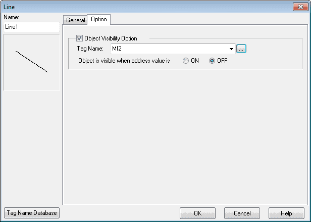
We will select the Object Visibility Option and use the Tag Name MI2. Select Off for the object is visible when the address value is selected.
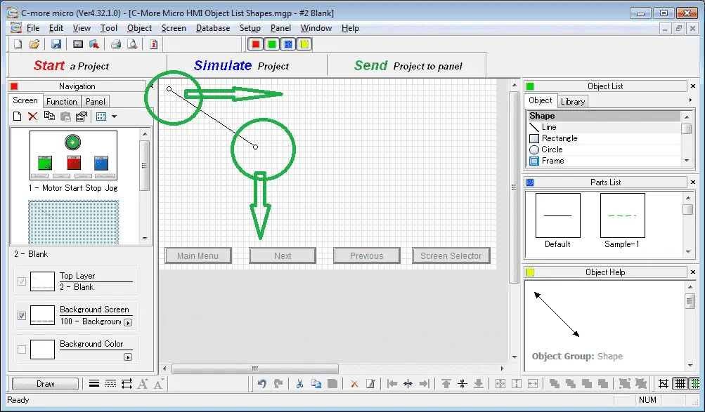
Using the circles at the ends of the line you can move the line to the length and direction that you want it on the HMI screen/
The object can always be modified by right-clicking on it and selecting properties.
Line from Parts List
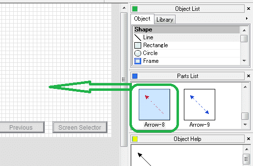
Scroll down the parts list until you see Arrow-8. We will click and drag this onto our HMI screen.
The line window appears again to allow us to modify the default values of this part. Change the line width to 4 and then select the Options tab.
Select the object visibility option and set it for our tag name MI2. The object is visible when the address value is OFF.
We can now position this object line from our parts list on the screen.
Rectangle Object – C-More Micro Shapes
We will now put a rectangle object on our screen.
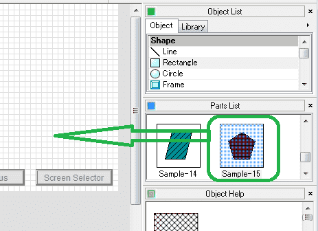
Select Rectangle under the Shape in the object list. Scroll down in the parts list and select Sample-15. Click and drag this onto the HMI screen.

The rectangle window will now be displayed.
Name: Rectangle1 – This is the default name, but you can name this object anything that you want.
Outline – This allows you to set the line width and line color.
Fill – This will allow you to set the fill color and pattern.
Object Style – There are five different styles to choose from for the object. The number of sides can also be chosen. We will leave this as the default and select the Options tab.
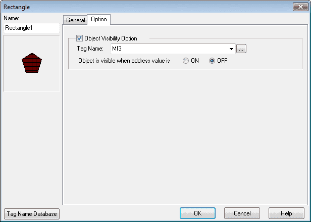
Select the object visibility option. The tag name will be MI3 and the object is visible when the address value is OFF. Select OK.
We can now use the mouse to position the rectangle object on our HMI screen.
Circle Object – C-More Micro Shapes
We will now put a circle object on our screen.
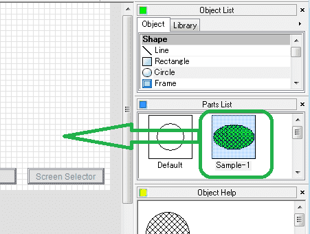
Select Circle under the Shape in the object list. Under the parts list select Sample-1. Click and drag this onto the HMI screen.
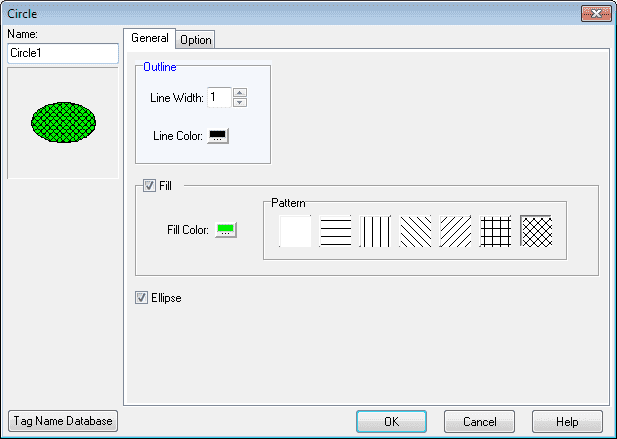
The circle window will now be displayed.
Name: Circle1 – This is the default name which you may change if you wish.
Outline – This will allow you to set the line width and color.
Fill – This will allow you to fill the object with a color and pattern. We will leave this as the default.
Ellipse – This will change the circle to an ellipse shape.
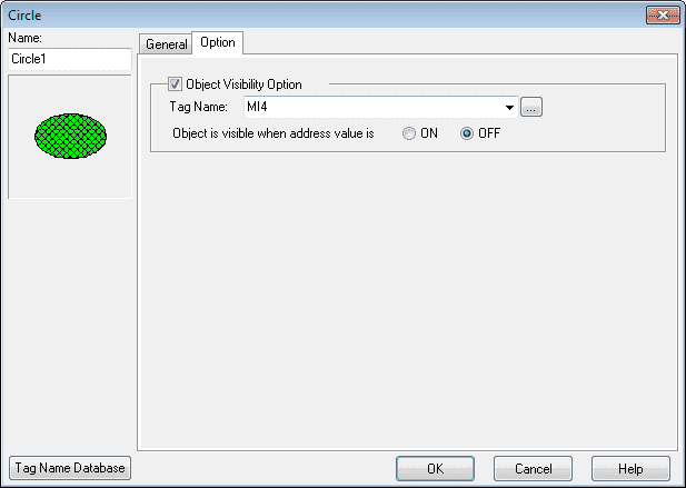
Hitting the Options tab, we will select the tag name for visibility to MI4. The object is visible when the address value is OFF. Hit OK.
You can now use your mouse to shape the circle object.
Frame Object – C-More Micro Shapes
We will put a frame object on our screen from the parts menu.
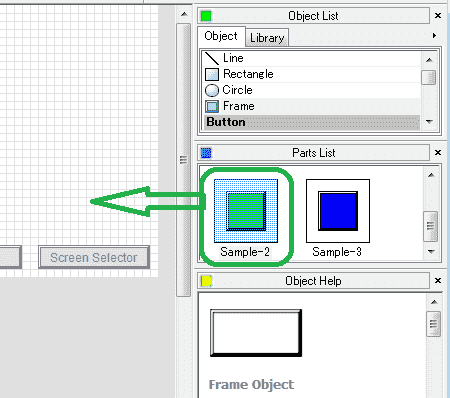
Select Frame under the Shape in the object list. Under the parts list scroll down and select Sample-2. Click and drag this part onto the HMI screen.
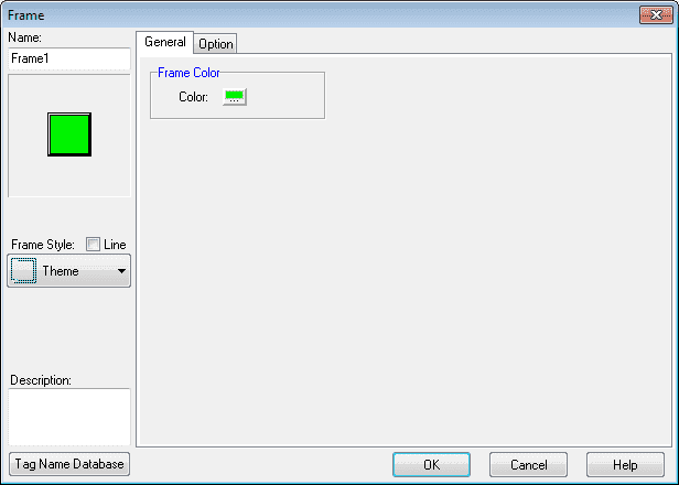
The Frame window will now be displayed.
Name: Frame1 – This is the default name that can be changed.
Frame Color – You can select the frame color.
Frame Style: You can select the frame style from a list by the dropdown menu. We will leave this as the default.
Description: We can add a description of the object that we are using.
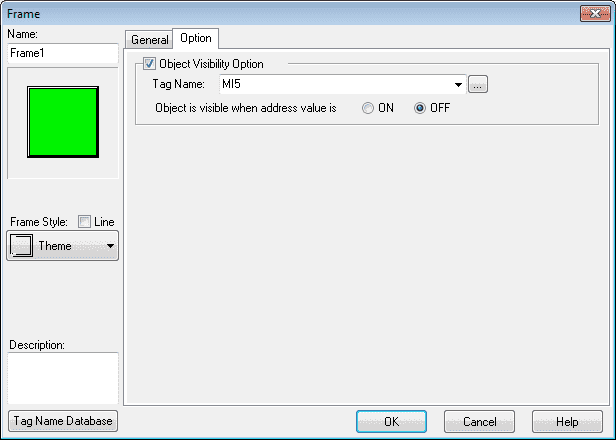
Hitting the Options tab we will use the tag name MI5 for the object visibility option. The object is visible when the address value is OFF. Hit OK.
We can now use the mouse and size and move our frame object.
PLC Program Additions – C-More Micro Shapes
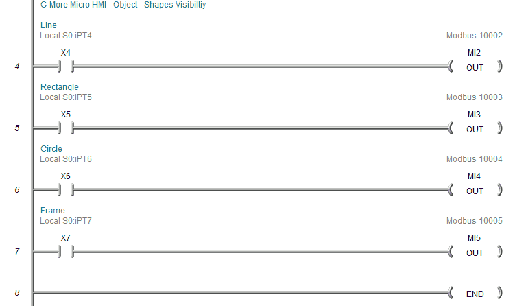
Using the program we previously developed, we will add four new rungs to control the visibility of the object that we have just created.
We selected that the Modbus output bit must be Off to be visible on the screen. So when we turn the output on the object will be invisible.
Download the PLC and C-More Micro program here.
Watch the video below to see the Object Shapes in action on our C-More Micro HMI Panel. This will also demonstrate the PLC ladder code for visibility.
C-More Micro Panels from Automation Direct
https://www.automationdirect.com/adc/Shopping/Catalog/HMI_(Human_Machine_Interface)/C-more_Micro_Panels
C-More Micro – Graphic Panel (EA3 Series) User Manual and Quick Start Guides
https://cdn.automationdirect.com/static/manuals/ea3mguserm/ea3mguserm.html
EA3-T4CL C-More Micro Specifications
https://cdn.automationdirect.com/static/specs/ea3t4cl.pdf
C-More Micro Programming Software V4.30
http://support.automationdirect.com/products/cmoremicro.html
This free software will enable you to program all of the C-More Micro HMI units. It includes a simulator for your application.
Next time we will look at the button objects in the C-More Micro HMI Panel.
Watch on YouTube : C-More Micro HMI Object List Shapes
If you have any questions or need further information please contact me.
Thank you,
Garry
If you’re like most of my readers, you’re committed to learning about technology. Numbering systems used in PLC’s are not difficult to learn and understand. We will walk through the numbering systems used in PLCs. This includes Bits, Decimal, Hexadecimal, ASCII and Floating Point.
To get this free article, subscribe to my free email newsletter.
Use the information to inform other people how numbering systems work. Sign up now.

The ‘Robust Data Logging for Free’ eBook is also available as a free download. The link is included when you subscribe to ACC Automation.