Many people ask me what I do when looking at a new PLC model or system. My approach is very straight forward and we will view this in action with this Click PLC series. This series will go from examining the hardware to programming and communicating to the PLC in several ways. If you have questions along the way, please let me know.
Determine the Inputs and Outputs – Click Hardware
The five steps to PLC program development will determine the inputs and outputs required in our system.
1 – Define the task
2 – Define the inputs and outputs
3 – Develop a logical sequence of operation
4 – Develop the PLC program
5 – Test the program
There are several reasons why we are using the Click PLC. Here are just a few.
– Investment is low for the hardware and the software is free
– Standalone PLC with built-in I/O
– Communication ability – Ethernet Port, RS232, RS485 – support for protocols such as Modbus RTU, Modbus TCP, etc.
– Ability to expand the system with a variety of modules including RTD and Thermocouple inputs directly.
The following should be downloaded from the Automation Direct Website.
Click PLC User Manual – You can download the entire manual or just the sections that you need at the time.
https://www.automationdirect.com/adc/Manuals/Catalog/Process_Control_-a-_Measurement/Temperature_-z-_Process_Controllers
Click PLC Software – This is required to configure, program and document your Click PLC.
http://support.automationdirect.com/products/clickplcs.html
Configuring the Click Hardware System
We can now build our PLC system from the following website.
http://www.automationdirect.com/adc/Shopping/Catalog/Programmable_Controllers/CLICK_Series_PLCs_(Stackable_Micro_Brick)
The Click PLC unit currently comes in 5 different types. The following table will show the different units:
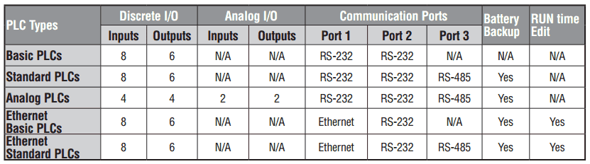
A system can have up to eight (8) additional units connected to it. The following shows a picture of a system that has the maximum amount of units.
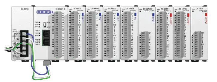
Each unit can be any of the following:
DC I/O – These units can be wired up either sinking or sourcing. (NPN / PNP) This applies to both the input and output units.
AC I/O – 100 – 120 VAC, 24VAC/DC, Relay Outputs, 17-240VAC Outputs, and combination output units are available.
Analog I/O – The standard 0-20mA, 4-20mA, 0-10VDC inputs, and outputs are available with either 12 or 13-bit resolution. There are also temperature input modules that accept 4 RTD or thermocouple inputs.
Wiring our Click PLC Hardware
Additional resources on wiring:
https://accautomation.ca/heres-a-quick-way-to-wire-npn-and-pnp-devices/
https://accautomation.ca/get-rid-of-surges-that-are-destroying-your-plc-outputs/
https://accautomation.ca/the-secret-of-getting-rid-of-noise-on-your-analog-signal/
All of the PLC units need 24VDC power to operate. The maximum amount of current required on the power supply is 1.3 amps. This will cover any combination of I/O modules requirements of the Click PLC.
The free Click Programming software has a Setup | System Configuration menu that will show you the modules used and supply power required. This is also where we can configure the analog and see the addressing of the physical I/O.
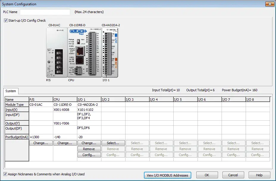
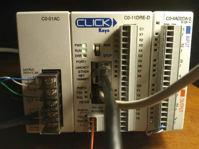
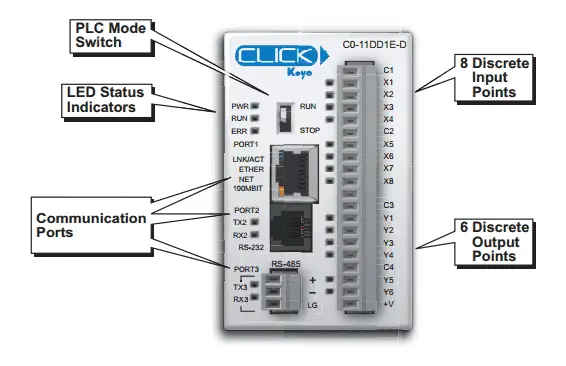
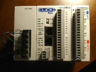
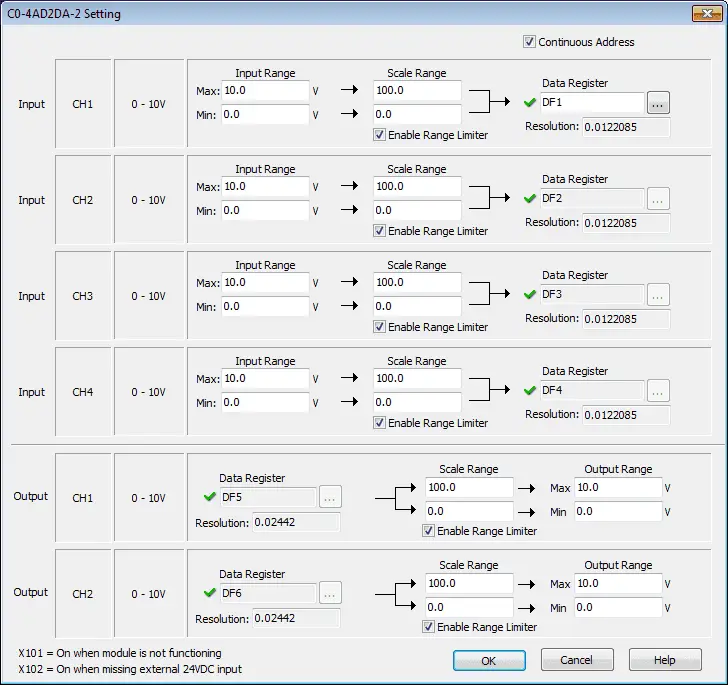
The Click PLC that we will be using is the C0-11DRE-D. It has three communication ports, 8 input, and 6 output points. We also have an analog module C0-4AD2DA-2. This is a combination module that has 4 input points (0-10VDC) and 2 output points (0-10VDC). The power supply is a C0-01AC. This will cover any combinations that we require on our PLC.
Note: The analog will give you a range. We can configure the module using the Click Programming software to set the physical range and the scaling factors without the need for programming.
Connection to the PLC will require cables. Our PLC has three different communication ports. All three are capable of programming our unit with the Click programming software. Here is the link to get the pinout of all of the cables.
http://www.automationdirect.com/static/specs/directsoftcables.pdf
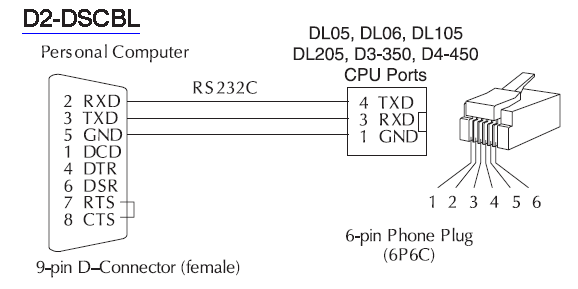
The most common method is to use RS232. A RJ12 port is used on the PLC to communicate. If your computer has a DB9 (9 pin D-shell male) serial connector then you can use the D2-DSCBL cable.
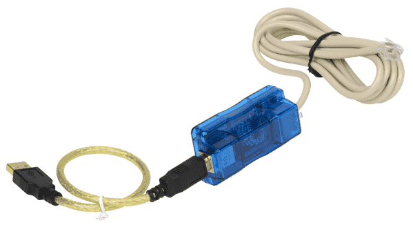
Most computers will not come with serial ports anymore. So we can still utilize the RS232 communication by using a USB port. The EA-MG-PGM-CBL will connect to your USB port and convert to RS232 to communicate.
RS485 can be utilized by using the USB-485M converter. This will communicate from your USB port convert to RS485 and communicate to the RS485 port (2-wire) on the PLC.
https://accautomation.ca/usb-to-rs485-pc-adapter-installation/
The Ethernet cable connection is by far the quickest to communicate to the Click PLC. It uses a standard RJ45 Ethernet connection.
Next time we will install the software and communicate to the Click PLC in three different ways. RS232 RS485 and Ethernet.
Watch on YouTube: Click PLC System Hardware
Watch on YouTube: Wiring (Testing) Analog PLC Input Click
If you have any questions or need further information please contact me.
Thank you,
Garry
If you’re like most of my readers, you’re committed to learning about technology. Numbering systems used in PLC’s are not difficult to learn and understand. We will walk through the numbering systems used in PLCs. This includes Bits, Decimal, Hexadecimal, ASCII and Floating Point.
To get this free article, subscribe to my free email newsletter.
Use the information to inform other people how numbering systems work. Sign up now.

The ‘Robust Data Logging for Free’ eBook is also available as a free download. The link is included when you subscribe to ACC Automation.