FREE CLICK PLC Software: Is It REALLY That Easy? This industrial-proven hardware and software have been around for 16 years. It has been regularly modified and updated to ensure it remains current and relevant.
A Programmable Logic Controller (PLC) is a type of industrial control system used to automate machinery and processes. It is designed to be user-friendly and cost-effective, making it suitable for small to medium-sized applications. Click PLCs program using the Click PLC Programming software, which enables users to easily create and modify ladder logic control programs.
We will configure and assemble a Click PLC system. We will then download, install, and program this system using the Click PLC Programming Software. Let’s get started.
Our entire Click series can be found here.
All of the previous information for the Click PLC can be applied to the Click PLUS.
Configuration of a Click PLC
The CLICK PLC family features a compact design and easy programming, making it ideal for small applications and beginner projects. When we refer to ‘compact,’ this is a reference to the number of digital and analog inputs and outputs. The maximum number of digital inputs and outputs (I/O) is 156. This could also be 60 analog Input/output (I/O) channels. The CLICK PLUS series features include Wi-Fi capability, motion control, data logging, and more.
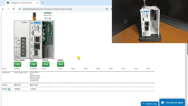
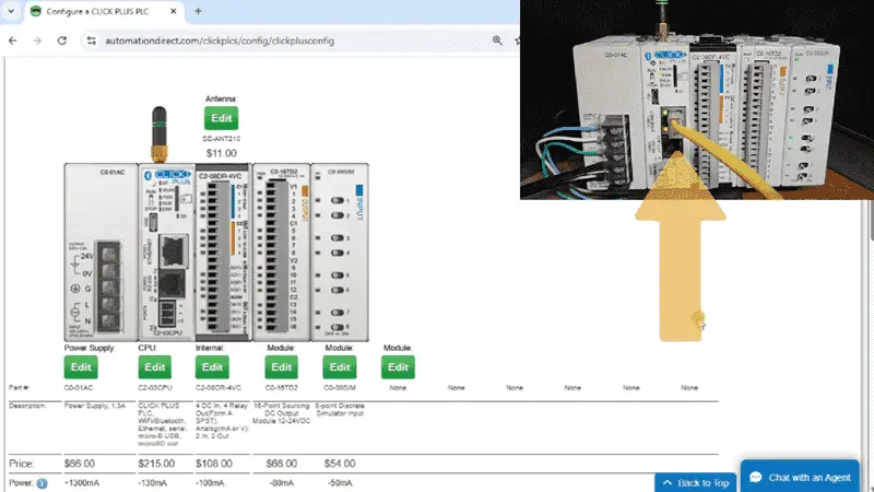
The website will help configure a system. This ensures that you include all of the essential components required for your system. Besides including all of the system components, it will also display the power necessary for your chosen system. The Click PLC modules (Cards) “Click” together to form your system.
CLICK PLC extreme value systems offer:
- Free, easy-to-use software with a simple instruction set
- Easy I/O expansion up to 156 discrete or 60 analog (2-slot CLICK PLUS CPU)
- PID loop control (up to 8 loops) with Ethernet-capable and wireless CPUs
- Enhanced security measures (ping disable, port management, passwords, etc.)
- ASCII, Modbus RTU/TCP, MQTT, and Ethernet/IP communications (dependent on model)
Connect the Ethernet port to your network. This will automatically get an IP address for your system. We can now go to the next step of installing the Click Programming Software.
Installation of the Click Programming Software
Download and install the Click Programming Software from Automation Direct’s Website. The current version is 3.70, released in February. This software does not create a burden on your computer system, which has a minimum of 2 MB of RAM and a 1 GHz clock speed. It will run on your Windows 10 or Windows 11 operating system.
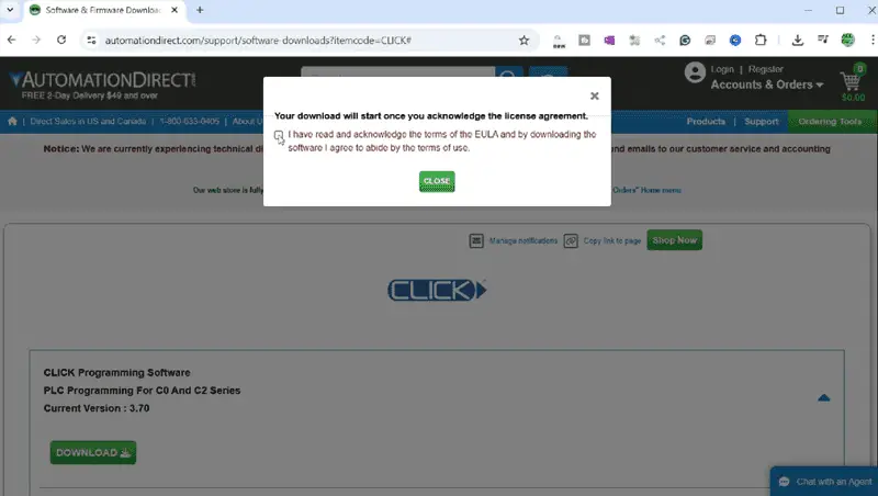
Select the download link. You must acknowledge the software licence agreement. Select and close the pop-up window.
Select the download link again. This time, you will be prompted to enter your email address and then confirm it. Select the new download link that is now active. Our software will now be downloaded. This 423,309 KB file will take a little time to download fully.
Right-click on the download file and select Extract All. This will extract the compressed file, allowing us to install the software.
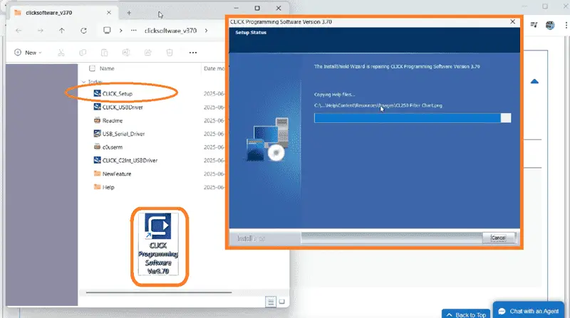
Double-click the Click_Setup installation file from the uncompressed folder to start the installation of the Click Programming Software. A message will be displayed once the software has been installed. Select Finish. An icon will be placed on your desktop, allowing you to start the Click PLC Programming Software easily.
Click PLC Communication / Firmware Update
Start the Click Programming Software by selecting the Icon on your desktop. The What’s New screens will be displayed.
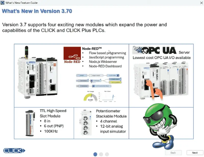
This great feature highlights new, different, or updated items in the software. If you do not want to display this next time, click the option and select Close.
The startup window will be displayed. Select Connect to PLC.
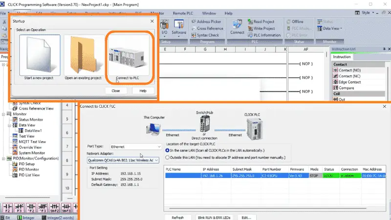
The Connect to PLC window will now be displayed. You will see that we can select USB, Serial, or Ethernet. Select Ethernet. We had already plugged our Ethernet cable in. The Click Programming Software automatically searches the network and reports back the connected PLC controllers. This will show you the current IP address, Firmware Version, and MAC address. Since we have only one Click PLC on our network, this is the default one. Select Connect.
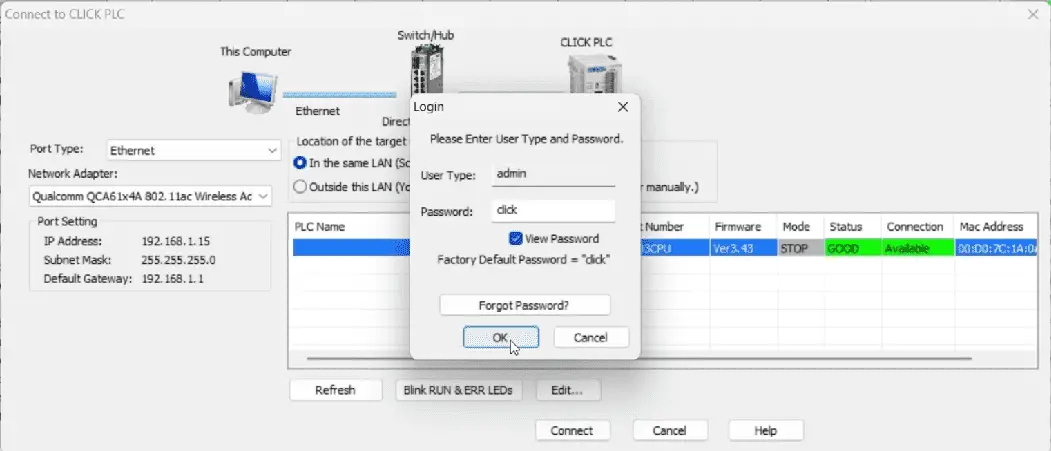
The login window will now be displayed. Since this is a new install, use the password ‘click’ and select OK.
A warning message will be displayed indicating that there is no project file in the Click CPU. Select OK.
Along the bottom of the Click Programming Software, you will see the IP address and the mode of the PLC. The PLC is currently in STOP.
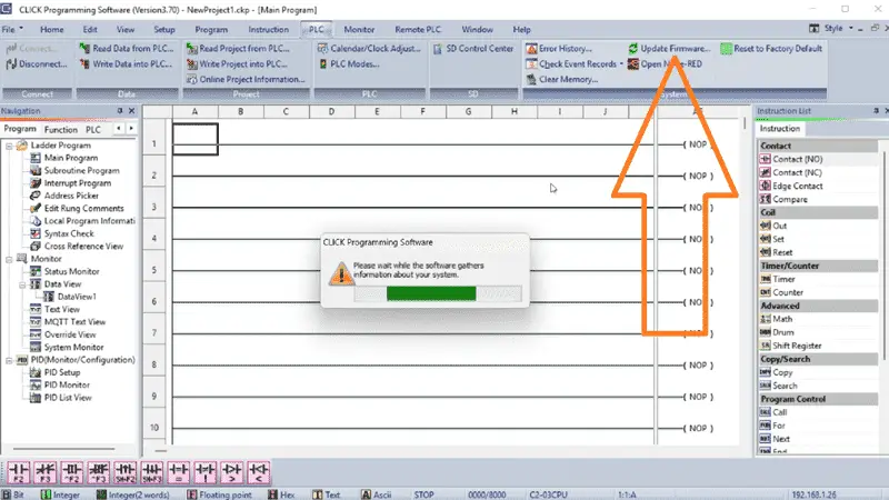
Select Update Firmware from the Main Menu | PLC. Since this is a new controller, we want to ensure that the software is up to date. Information is read from the connected PLC and then displayed on the Update Firmware Window.
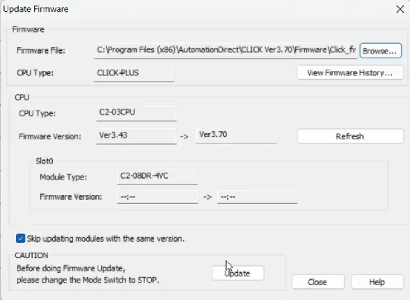
Our current firmware version is 3.43, and we will be updating to 3.70. Select Update.
A warning message is displayed, informing us that the PLC CPU switch must be in STOP mode and that we want to update. Select YES.
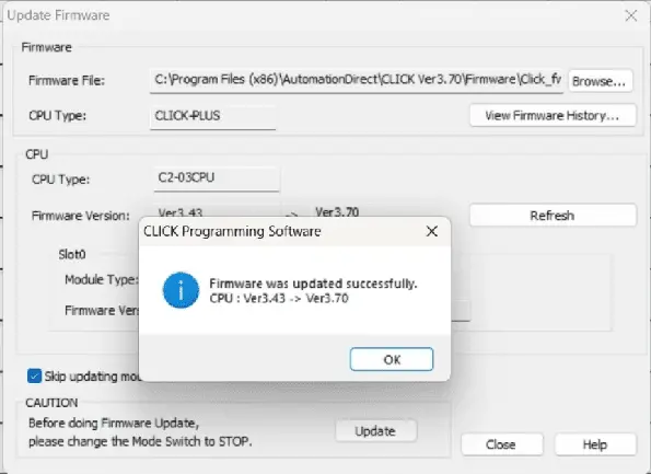
The Click PLC CPU firmware will now be updated. During this time, do not remove power. When the firmware update is successful, a message window will be displayed. Select OK. Select Close for the Update Firmware window.
Click PLC Input / Output Addresses (I/O)
While still online to the Click PLC, select System Configuration from the main menu | Setup. The system configuration window message will display, indicating that it will identify the connected CPU and I/O modules for the system. Select OK.
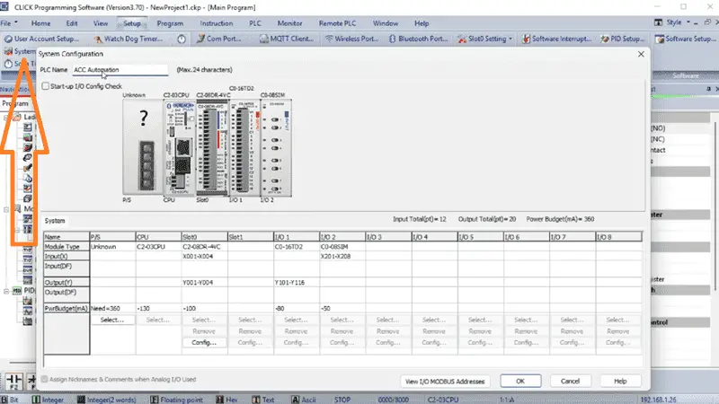
In the System Configuration window, we can enter a name for our Click PLC. In our case, we will enter ACC Automation. This will be the name of the PLC when we connect next time.
You will see the name of the CPU, and the modules are listed in the order in which they are connected in the PLC.
Our power supply is unknown because there is no communication of it to the CPU. Select Select… The “Select a Power Supply” window will be displayed. Select the C0-01AC unit that we have connected and select OK.
The system configuration will now show the power supply and the amount of current that it provides to the CPU and modules.
Under Slot 0, select the Config button. The C2-08DR-4VC Setting window will be displayed. We can set the scaling of the analog input and outputs on this screen. Select DF1 as the starting address for the analog. The Address Picker allows you to select the desired option easily. Select OK.
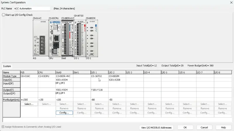
The system configuration will show you the addresses of the digital discrete inputs and outputs on slot 0. This is X1 to X4 for the inputs and Y1 to Y4 for the outputs.
The first module connected to the CPU will have 16 outputs. The addresses for these digital discrete outputs are Y101 to Y116. X201 to X208 are set for the simulator input on the far right of the CPU unit.
Select “View IO Modbus Addresses” to view the Modbus addresses for the system configuration inputs and outputs.
Select OK on the System Configuration window. Since we have changed the configuration, a message window will be displayed indicating that we must transfer the modified configuration to the Click PLC. Select OK.
Before transferring, select User Account Setup from the Setup menu on the main menu. In the User Account Setup window, choose Password Disable Requirement and then select OK.
On the first rung, we will put an END instruction. This ensures that an error will not occur if the PLC is put in RUN mode. Save the program with the default name under the File menu on the main menu.
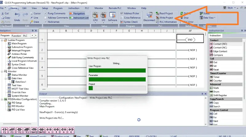
On the Home tab of the main menu, select Write Project. This will check for errors in your program and then compile it. The “Write Project into PLC” window will then be displayed. Select OK.
Our project will now be transferred to the Click PLC connected. A complete transfer message will be displayed upon completion. Select OK.
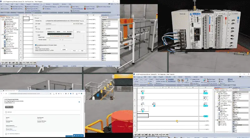
Watch the video below to see the configuration and transfer.
Click PLC First Program
We can now write our first Click PLC program. The Click PLC Programming Software allows you to customize the windows to suit your preferences. Click and hold the Navigation Window and move it beside the Instruction List window.
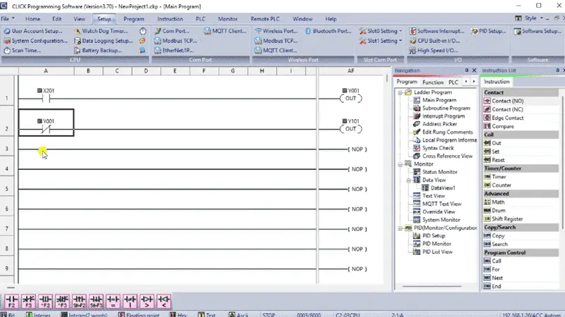
Our first rung will utilize the first switch, X201, and control the first output, Y1. The addresses were automatically assigned when we looked at the configuration.
The second rung will use the output Y1 as the input to control Y101. The input will be a negative or normally closed logic.
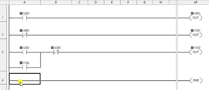
Rung three will be a simple start-stop circuit. X202 will turn the output on, while X203 will turn it off. The output will be used as an input to seal the X202 start input. This will allow X202 to be momentary, so the output remains on.
Rung four will contain our END instruction. This marks the end of the logic and instructs the CPU to continue the SCAN of the PLC.
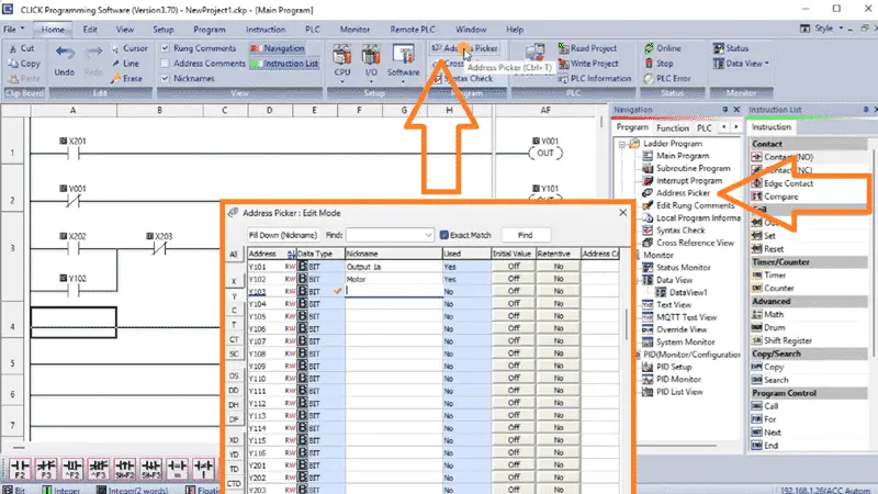
Select the Address Picker from the HOME tab. We can assign names to each of the inputs and outputs that we have used in our program. This document makes the program easier to understand.
Select “File Save As” under the File menu option. We can now name our project so that it is easier to find in the future. Select Save.
Write the project into the PLC.
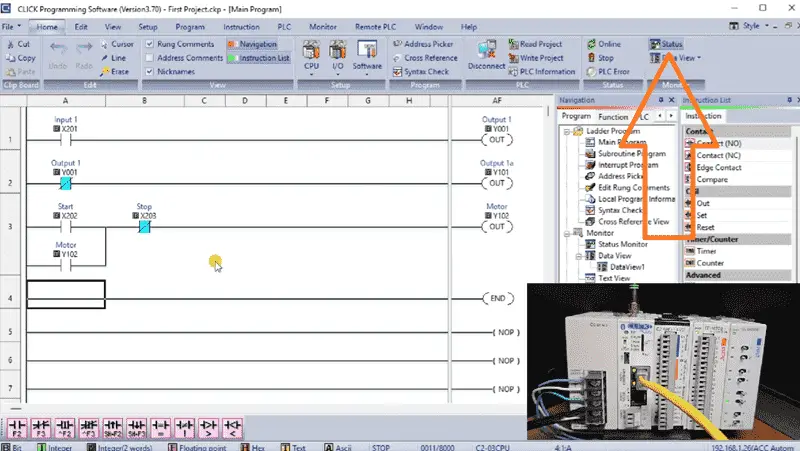
Once the project has been written, select STATUS monitor from the HOME tab. This will allow you to visually see the input and output conditions as the program executes.
The PLC will scan from left to right, top to bottom. The output from the previous rung is available for use by the next rung.
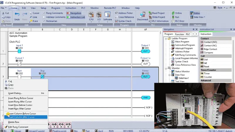
Right-clicking on a rung, we can select Edit Rung Comment. This will enable us to document our program more thoroughly. Remember to always save and transfer your program after making any modifications so you won’t lose any data in the event of a power failure or computer crash. Watch the video below to see the programming and transfer to the Click PLUS PLC.
We discovered the essential components of a Click PLC system and how they work together to provide a reliable and efficient automation solution. We broke down the key elements that make up a Click PLC system, including the PLC unit, I/O modules, communication protocols, and programming software. Whether you’re a seasoned engineer or just starting out with PLC programming, this provided a comprehensive overview of the Click PLC system and its components.
Learn more about how to design, build, and program your own Click PLC system with confidence by clicking here. Click here to see how you can learn PLC programming using the Machine Simulator by Nirtec. This will provide machine scenes that you can program.
Download the Click PLC Programs here.
Watch on YouTube: FREE CLICK PLC Software: Is It REALLY That Easy?
Our entire series on the Click PLC can be found here.
The Click PLC can be programmed using free Click programming software from Automation Direct.
Here is a link to the software. Version 3.70
The entire Click PLC series before the Click PLUS release can be found here.
All previous posts and information are still valid with the Click PLC lineup.
YouTube Click Playlist
YouTube Click PLUS Playlist
Click and Click PLUS PLC Overview
Click and Click PLUS PLC Videos from Automation Direct
If you have any questions or require further information, please don’t hesitate to contact me.
Thank you,
Garry
If you’re like most of my readers, you’re committed to learning about technology. The numbering systems used in PLCs are not difficult to understand. We will walk through them, including Bits, Decimal, Hexadecimal, ASCII, and Floating Point.
To get this free article, subscribe to my free email newsletter.
Use the information to educate others on how numbering systems work.
Sign up now.

The ‘Robust Data Logging for Free’ eBook is also available as a free download. The link is included when you subscribe to ACC Automation.