This post is a further follow-up from my original ‘Here’s a Quick Way to Understand PLC Inputs and Outputs.’ There are two different kinds of PLC inputs, Discrete and analog. Discrete inputs are either ‘ON’ or ‘OFF’; 1 or 0. You can think of them as a single switch. Analog inputs have a range to them. They are inputs that usually will sense pressure, temperature, height, weight, etc. They typically have one of the following signals inputted into the PLC: 4-20mA, 0-10VDC, 1-5VDC.
PLC Discrete Inputs – On / Off
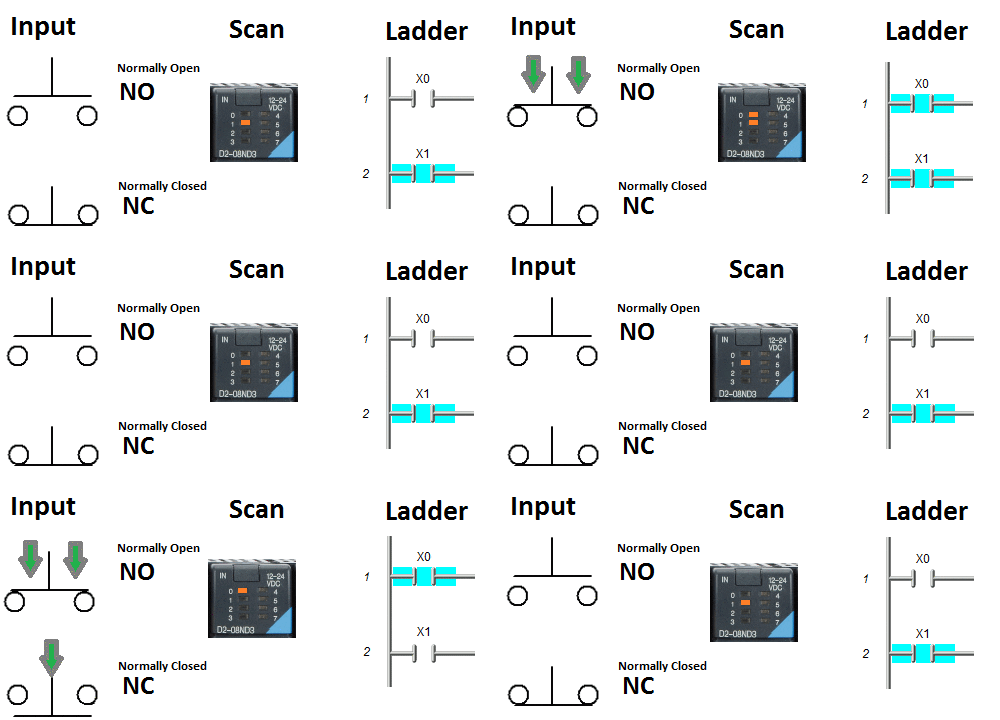
The above diagram has two inputs—a normally open (NO) and a normally closed (NC). Consider the input condition when discussing ordinary opening and closing if no one touches anything. A normally open contact will not turn on the Input to the PLC card in its ‘normal state. The normally closed contact will turn on the Input to the PLC card in its ‘normal condition.
Normally Open Input
The NO contact, when activated, will complete a circuit and turn on the PLC input. Ladder logic will then turn on if you use a normally open (Examine On) input in your program. See the above diagram.
Normally Closed Input
The NC contact, when activated, will break a circuit and turn off the PLC input. Ladder logic will turn off if you use a normally open (Examine On) input in your program. See the above diagram.
PLC logic can convert any signal by using normally closed (Examine Off) inputs in the program. As you can see from the diagram above, this can get tricky to determine the on/off condition of the Input. In the field, I usually look at the PLC input lights and wiring diagrams to select the current state of the Input. This is before diving into the program to troubleshoot.
Here is a link to wiring up discrete 3-wire sensors in the field. Here’s a Quick Way to Wire NPN and PNP devices
PLC Analog Inputs – Voltage or Current Range
An analog input converts a voltage or current level into a digital value that can be stored and processed in the PLC. They use words to determine the signal coming from the device.
Example:
4 – 20 mA current Input – 8-bit resolution
4 mA = 00000000 base 2 = 00 base 16
20 mA = 11111111 base 2 = FF base 16
For a review of numbering systems, follow the link below:
What Everybody Ought to Know About PLC (Programmable Logic Controller) Numbering Systems
In the industrial environment, noise from variable frequency drives, improper grounding, etc., can interfere with your analog Input. The following post will show a quick method to reduce this noise.
The Secret Of Getting Rid Of Noise On Your Analog Signal
Here are some other posts that you might find helpful.
How to make a Start / Stop / Jog circuit in a PLC
The Secret of Using Timers
The Secret of Using Counters
Watch on YouTube: How PLC Inputs Work
Watch on YouTube: Wiring (Testing) Analog PLC Input Click
Watch on YouTube: Wiring (Testing) Analog PLC Input Omron CP1H
Watch on YouTube: Wiring Contact (Discrete) PLC Inputs
Watch on YouTube: Wiring PNP Sensor to PLC
Watch on YouTube: Wiring NPN Sensor to PLC
If you have any questions or need further information, please get in touch with me.
Thank you,
Garry
If you’re like most of my readers, you’re committed to learning about technology. Numbering systems used in PLCs are not challenging to learn and understand. We will walk through the numbering systems used in PLCs. This includes Bits, Decimals, Hexadecimal, ASCII, and Floating Points.
To get this free article, subscribe to my free email newsletter.
Use the information to inform other people how numbering systems work. Sign up now.
The ‘Robust Data Logging for Free’ eBook is also available as a free download. The link is included when you subscribe to ACC Automation.


