Normally open (NO) contacts or inputs in the PLC ladder logic program do not mean the same as a wired normally open switch. NO contacts on the ladder logic provide the logic condition for the rung to turn on the output.
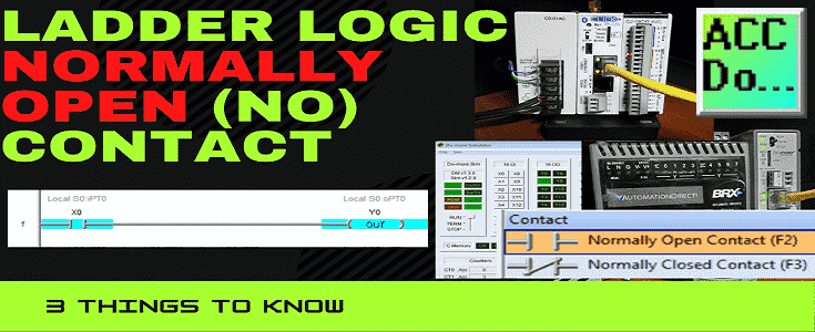
 We will be looking at three things about the normally open (NO) contact on our ladder logic program. The normally closed NC ladder logic contact will also be discussed at the end. Let’s get started.
1 – Ladder Logic NO Contact Condition
The ladder logic normally open (NO) provides a condition on the ladder logic rung. Ladder logic rungs usually consist of 1 or more input conditions that must be active to turn on the output. When engaged, on or 1, this rung input will allow the rung to be active at that point.
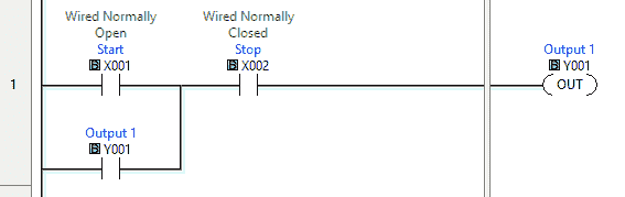
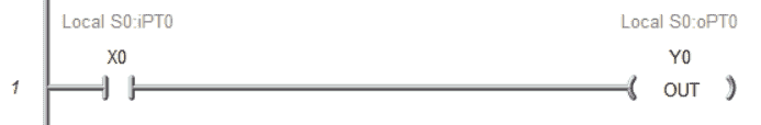 This sample rung has one normally open contact and one output. The input NO condition is not active, so the output is not active or on.
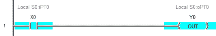 When the NO contact is activated on this rung, all conditions are met, and the output is activated.
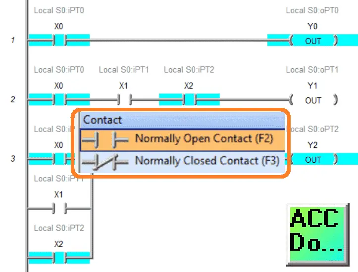
You can add contact inputs on the ladder rung in series (AND) or parallel (OR).
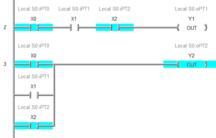 Here is an example of series and parallel contacts or inputs on a rung.
Watch the video below to see this in action.
2 – Ladder Logic NO Contacts are Just Memory Bits
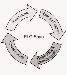
The normally open contact input on the ladder logic is just a memory bit within the PLC. A cyclic scan of the PLC consists of reading the inputs, solving the logic, diagnostics & communication, and setting the outputs.
 The reading of the inputs will transfer the information to internal memory bits. This means that the ladder logic program can manipulate its value.
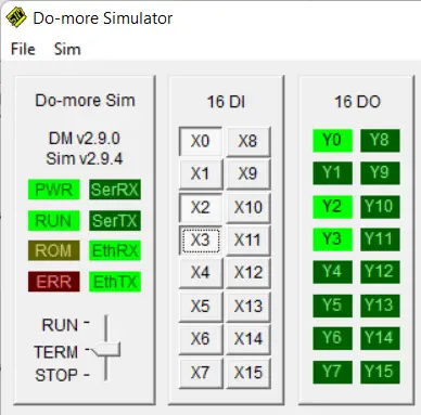
Take a look at the following ladder rungs. What will happen with outputs Y3 and Y4 when NO contact X3 turns on?
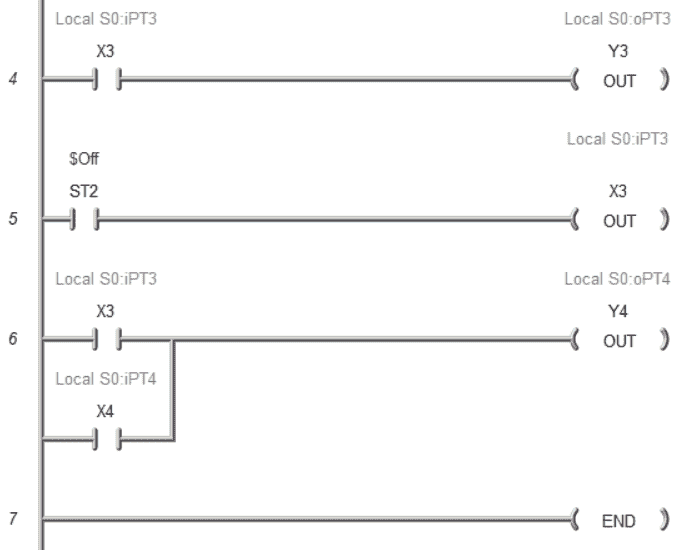 Rung 4 will turn on Y3 when X3 turns on. X3 (internal bit) is turned off by rung five and the always off bit. Y4 does not turn on when X3 is physically turned on because we changed the bit in the previous rung.
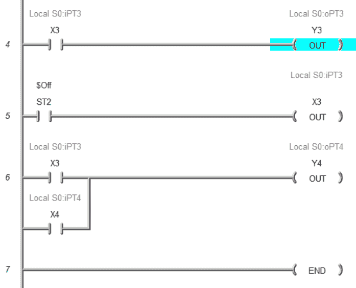 You will notice that the X3 input does not show as being energized or on when viewing the ladder logic. This is because the logic has turned this bit off. The scan will still read the physical input as being on and copy this to the memory location to activate Y3 but then turns the bit off.
Note: This can be hard to find when troubleshooting your logic, and you mistakenly control the physical memory bits of the inputs. Not all controllers will allow you to control these bits.
The first two things to know about NC contacts are using the simulator of the Do-More Designer Software.
 This fully functional free software will allow you to try your programs without purchasing hardware. The simulator will communicate Modbus TCP and MQTT for your SCADA or IoT applications.
Watch the video below to see the NO contact bit be changed using the ladder logic program.
3 – Ladder Logic NO Contact is not the Same as Wired Inputs
The ladder logic NO contact is not the same as wired inputs. Take a look at the following wiring diagram.
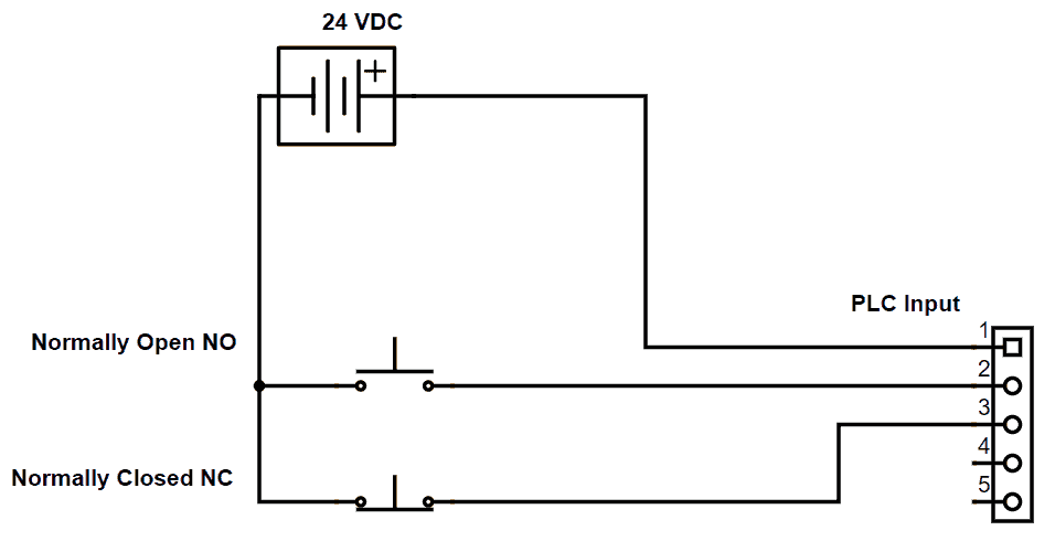 We have a normally open (NO) push button and a normally closed (NC) pushbutton wired into the PLC inputs. When nobody touches the buttons, the normally closed will provide voltage to the input of the PLC.
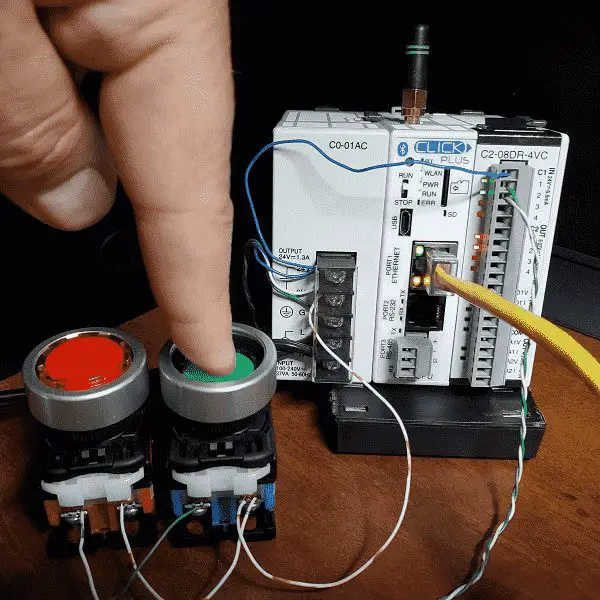
 Here is our Click PLC wired as per the wiring diagram. X1 is our NO pushbutton, and X2 is our NC pushbutton. You will notice that X2 is on or active because the voltage is present in the normally closed contact of the pushbutton. The LED will be on, indicating voltage is present on the input.
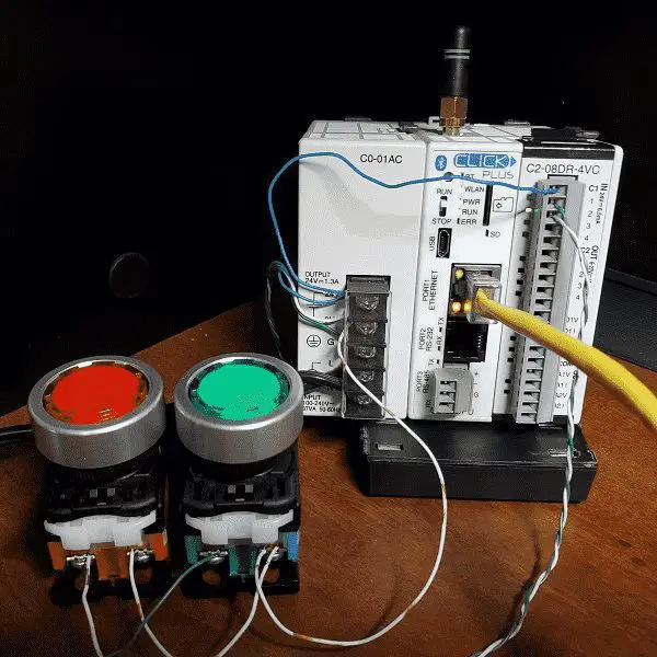
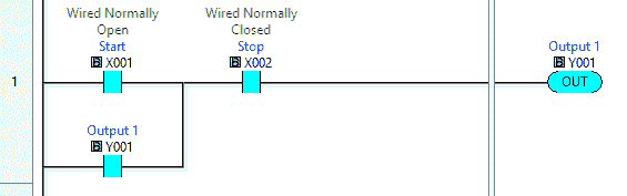
 Here is a Click PLC start-stop latching circuit with a sealing contact. X2 is already active because we have the input active because of the NC wiring.
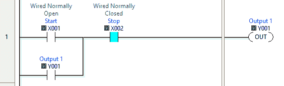
Looking at a start-stop circuit in the PLC, you will notice that the stop input is a normally open contact on the ladder logic. The input is wired to the PLC as a normally closed contact. We want to use this normally closed contact to stop our output when selecting the push button. Think of the ladder logic normally open contact as examining the input and determining what the condition is based on the voltage input.
 Pressing the start pushbutton will active X1.
 The ladder logic will turn on or activate X1, which will turn on the output Y1.
 When the NO pushbutton is released, Y1 output is used as a latch to keep it on.
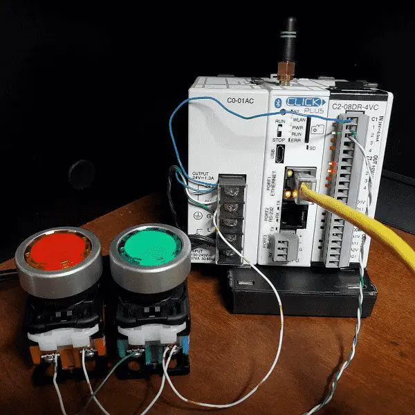 You can see that the LED is on for our output Y1 in our Click PLC.
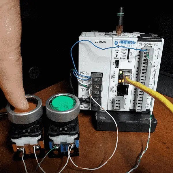 Pressing the NC stop pushbutton will turn off our input X2.
 The ladder logic NO X2 will turn off, causing output Y1 to turn off.
Releasing the stop pushbutton will bring us back to our original ladder logic state.
Watch the video below to see the wired vs ladder logic contacts in action.
4 – Ladder Logic Normally Closed (NC) Contact
The last things apply to the ladder logic NC contact. It is just the opposite of the ladder logic NO contact.
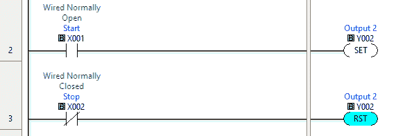 Look at this start-stop circuit using the set and reset instructions. We use a normally closed ladder logic contact because the input signal is wired NC. If we did not, X2 would be on all the time, and the reset instruction would always be active.
This can be confusing, especially in troubleshooting the PLC. Always refer to how the signals are wired to the PLC to clarify how the ladder logic rung is being solved. How have you handled this in your applications? Let me know in the comments below.
Here is a post on how to make a start-stop jog circuit in a PLC. This will show the NO contacts and give you an understanding of the PLC scan for the jog input.
Download the PLC ladder logic program files here.
Watch below to see what you should know about ladder logic normally open (NO) contacts.
Free learning and training series for PLCs.
Click / Click PLUS (Koyo)
BRX Do-More
Productivity Series
P1000
P2000
C-More EA9 Series of HMI
(Webserver, FTP, Data Logging, Free Remote Apps, etc.)
Node-Red is a free IoT software hub that can communicate MQTT and many standard industrial protocols. This series will help you communicate to the PLC, create an HMI on any electronic device, log data to a database, and view the information on a spreadsheet for analysis.
Node-RED IoT enabling Software
Watch on YouTube: Ladder Logic Normally Open (NO) Contact – 3 Things to Know
If you have any questions or need further information, please contact me.
Thank you,
Garry
If you’re like most of my readers, you’re committed to learning about technology. Numbering systems used in PLCs are not challenging to learn and understand. We will walk through the numbering systems used in PLCs. This includes Bits, Decimal, Hexadecimal, ASCII, and Floating Point.
To get this free article, subscribe to my free email newsletter.
Use the information to inform other people how numbering systems work. Sign up now.

The ‘Robust Data Logging for Free’ eBook is also available for free download. The link is included when you subscribe to ACC Automation.