The freight carrier weighing and distribution will demonstrate sequencing and shift registers on the EasyPLC machine simulator. The product comes in two different ways and must be organized, weighed, and delivered on the right output ramp. This will be based on the weight of the product. The EasyPLC simulator freight carrier will show you how you can control this process through a programmable logic controller. Learning PLC programming can sometimes be challenging, but EasyPLC allows you to practice and learn your ladder logic skills on the controller of your choice. It is the best method of learning industrial control PLC programming.
 Using the five steps for PLC program development, we will discuss and show you how to program this freight carrier weighting and distribution simulator. An Automation Direct Click PLC will be used for this application, but the general methods can be used for just about any PLC on the market. This PLC simulator will show you sequencing and shift registers programming. Let’s get started.
Learn PLC programming the easy way. See below how to receive a 10% discount on this already cost-effective learning tool. Invest in yourself today.
Previously we have done the following:
Easy PLC Installing the Software – Video
EasyPLC Software Suite – Quick Start – Video
Click PLC – Easy Transfer Line Programming – Video
Productivity PLC Simulator – Chain Conveyor MS – Video
Do-More PLC – EasyPLC Box Selection Program – Video
Click PLC EasyPLC Gantry Simulator – Video
Click PLC Simple Conveyor EasyPLC – Video
EasyPLC Paint Line Bit Shift – BRX Do-More PLC – Video
Click PLC – EasyPLC PLC Mixer Programming – Video
Click PLC EasyPLC Warehouse Stacker Example – Video
– Operation Video
EasyPLC Machine Simulator Productivity PLC Robotic Cell – Video
EasyPLC Simulator Robotic Cell Click PLC – Video
EasyPLC Simulator Robotic Cell BRX Do-More PLC – Video
– EasyPLC Factory Editor Robotic Cell Additions Video
4 Way Traffic Light PLC Program EasyPLC – Video
Rock Crusher Plant EasyPLC BRX Do-More – Video
Define the task: (Step 1 – EasyPLC Freight Carrier)
The first step of PLC program development is determining what must be done.
Distribute the goods along the conveyor line managing the tables to prioritize each entry line. The goods have to be weighed in the balance system. The exit ramps must send the boxes according to the following criteria:
Ramp 1 – Boxes of 20 Kg weight
Ramp 2 – Boxes of 15 Kg weight
Ramp 3 – Boxes of 10 Kg weight
Ramp 4 – Boxes of 5 Kg weight or less
The EasyPLC software suite contains this freight carrier example in the machine simulator.
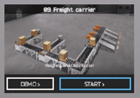
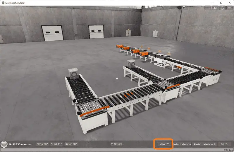
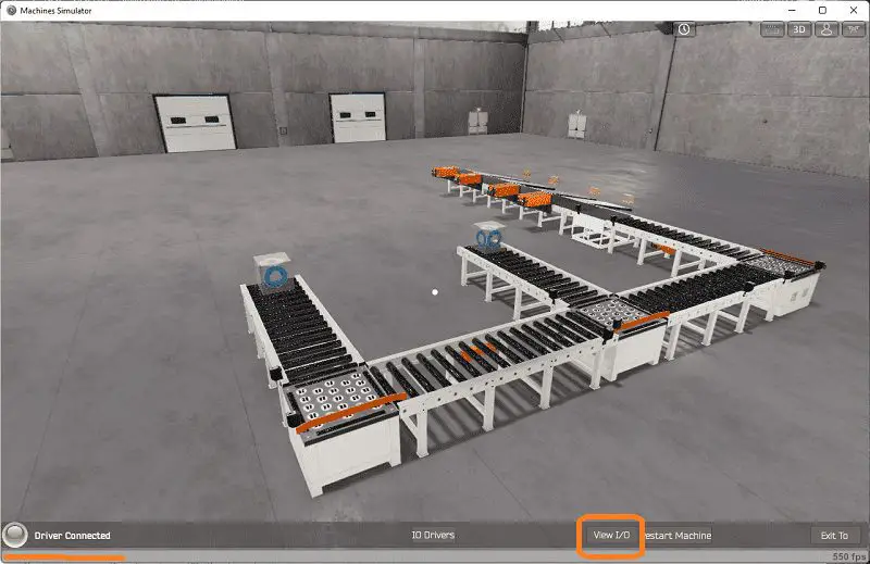
Start the EasyPLC Machine Simulator (MS). Select the start button on the main page or select machines from the main menu on the top of the machines simulator window.
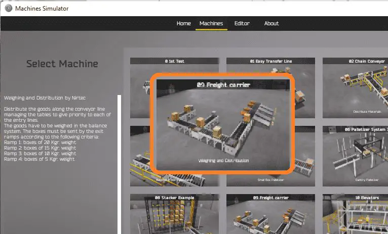 All the available machines will now be displayed. Click on the “09 Freight carrier Weighing and Distribution”.
This is the example that we will be programming. To the left of the screen, information will be displayed on how the freight carrier needs to function.
This is printed above.
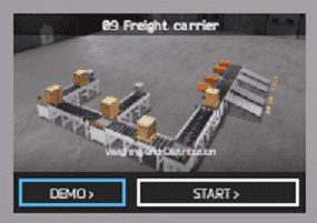 The machine simulator has a demo mode for the built-in machines. This will allow you to watch the operation of the freight carrier. Select the demo mode.
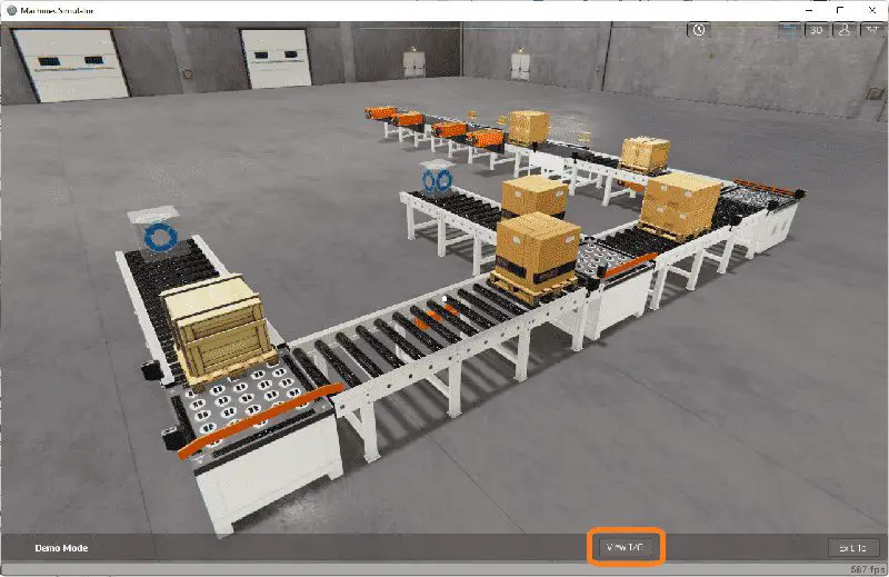 The freight carrier demo mode on the machine simulator will operate, showing you the basics of operation.
Move around the 3D virtual environment. Three icons on the top of the window will allow you to move around this 3D environment. The first icon is the default selection. This will enable you to move around without bumping into the components. The first-person mode will mimic a person in your 3D learning world. The last icon will automatically show you around this virtual environment. Once we understand what must be done, we can move on to the next step in our PLC program development.
Define the Inputs and Outputs: (Step 2 – EasyPLC Freight Carrier)
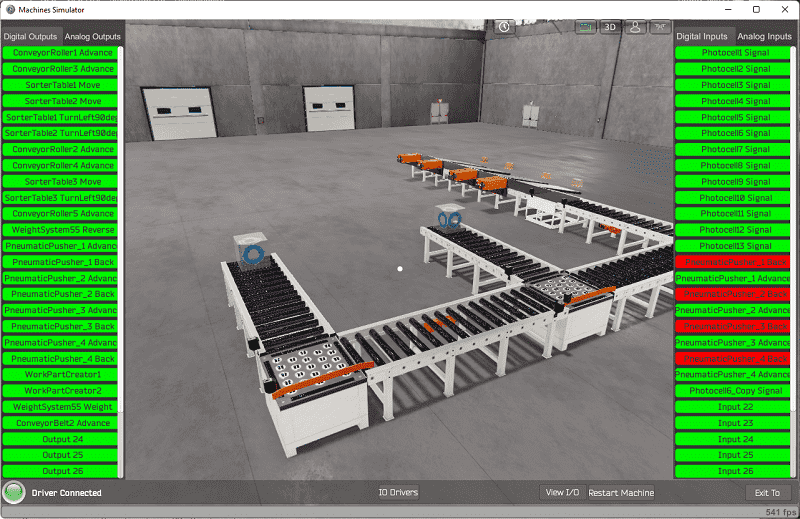
The View IO at the bottom of the machine simulator window will display the inputs and outputs required for this freight carrier example. While still in demo mode, you can see the operation of the inputs and outputs.
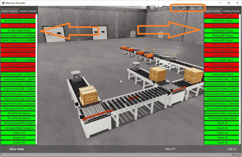 The EasyPLC freight carrier example will require 24 digital outputs and 22 digital inputs. It will also need an analog input for the weighing system.
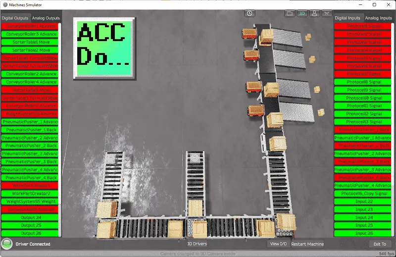
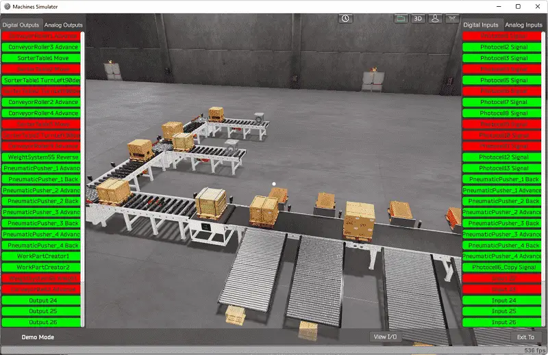 The EasyPLC start mode will allow you to control the freight carrier simulator manually.
 This is ideal if you are unsure what outputs or inputs are doing.
 Select the View IO on the bottom middle of the machine simulator window. You can manually run the robotic cell without any control or PLC connected.
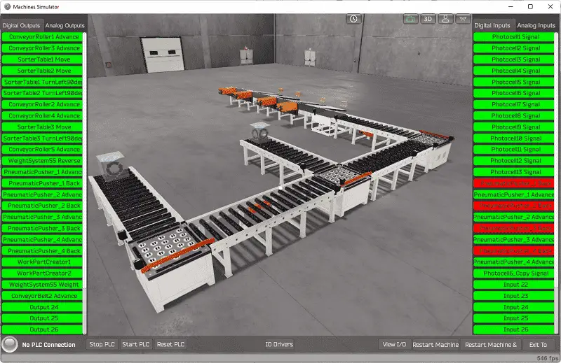 You can now use select and start the freight carrier digital outputs on the left side of the screen by clicking on them with the mouse. The right side will show you the corresponding digital inputs. The restart button on the bottom of the machine simulator window will reset the scene back to the start.
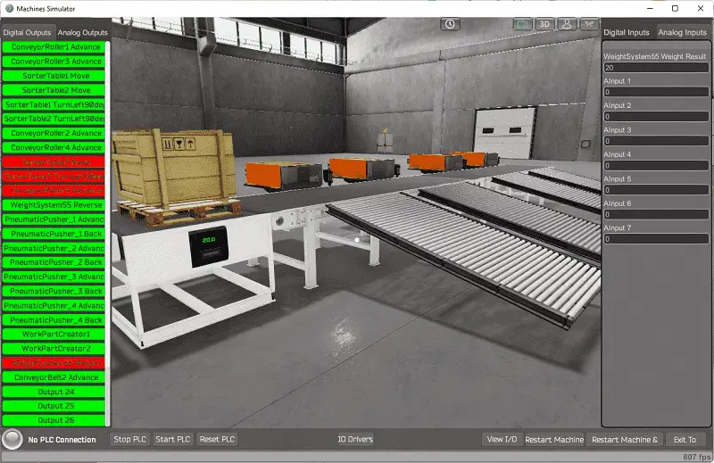
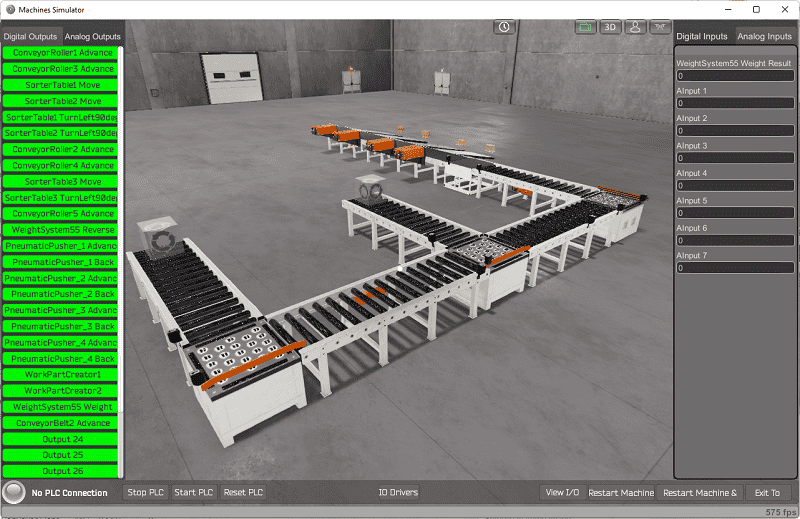 Selecting the analog inputs on the right-hand side will display the weight system analog input.
 The following table will define the inputs and outputs (IO) and Modbus addresses in the Click PLC that we will be using for this program.
| Digital Type | Description | Click PLC Modbus Address | Machine Simulator Modbus Address |
| PLC Output – MS Input | Conveyor Roller 1 Adv | C101 – 16485 | 16484 |
| PLC Output – MS Input | Conveyor Roller 3 Adv | C102 – 16486 | 16485 |
| PLC Output – MS Input | Sorter Table 1 Move | C103 – 16487 | 16486 |
| PLC Output – MS Input | Sorter Table 2 Move | C104 – 16488 | 16487 |
| PLC Output – MS Input | Sorter Table 1 Left 90 | C105 – 16489 | 16488 |
| PLC Output – MS Input | Sorter Table 2 Left 90 | C106 – 16490 | 16489 |
| PLC Output – MS Input | Conveyor Roller 2 Adv | C107 – 16491 | 16490 |
| PLC Output – MS Input | Conveyor Roller 4 Adv | C108 – 16492 | 16491 |
| PLC Output – MS Input | Sorter Table 3 Move | C109 – 16493 | 16492 |
| PLC Output – MS Input | Sorter Table 3 Left 90 | C110 – 16494 | 16493 |
| PLC Output – MS Input | Conveyor Roller 4 Adv | C111 – 16495 | 16494 |
| PLC Output – MS Input | Weight System 55 Reverse | C112 – 16496 | 16495 |
| PLC Output – MS Input | Pneumatic Pusher 1 Adv | C113 – 16497 | 16496 |
| PLC Output – MS Input | Pneumatic Pusher 1 Back | C114 – 16498 | 16497 |
| PLC Output – MS Input | Pneumatic Pusher 2 Adv | C115 – 16499 | 16498 |
| PLC Output – MS Input | Pneumatic Pusher 2 Back | C116 – 16500 | 16499 |
| PLC Output – MS Input | Pneumatic Pusher 3 Adv | C117 – 16501 | 16500 |
| PLC Output – MS Input | Pneumatic Pusher 3 Back | C118 – 16502 | 16501 |
| PLC Output – MS Input | Pneumatic Pusher 4 Adv | C119 – 16503 | 16502 |
| PLC Output – MS Input | Pneumatic Pusher 4 Back | C120 – 16504 | 16503 |
| PLC Output – MS Input | WorkPartCreator1 | C121 – 16505 | 16504 |
| PLC Output – MS Input | WorkPartCreator2 | C122 – 16506 | 16505 |
| PLC Output – MS Input | Weight System 55 Operate | C123 – 16507 | 16506 |
| PLC Output – MS Input | Conveyor Belt 2 Advance | C124 – 16508 | 16507 |
| PLC Input – MS Output | Photocell 1 Signal | C201 – 16585 | 16584 |
| PLC Input – MS Output | Photocell 2 Signal | C202 – 16586 | 16585 |
| PLC Input – MS Output | Photocell 3 Signal | C203 – 16587 | 16586 |
| PLC Input – MS Output | Photocell 4 Signal | C204 – 16588 | 16587 |
| PLC Input – MS Output | Photocell 5 Signal | C205 – 16589 | 16588 |
| PLC Input – MS Output | Photocell 6 Signal | C206 – 16590 | 16589 |
| PLC Input – MS Output | Photocell 7 Signal | C207 – 16591 | 16590 |
| PLC Input – MS Output | Photocell 8 Signal | C208 – 16592 | 16591 |
| PLC Input – MS Output | Photocell 9 Signal | C209 – 16593 | 16592 |
| PLC Input – MS Output | Photocell 10 Signal | C210 – 16594 | 16593 |
| PLC Input – MS Output | Photocell 11 Signal | C211 – 16595 | 16594 |
| PLC Input – MS Output | Photocell 12 Signal | C212 – 16596 | 16595 |
| PLC Input – MS Output | Photocell 13 Signal | C213 – 16597 | 16596 |
| PLC Input – MS Output | Pneumatic Pusher 1 Ret | C214 – 16598 | 16597 |
| PLC Input – MS Output | Pneumatic Pusher 1 Fwd | C215 – 16599 | 16598 |
| PLC Input – MS Output | Pneumatic Pusher 2 Ret | C216 – 16600 | 16599 |
| PLC Input – MS Output | Pneumatic Pusher 2 Fwd | C217 – 16601 | 16600 |
| PLC Input – MS Output | Pneumatic Pusher 3 Ret | C218 – 16602 | 16601 |
| PLC Input – MS Output | Pneumatic Pusher 3 Fwd | C219 – 16603 | 16602 |
| PLC Input – MS Output | Pneumatic Pusher 4 Ret | C220 – 16604 | 16603 |
| PLC Input – MS Output | Pneumatic Pusher 4 Fwd | C221 – 16605 | 16604 |
| PLC Input – MS Output | Photocell 6 Copy Signal | C222 – 16606 | 16605 |
| PLC Analog Input – MS Analog Output | Weight Scale Reading | DS111 – 400111 | 400110 |
Note: The machine simulator will be offset by one on the Modbus Addresses. See the video below for the demo mode and determining inputs and outputs.
See the video below for the demo mode and determining inputs and outputs.
Develop a logical sequence of operation: (Step 3 – EasyPLC Freight Carrier)
A PLC programmer must know how everything about the sequence and operation of the machine before programming. The rock crusher plant is an excellent way to learn to program. A flow chart or sequence table is used to understand the process that must be controlled thoroughly. It must also answer questions like the following:
What happens when electrical power and pneumatic air is lost? What happens when the input/output devices fail? Do we need redundancy?
This step is where you will spend most of your time. Understanding everything about the operation will save you time. It will help prevent you from continuously re-writing the PLC program logic. Knowing all these answers to how the system is to react is vital in developing the PLC program.
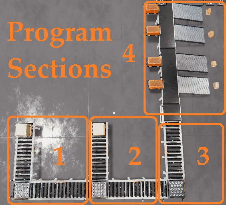
Our freight carrier machine is split up into four different sections. We will walk through the logical sequence of operation.
Splitting the requirements up into smaller sections will allow you to concentrate on the task and not get distracted by other parts of the program that are unrelated.
A start-up timer of 5 seconds will be used when the machine starts so that all conveyor boxes will be moved to the end of the conveyor lines. This will be common to all of the different sections.
The first section will deal with conveyors 1, 2, and table 1. It will also create a part on the conveyor if nothing is detected at the end of the conveyor. When this section is running and complete, a box will be at the end of the conveyors and on the table. If a box is on the back of the conveyor one and no box is seen on the table, then the box is moved to the table. When a box is on the table and nothing is on the end of conveyor 2, then the box will move to the end of conveyor 2.
Section 2 will be similar control to section 1. This will control conveyors 3, 4, and table 2. Table 2 will alternate getting a box from conveyor two and then conveyor 3.
Section 3 will control table 3 and conveyor 5. If a box is present on conveyor four and no box is on table 3, it will be moved onto the table. If a box is on the table and not at the end of conveyor 5, the box will be transferred to the end of conveyor 5.
Section 4 will control the weight station and exit ramps. When no box is detected on the weigh station, the box at the end of conveyor five will be moved into the station. Then the box is seen at the station; a timer is used for 2 seconds to allow the weight to be read.
Depending on the weight read, a shift register is enabled for the exit ramp. Our example will have three shift registers to track the first three exit ramps. The last ramp will be the smallest weight and will reject everything detected in front of it. Usually, a shift register will track parts by a mechanical gear on the conveyor belt. In our case, we will be using a time pulse bit of 500 milliseconds. The sensor beside each of the reject cylinders will ensure that our timing for the reject is accurate.
A PLC programmer must know how everything about the sequence and operation of the machine before programming.
Ask questions or View existing documentation to ensure that you know the logical steps to the machine operation. Writing out what is supposed to happen will help clarify what is required in the PLC program. This is just another method like flow charts and sequence tables.
Develop the Click PLC program: (Step 4 – EasyPLC Freight Carrier)
A programmable logic controller (abbreviated PLC) is an industrial computer programmed to perform various automated tasks based on multiple inputs and outputs. They are commonly used in manufacturing, construction, energy distribution, and process control applications. In basic terms: – The ladder logic programming language is used to instruct its function and operations that must be taken when a specific condition arises. Using the information from the previous step, we can now program our Click PLC freight carrier. The Click PLC Series will take you through installing the program, communicating to the controller instructions, and addressing the controller.
Sample Program – Click PLC
Freight Carrier Weighing and Distribution EasyPLC
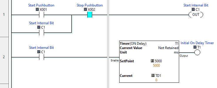 Start / Stop System – Pushbutton switches are hardwired into the inputs of the Click PLC.
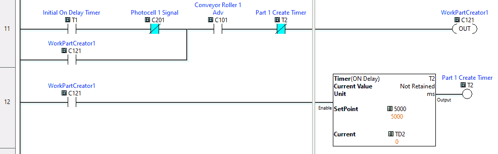
C1 will act as a master bit for the program. Timer 1 will have an On-Delay time to move any boxes on the conveyors to the ends during the initial start-up of the freight carrier application.
Section 1
During the initialization stage, conveyor 1 will turn on and ensure that the sorter table is reset. When the initialization stage is done then the conveyor 1 will be set once a box is required on the first table. It will turn off when the leading edge of the photocell 1 is on.
The sorter table will turn 90 degrees when the photocell signal is on. It will reset once the box has reached the end of conveyor 2.
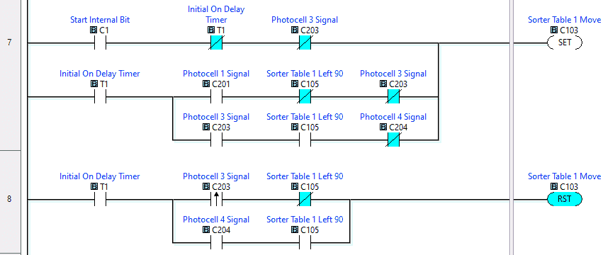
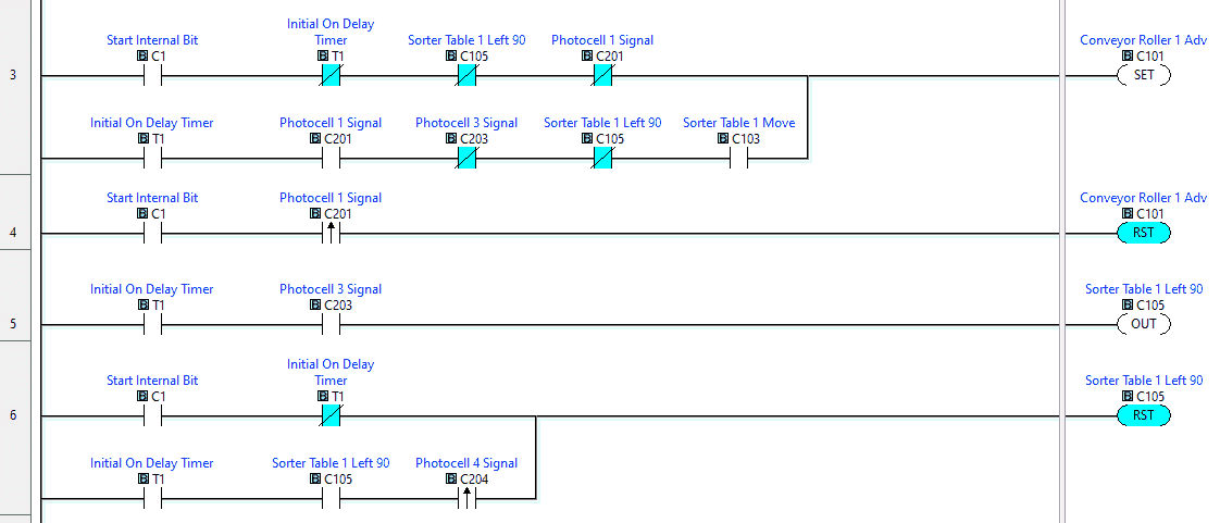 The sorter table 1 move will be on during initialization. When this is done then it will be on when we have a box at the end of conveyor 1 and nothing on the table. It will also be on when we have a box on the table and nothing at the end of conveyor 2.
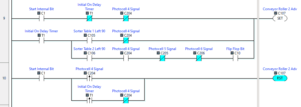
 Conveyor 2 moves the boxes from table 1 to the end of the conveyor. It will also transfer the box to table 2. A flip flop bit will control when to move the box to the table.
 The work part creator 1 will be set for 5 seconds after the initialization time and if no box is at the end of conveyor 1.
Section 2
During the initialization stage, conveyor 3 will turn on and ensure that sorter table 2 is reset. When the initialization stage is done then conveyor 3 will be set once a box is required on the second table. It will turn off when the leading edge of the photocell 2 is on.
The sorter table two will turn 90 degrees when the photocell signal is on. It will reset once the box has reached the end of conveyor 4.
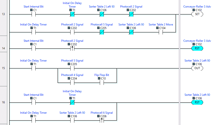 A flip flop circuit is used to toggle between the two different paths the box can arrive onto the sorter table two.
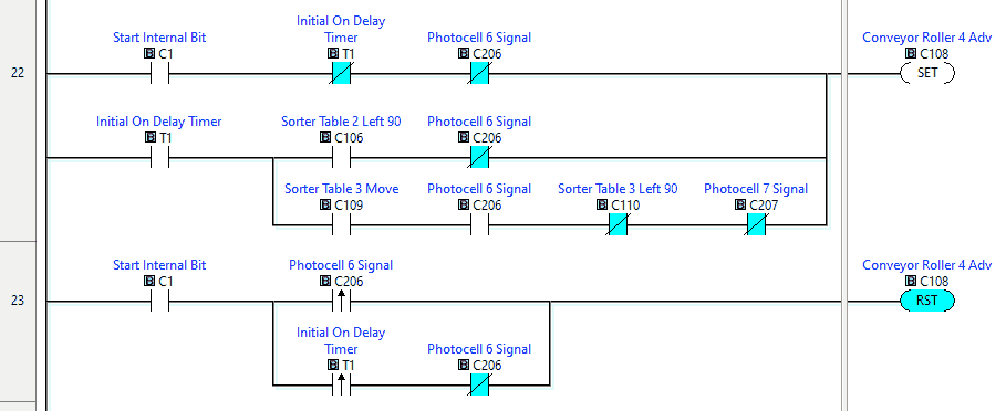
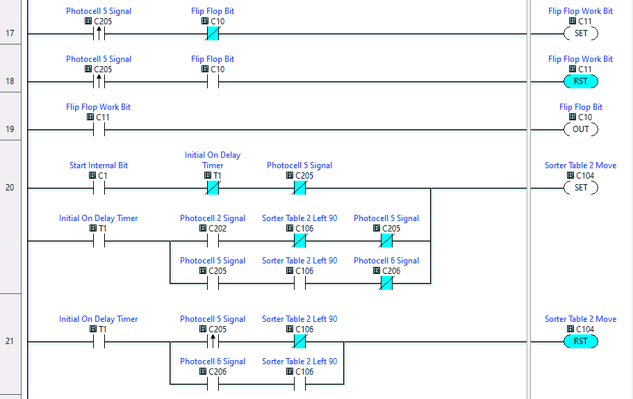 Conveyor 4 moves the boxes from table 2 to the end of the conveyor. It will also transfer the box to table 3.
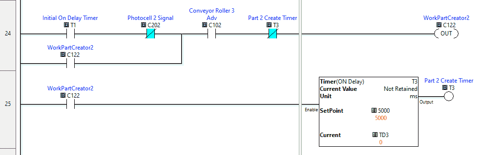
 The work part creator 2 will be set for 5 seconds after the initialization time and if no box is at the end of conveyor 3.
Section 3
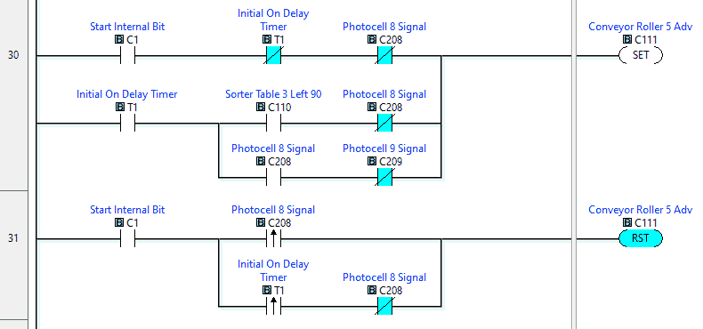
This will control conveyor 5 and roller table 3.
The roller table will move the box from conveyor 4 to the roller table. The table will rotate and wait for conveyor 5 to be empty before moving the box.
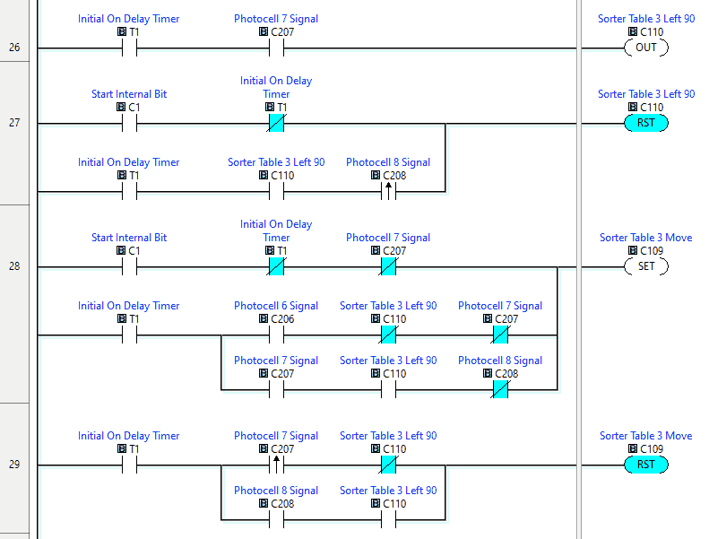 If no product is on conveyor 5 then the box on table 3 is transferred. If no product is on the weight scale, then the box is transferred to the weigh scale.
Section 4
This section will weight and distribute the boxes to the exit ramps.
If no box is present on the weight scale the conveyor will start and bring in a box until the sensor is seen.
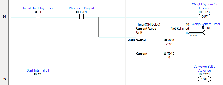
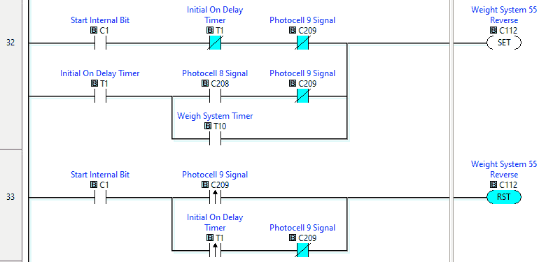 When a box is on the weigh scale, the weight system operate will start and a timer is started. When the timer expires the box is then transferred to conveyor belt 2 which will send the box to the ramps.
 Ramp 1
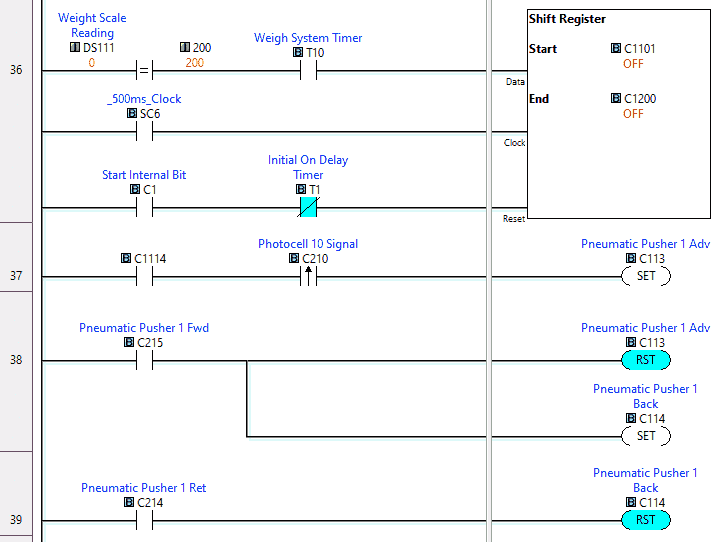
If the box weight scale reading is 20.0 Kgs then a shift register is loaded for the first ramp. The timing of the shift register is from a 0.5-second pulse bit.
When the box is in front of the exit ramp and the shift register indicates that the box is the correct weight, pusher 1 will advance. It will automatically retract when it sees the extended input.
 Ramp 2
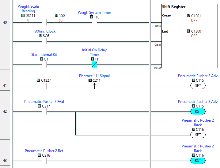
If the box weight scale reading is 15.0 Kgs then a shift register is loaded for the second ramp. This is a separate shift register from the first. The timing of the shift register is from a 0.5-second pulse bit.
When the box is in front of the exit ramp and the shift register indicates that the box is the correct weight, pusher 2 will advance. It will automatically retract when it sees the extended input.
 Ramp 3
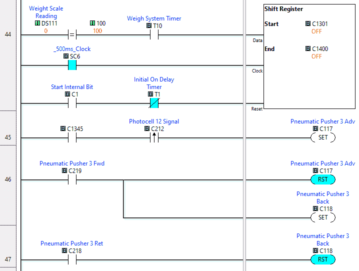
If the box weight scale reading is 10.0 Kgs then another shift register is loaded for the third ramp. The timing of the shift register is from a 0.5-second pulse bit.
When the box is in front of the exit ramp and the shift register indicates that the box is the correct weight, pusher 3 will advance. It will automatically retract when it sees the extended input.
 Ramp 4
If the box weight scale reading is 5.0 kg or less the boxes are allowed to pass the other exit ramps. When the box is in front of the last exit ramp pusher 4 will advance. It will automatically retract when it sees the extended input.
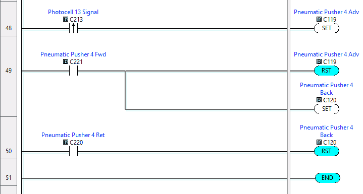 This is our completed PLC ladder logic code for the EasyPLC freight carrier.
We will now set up the communication port on the Click PLC for the EasyPLC freight carrier. Modbus TCP will be used with the Ethernet port of the Click PLC.
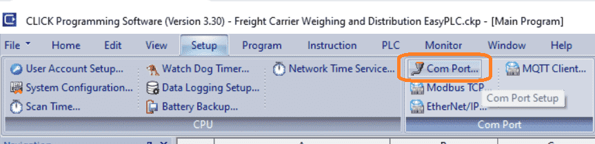 Select the Com Port under setup on the main menu. You can also call this up by selecting system configuration and clicking on the ports of the click picture.
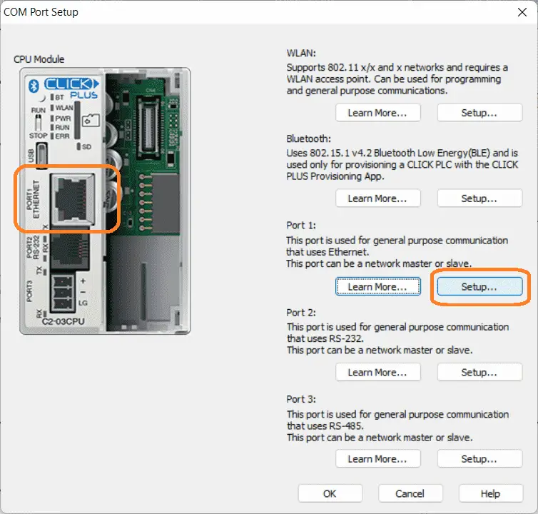 Select the setup button on the COM Port Setup window.
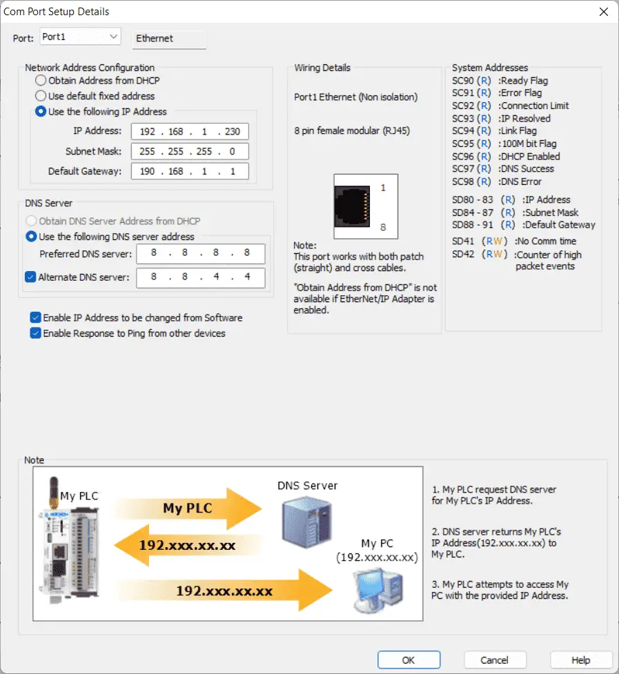 We will use a static IP address for the Ethernet port. Here are our settings for the Ethernet port.
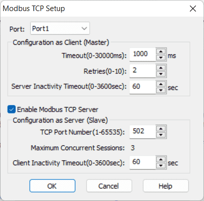 Select Modbus TCP to ensure that the enable Modbus / TCP Server is selected. This is on by default, with port 502 as the default number. Everything is left as the default. We can change some of these settings if communication can not be established reliably. Our PLC is now a Modbus TCP Server to the EasyPLC Modbus TCP Client. Please make a note of the static IP address that we are using for the Click PLC. This will be used later to connect to the EasyPLC machine simulator.
Download the program to the Click PLC. Ensure that the controller is in run mode.
Watch the video below to see this Click PLC program in action operating the EasyPLC freight carrier.
Test the program: (Step 5 – EasyPLC Freight Carrier)
We will be using Modbus TCP on our Click PLC to communicate to the EasyPLC Machine Simulator.
Call up the EasyPLC freight carrier in start mode.
 The status of the machine simulator will be along the bottom of the screen. Currently, we have no PLC connected. Select IO Drivers on the bottom middle of the screen.
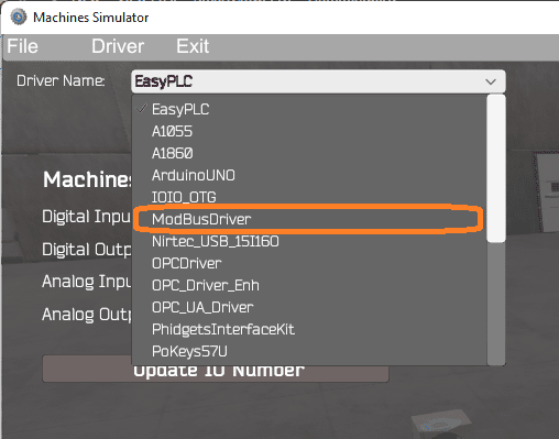 The EasyPLC driver is selected by default. Under the driver pull-down menu, select “ModBusDriver.” This driver will communicate Modbus TCP (Ethernet) and Modbus RTU (Serial). Select the down arrow on the driver’s name.
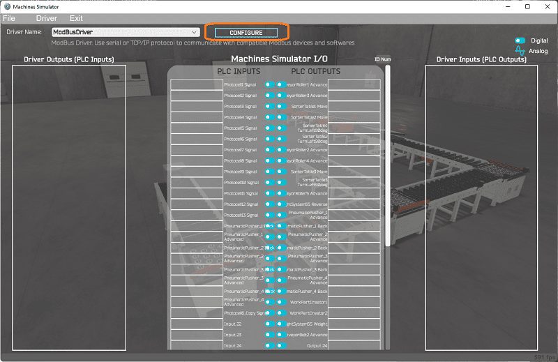 Select the configure button.
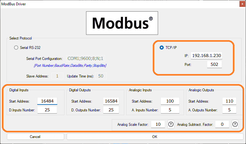 We can now enter the information for our Modbus driver. Select TCP/IP. This means the Ethernet port on the computer will communicate to the PLC.
The digital inputs from MS to the Click PLC will be C101 to C124. This will start at address 16484 because of the offset of 1. Digital outputs from MS to the Click PLC will be C201 to C222. This will start at address 16584 because of the offset of 1. Select the OK button.
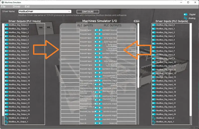 You will now see the inputs and outputs specified for the Modbus driver. We can manually assign the driver outputs to the PLC inputs and the driver inputs to the PLC outputs. However, the automatic assignment works well and will save you time.
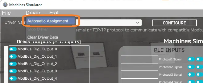 Select Automatic Assignment from the driver option in the main menu.
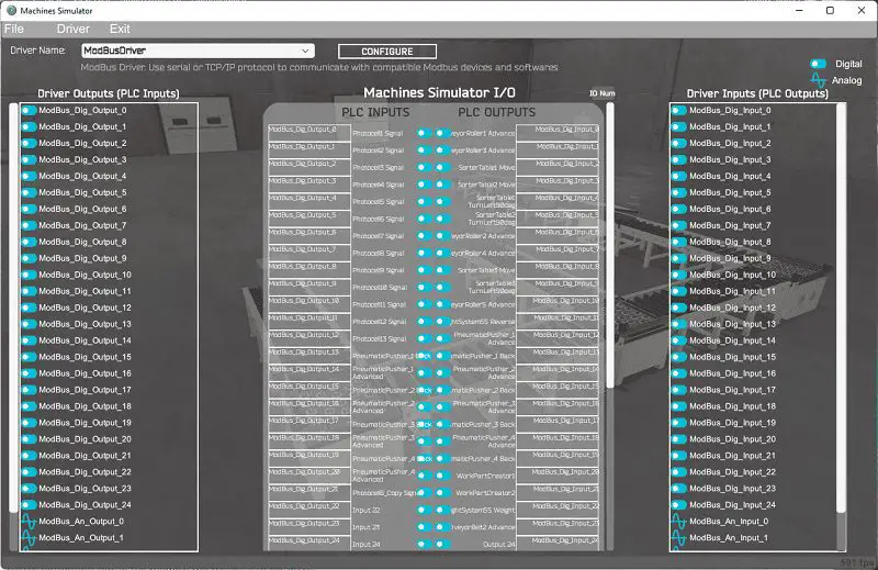 This will automatically assign the PLC IO to the Machine Simulator IO.
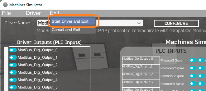 Select start driver and exit from the main menu.
 On the bottom left side of the window, you will see that the driver communicates to the PLC by the green light. Select view IO to know the input and output status of the machine simulator.
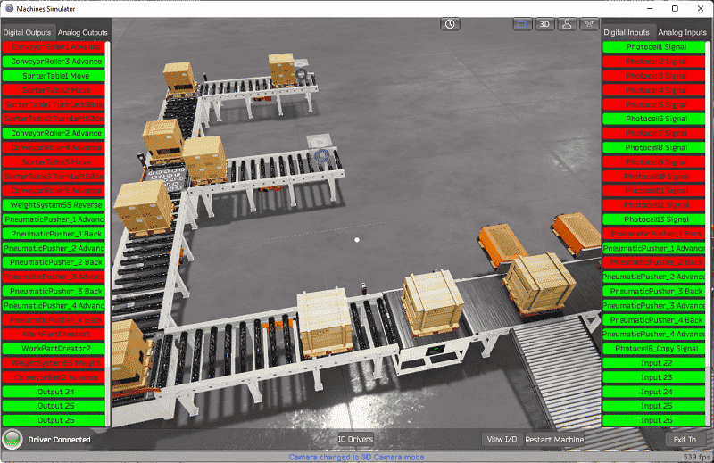
 Ensure that the PLC is in run mode. Press the start push button and start the EasyPLC freight carrier. We can see the operation of our simulation.
 Move around the environment to see at different angles.
 Using the Data View window of the Do-More Designer programming software, we can also watch the inputs and output operations.
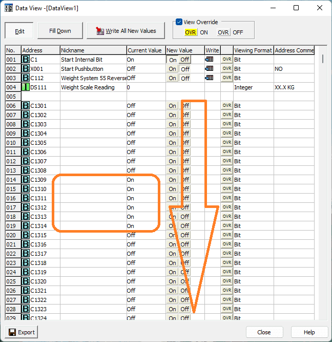 Here are the bits in the shift register for ramp 3. You can see the bits being shifted down as the box moves along the conveyor belt.
Watch the video below to see this on the operation.
If your program works correctly, it’s time to move on. If not, you’ll need to debug. This can be as simple as re-downloading and re-uploading your program or as complicated as redesigning your logic altogether. When using EasyPLC, debugging is quickly done with no damage to any equipment. You may modify your logic several times before you get everything right! That’s okay—it’s all part of learning to program PLCs. After all: trial and error are often easier said than done! To learn more about developing logic, check out our tutorials on the five steps to PLC program development.
You can practice your modification and debug by modifying the EasyPLC freight carrier in the following way:
– Add a control panel to the EasyPLC freight carrier. This will allow you to stop and stop the operation. Also, keep track of the number of boxes on each exit ramp.
– Is this the most efficient way to do this application? See if you can improve the throughput time of the boxes.
Let me know how you make out in the comments below.
Download the Click PLC sample program here.
Watch the video below to see the five steps of program development applied to the freight carrier. The machine simulator is one of the best applications to help you learn PLC programming.
EasyPLC Software Suite is a complete PLC, HMI, and Machine Simulator Software package. This PLC learning package includes the following:
Easy PLC – PLC Simulation allows programming in Ladder, Grafcet, Logic Blocks, or Script.
HMI System – Easily create a visual human-machine interface (HMI)
Machine Simulator – A virtual 3D world with real-time graphics and physical properties. PLC programs can be tested using the EasyPLC or through other interfaces. (Modbus RTU, TCP, etc.)
Machine Simulator Lite – Designed to run on Android Devices.
Machine Simulator VR – Virtual Reality comes to life so you can test, train or practice your PLC programming.
Purchase your copy of this learning package for less than USD 75 for a single computer install or less than USD 100 to allow different computers.
Receive 10% off the price by typing in ACC in the comment section when you order. http://www.nirtec.com/index.php/purchase-price/
Learn PLC programming the easy way. Invest in yourself today.
Watch on YouTube: Freight Carrier Weighing & Distribution EasyPLC
If you have any questions or need further information, please contact me.
Thank you,
Garry
If you’re like most of my readers, you’re committed to learning about technology. Numbering systems used in PLCs are not challenging to learn and understand. We will walk through the numbering systems used in PLCs. This includes Bits, Decimal, Hexadecimal, ASCII, and Floating Point.
To get this free article, subscribe to my free email newsletter.
Use the information to inform other people how numbering systems work. Sign up now.

The ‘Robust Data Logging for Free’ eBook is also available for free download. The link is included when you subscribe to ACC Automation.