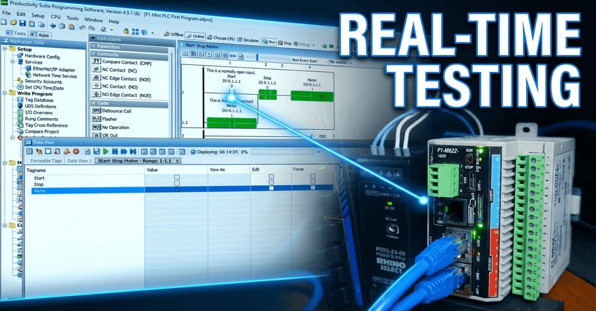
We will now look at monitoring and testing our Productivity Mini PLC program. The Productivity Suite Software provides powerful tools for us to monitor and test our programs. Last time, we created our first program—a simple start-stop motor circuit—and transferred it to our connected P1-M622-16DR Mini PLC. We will monitor our ladder using the ladder editor window and display the information in several different ways. 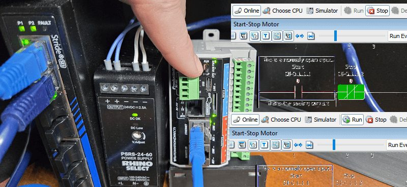
Data View is a powerful tool for testing and viewing our program. We will force the IO, toggle the IO view, and graph our tags to test our PLC logic circuit.
Let’s get started.
Previously in this Productivity Mini PLC P1-M622-16DR series, we have discussed:
P1-M622-16DR Mini PLC System Hardware – Video
Installing the Software – Video
Establishing Communication – Video
First Program – Video
Monitoring and Testing the Program – Video
Wiring and Testing – Video
Online Editing and Fail-Safe Wiring – Video
Productivity Program Monitoring – Mini PLC
Currently, we are connected to the P1 Mini PLC through our Ethernet port.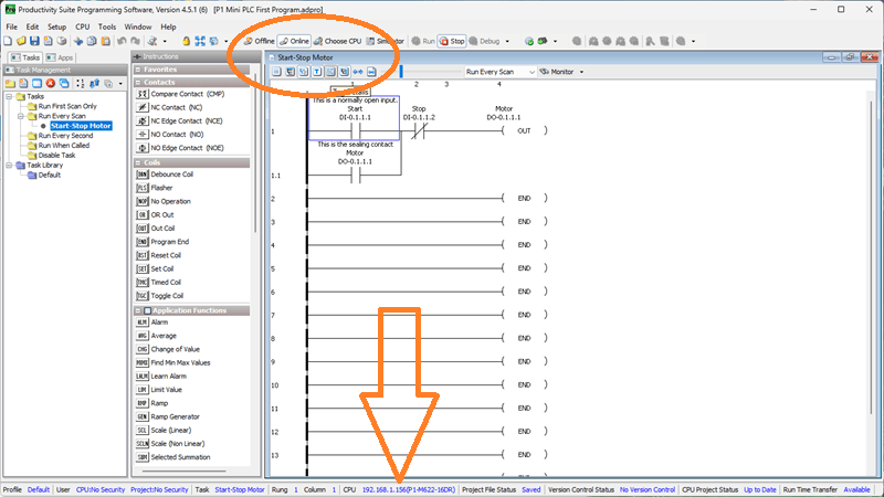
We can select the Tag Details and Instruction Comment icons on our ladder logic diagram. Select the Monitor icon on the Productivity Suite Programming software. 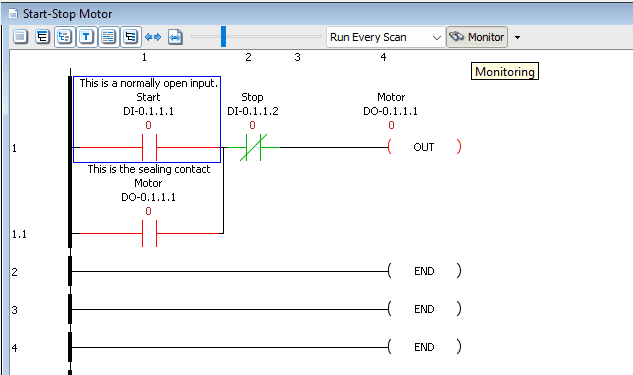
This will provide a visual indication to us on the ladder logic diagram as to the status and values of our program.
The monitoring mode on the ladder editor offers two display modes. The default shows the coils with Green (ON) or Red (OFF) line color. This may be preferable when programming and troubleshooting on a desktop.
The other monitoring mode is called Block Fill. This will reflect the states of your logic with Green (ON) fill or Red (OFF) line colour for your contacts and coils. It will make viewing the states of your logic much easier on plant floors and when monitoring the logic from a distance.
Call up the Options menu by selecting Tools | Options | Ladder tab from the main menu.
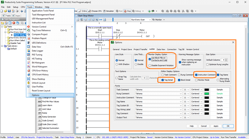
Select the Use Block Fills on Contacts and Coils under the Monitor Display Option.
Editor Display Options
While in the ladder options menu, select Rung Comment and Tag Detail under Editor Display Options. This will automatically display the documented items when we open our project.
Click Apply to change these items. Click OK to close the options window.
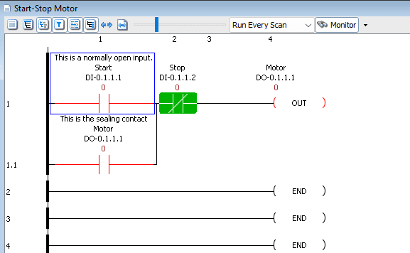
We can now see the block fill option in action. With our start-stop motor circuit loaded on the P1-M622-16DR, the contacts and coils will now show solid green when ON and red outline when OFF—making it much easier to see the logic state at a glance.
Data View – Mini PLC Monitoring Program
The Data View panel allows you to monitor and manipulate Tag values in the CPU. Multiple Data View tables (Tabs) can be made within a Data View window.
We can call the Data View panel a few different ways.
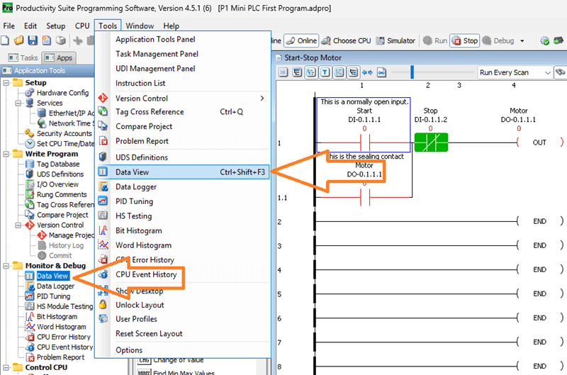
Select “Data View” from the Monitor & Debug heading under the Applications Tools.
We can also use the main menu. (Tools | Data View) The keyboard shortcut is Ctrl + Shift + F3.
Our Data View window (panel) will now show on our desktop.
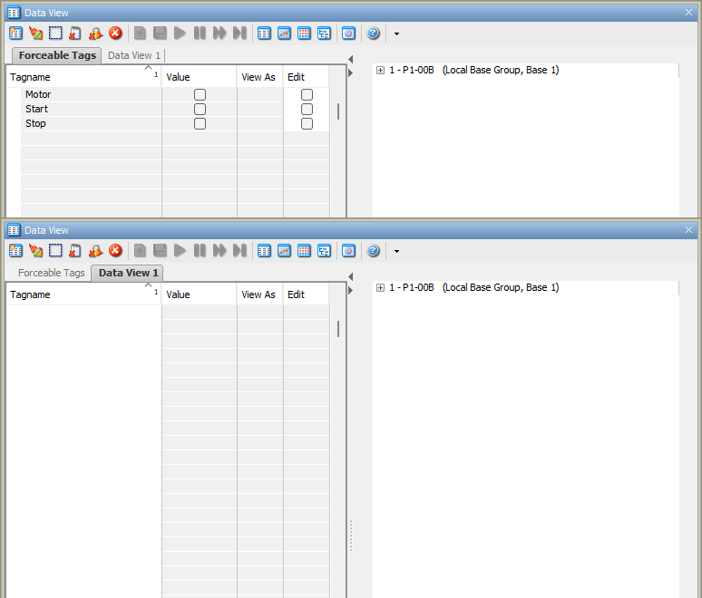
The Forceable Tags tab will be shown as the default. Some of the following parameters are shown:
Tagname – This is the name that we specified in the tag database.
Modbus Address – If a Modbus address was assigned in the tag database, it would appear here
Value – This is ON (Checked) or OFF (Unchecked)
Edit – The edit indicates the tagname to modify
Force – Forcing the tagname will either set or reset the current value of the bit
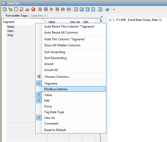
If a parameter is not shown, right-click on the headings. You can now show or hide the different parameters.
For our P1-M622-16DR Mini PLC start-stop circuit, you will see our tags:
- DI-0.1.1.1 (Start)
- DI-0.1.1.2 (Stop)
- DO-0.1.1.1 (Motor)
Our program is currently in stop mode. This is shown in the status icons at the top of our ladder logic program. Using the switch on the CPU, change it from STOP to RUN.
Forcing the IO – Mini PLC Monitoring Program
We will force the Start bit by checking the Force.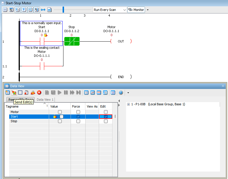
You will notice the lock next to the value. This indicates that the bit is forced. The actual input status does not matter. The force of the bit (on or off) will override.
Click the Edit. This will instruct the software to change the status from on to off or off to on, depending on the current state of the bit being forced. In our case, the bit is off, so we want to force it on.
Clicking the Send Edit(s) icon will now set the force on the selected bit (Start).
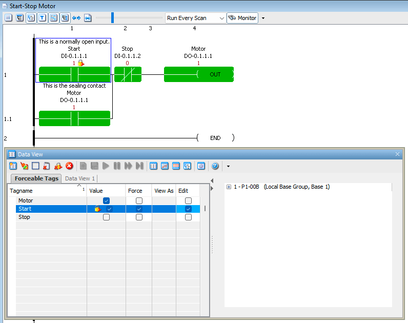
Our program will now display the forced bit, indicated by the lock icon, next to the contact. With the Start input forced ON, you will see:
- The Start contact (DI-0.1.1.1) turns green with a lock icon
- The Motor output (DO-0.1.1.1) turns ON and seals in
- The physical relay output on the Mini PLC energizes
Selecting the Edit bit again for the Start and clicking the Send Edit(s) will force the bit off.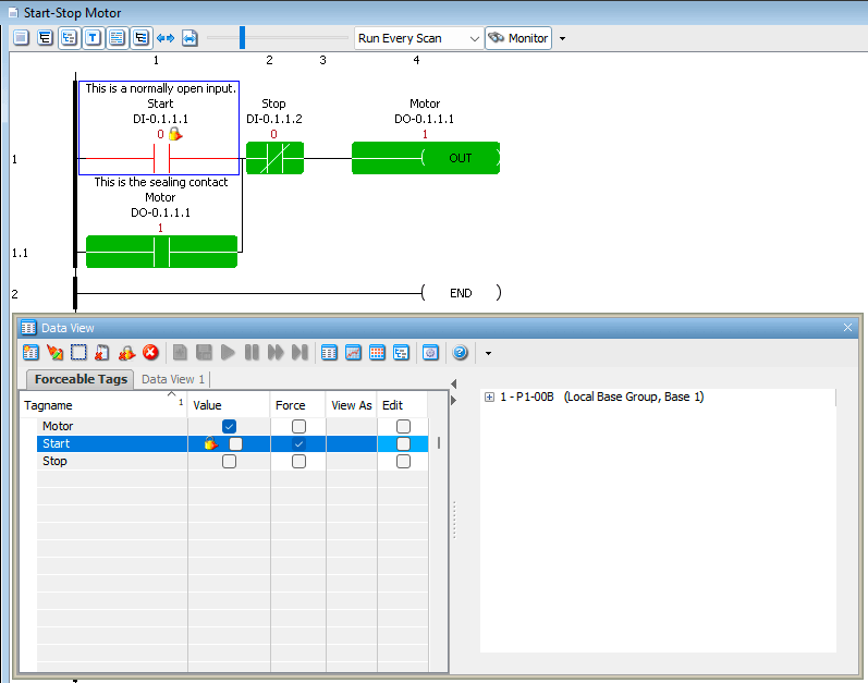
Our program will reflect the off condition of the force, but still show the start as being forced off by the lock icon.
Removing Forces
To remove a force from a bit, uncheck the Force checkbox for that tag and click Send Edit(s). The lock icon will disappear, and the bit will return to reflecting its actual physical state.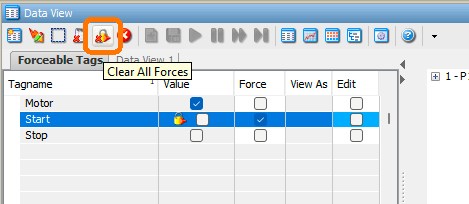
Important Note on Forcing: Forces are powerful troubleshooting tools, but always remember to remove them before leaving the machine. A forgotten force can cause unexpected behavior and safety issues.
Monitor a Rung in Data View – Mini PLC
The Productivity Suite software will also allow us to create a data view tab by selecting the rung or rungs and right-clicking to show the menu.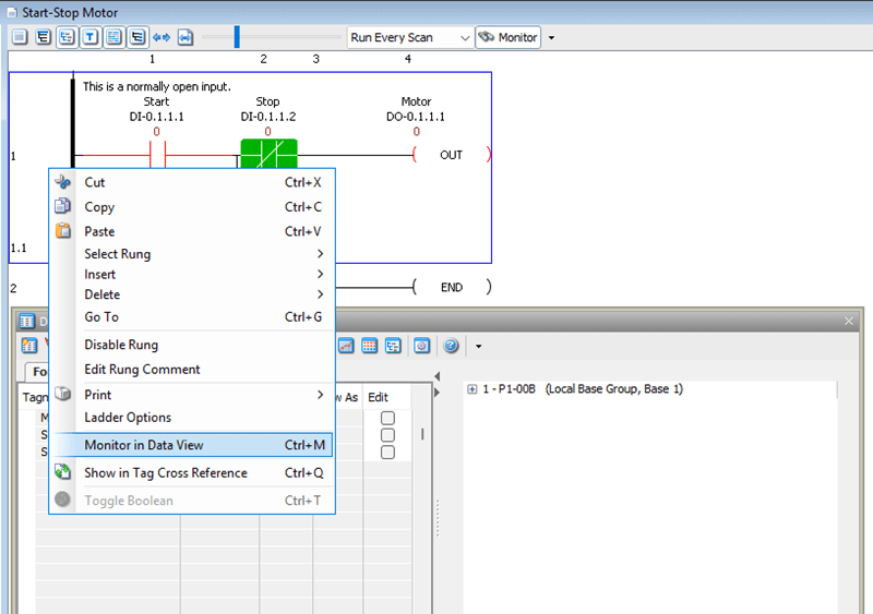
Select “Monitor in Data View”
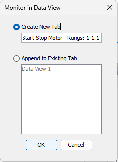
A window will appear, allowing you to either create a new tab or append to an existing one. This will allow us to combine all tag names into a single section of our program for testing and monitoring.
In our case, we will create a new tab. Select OK.
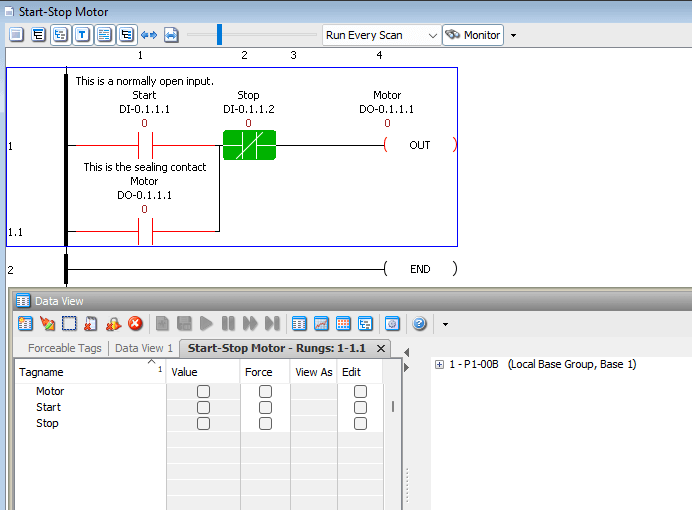
Our tag names for the rungs are displayed in a new Data View tab. For our start-stop circuit, this includes:
- DI-0.1.1.1 (Start Input)
- DO-0.1.1.1 (Motor Output / Seal Contact)
- DI-0.1.1.2 (Stop Input)
This is extremely useful when troubleshooting—you can see all related tags in one organized view.
IO View – Mini PLC Monitoring Program
The Toggle IO View lets you test all of your system’s inputs and outputs before running your program. 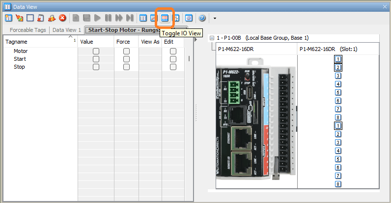
Select the plus sign next to the base unit name. A picture of the P1 Mini PLC will be displayed. The inputs and outputs for this PLC will also be shown. We can set the outputs by clicking the output bit.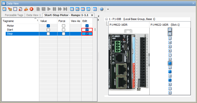
For the P1-M622-16DR Mini PLC, the IO View will show:
- 8 DC Inputs (DI-0.1.1.1 through DI-0.1.1.8)
- 8 Relay Outputs (DO-0.1.1.1 through DO-0.1.1.8)
This is a great way to verify your wiring before running the actual program. You can:
- Toggle each physical input and watch it change in the IO View
- Click on outputs in the IO View to manually energize the relays
- Verify all connections are correct before putting the system into automatic mode
Graph View – Mini PLC Monitoring Program
The Toggle Graph View option allows you to graph tag values. This is an excellent way of troubleshooting your PLC logic. 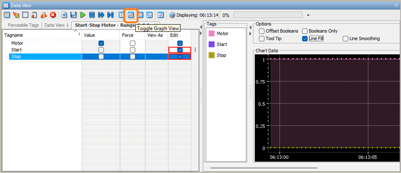
Click and drag your Tagnames over to the Tags in the Graph view to start graphing the values.
See the help menu for all of the different options for the graphing functions.
The Graph View is particularly useful for:
- Timing analysis of your logic
- Seeing the sequence of events when inputs change
- Troubleshooting intermittent issues
- Documenting the behavior of your program
For our start-stop circuit, you could graph all three tags (Start, Stop, Motor) and see the exact timing relationship between pressing Start, the motor turning on, the seal contact engaging, and the response to the Stop input.
Dataview Options…
The data view options menu icon will bring up the Options window as we did at the beginning of this post. 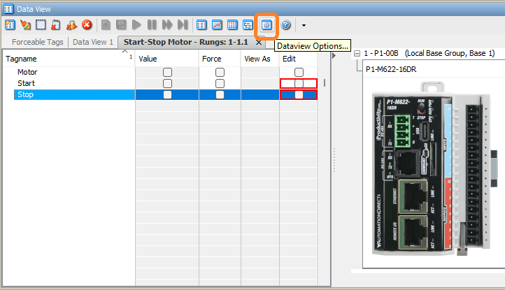
You can change different colors and options for the Data View window.
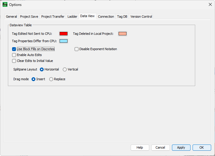
Select “Use Block Fills on Discretes” and click “Apply” and then “OK”.
You will now see that the value when ON (checked) will be a solid green block. This makes it much easier to quickly scan a list of tags and see which ones are active.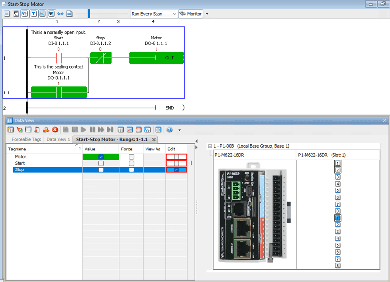
Now that we understand some of the monitoring tools, let’s put them to use, testing our start-stop motor circuit on the P1-M622-16DR:
Test 1: Force Testing
- Open Data View and find DI-0.0.0.1 (Start)
- Check Edit and Force, then click Send Edit(s)
- Verify the motor output turns ON even without pressing the physical button
- Uncheck Force and click Send Edit(s) to remove the force
- Motor should turn OFF (unless physically sealed)
Test 2: Stop Override
- Force the Start input ON
- Force the Stop input ON (this simulates pressing Stop)
- Verify Motor turns OFF—Stop should always override Start
- Remove all forces when done
Watch the video below to see how we can monitor and test the program in our Productivity Mini PLC P1-M622-16DR.
Productivity Mini PLC P1-M622-16DR from AutomationDirect
Overview Link (Additional Information on the Unit)
Configuration (Configure and purchase a system – BOM)
User Manual and Inserts (Installation and Setup Guides)
Productivity Suite Programming Software (Free Download Link)
This software includes all instruction sets and help files for the Productivity Series.
Next time, we will look at wiring our physical inputs and outputs and monitor our ladder logic in the Productivity Mini PLC P1-M622-16DR.
The Productivity Mini PLC series from AutomationDirect, and specifically, the P1-M622-16DR, is a compact powerhouse that packs serious capability into a surprisingly small footprint. To see our first ladder logic, click here. Click here to build digital twins of 3D virtual machinery, test control logic, and learn automation without expensive hardware, using Machine Simulator.
Watch on YouTube: P1-M622-16DR Mini PLC Monitoring and Testing the Program!
If you have any questions or need further information, please contact me.
Thank you,
Garry
Related Posts:
- Stop Struggling! Master Productivity 1000 PLC Debugging Tools
- How to Make a Start-Stop Jog Circuit in a PLC
- P1-M622-16DR Mini PLC First Program
There are many PLC manufacturers offering various hardware and software. All programmable logic controllers share similar basic features. Here is how I would approach learning about basic PLCs.
Once you are familiar with the basics of the PLC, you will learn the specifics of the controller you will be programming.
This is the easiest way to learn about PLC programming.
Here are the controllers that we have covered or are covering at ACC Automation:
LS Electric XGB PLC Series
BRX Do-More Series (Do-More Designer Software + Simulator)
Productivity Series P1000 / P2000
Click PLC Series
Omron CP1H Series
Horner XL4 PLC Series
Arduino Opta PLC
The EasyPLC Software Suite is a comprehensive package that includes PLC, HMI, and machine simulator software. This allows you to make a digital twin. See below to receive 10% off this software. This PLC learning package contains the following:
Easy PLC – PLC Simulation will allow programming in Ladder, Grafcet, Logic Blocks, or Script.
HMI System – Easily create a visual human-machine interface (HMI)
Machine Simulator – A virtual 3D world with real-time graphics and physical properties. PLC programs can be tested using the EasyPLC or through other interfaces. (Modbus RTU, TCP, etc.)
Machine Simulator Lite – Designed to run on Android Devices.
Machine Simulator VR – Virtual Reality comes to life so you can test, train, or practice your PLC programming.
Purchase your copy of this learning digital twin package for less than $95 USD for a single computer installation or less than $110 USD to allow access on multiple computers.
Receive 10% off the investment by typing in ACC in the comment section when you order.
Learn PLC programming the easy way. Invest in yourself today.
Examples of PLC program development using the five steps.
Click PLC – Easy Transfer Line Programming – Video
Productivity PLC Simulator – Chain Conveyor MS – Video
Five Steps to PLC Program Development – Die Stamping
PLC Programming Example – Process Mixer
PLC Programming Example – Shift Register (Conveyor Reject)
PLC Programming Example – Paint Spraying
PLC Programming Example – Delay Starting of 7 Motors
PLC Programming Example – Pick and Place
PLC Programming Example – Sorting Station (Shift Register)
PLC Programming Example – Palletizer
If you’re like most of my readers, you’re committed to learning about technology. The numbering systems used in PLCs are not difficult to understand. We will walk through the numbering systems used in PLCs. This includes Bits, Decimals, Hexadecimal, ASCII, and Floating Points.
To get this free article, subscribe to my free email newsletter.
Use the information to educate others on how numbering systems work. Sign up now.

The ‘Robust Data Logging for Free’ eBook is also available as a free download. The link is included when you subscribe to ACC Automation.