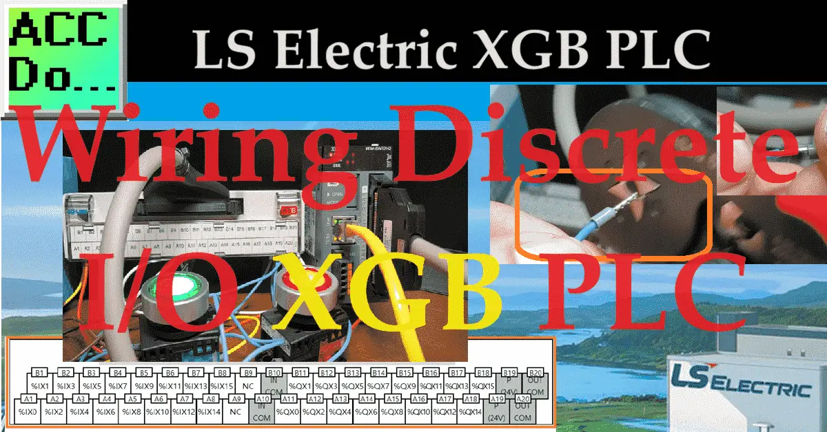
We will be wiring discrete inputs and outputs to an XGB PLC. This will be a lighted pushbutton start and stop. In industrial automation, Programmable Logic Controllers (PLCs) are crucial in controlling various machines and processes. One of the most widely used PLCs is the LS Electric XGB series, which is known for its reliability and flexibility. We will focus on wiring discrete inputs and outputs to an LS Electric XGB PLC, providing insights and tips for a successful implementation.
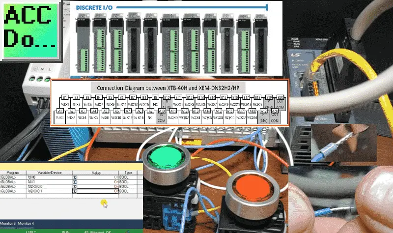
Using the XG5000 programming software, we will connect to the XGB PLC and monitor the physical input locations. Turning on/off the outputs and viewing the inputs will test our wiring and ensure we understand the addresses involved. Let’s get started.
Previously in this LS Electric XGB series, we have done the following:
Transform Automation with LS XGB PLC: The Solution
– Unboxing and Powering Video
Install & Com w/ XG5000 PLC – Video
LS Electric XGB PLC Variables and Scope – Video
See the list of references for the XGB PLC, including the frequently asked questions (FAQ) at the end of this post.
Using Ferrules for Stranded Wiring
When physically wiring inputs to PLC, often these are screw terminals. Using a ferrule when using stranded wire ensures a good connection. Ferrules are any tube used to bind together strands of a material together. In the case of wire ferrules, this tube is crimped to ensure that all wire strands are kept together.
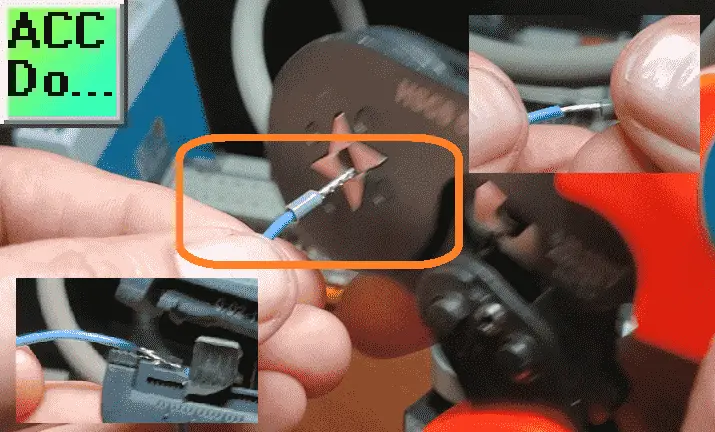
Strip off the end of the wire and place a ferrule on the end, ensuring that all of the wire strands are in the tube. Use the crimping tool to crimp the ferrule tube.
Discrete Inputs
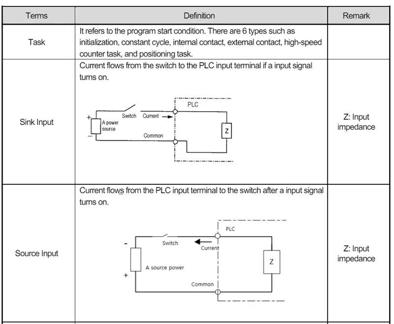
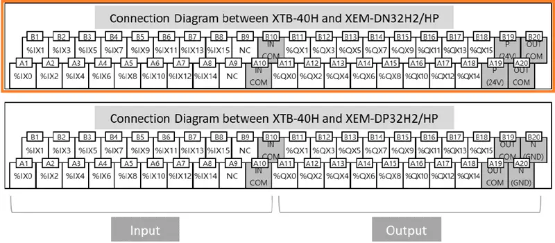
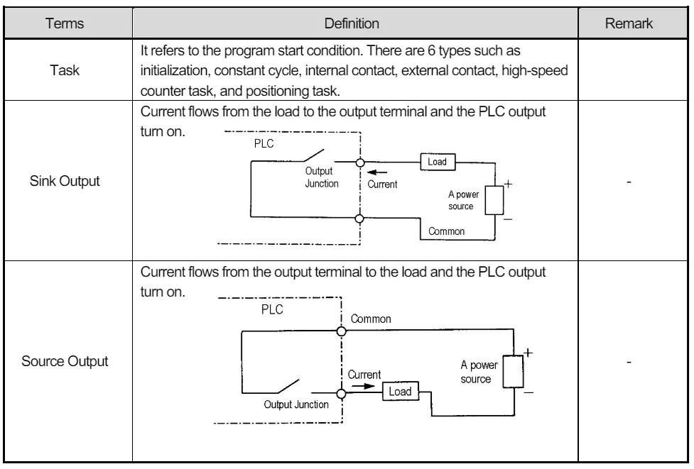
Connecting Sensors and Switches Discrete inputs interface the PLC with various digital sensors and switches, such as limit switches, push buttons, and proximity sensors. These inputs are crucial for monitoring the status of different devices and signaling the PLC to take appropriate actions. When wiring discrete inputs to an LS Electric XGB PLC, following a few key steps is essential to ensure proper functionality. First and foremost, selecting the correct input type with the LS Electric XGB PLC is crucial. DC (direct current) inputs on the CPU can be wired with the common point at 0 VDC (Sinking) or 24 VDC (Sourcing).
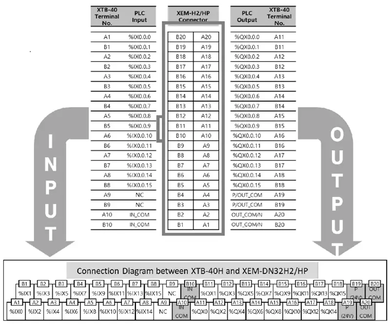
In our case, we will be wiring the commons to 0 VDC for the inputs and outputs. Follow the wiring diagram provided by the manufacturer.
It’s crucial to pay attention to the polarity and voltage specifications when making the connections to prevent damage to the PLC or the connected devices.
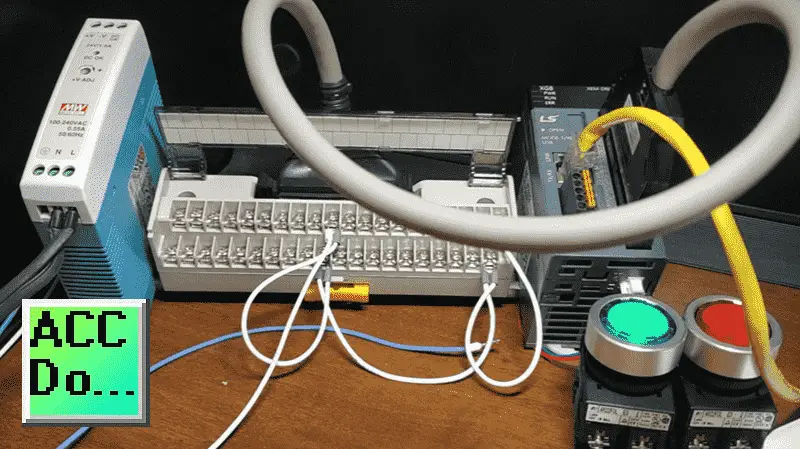
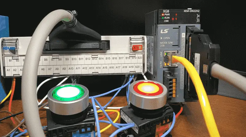
The onboard I/O of the XGB PLC also requires 24 VDC for power. Connect the power according to the manufacturer’s wiring diagram.
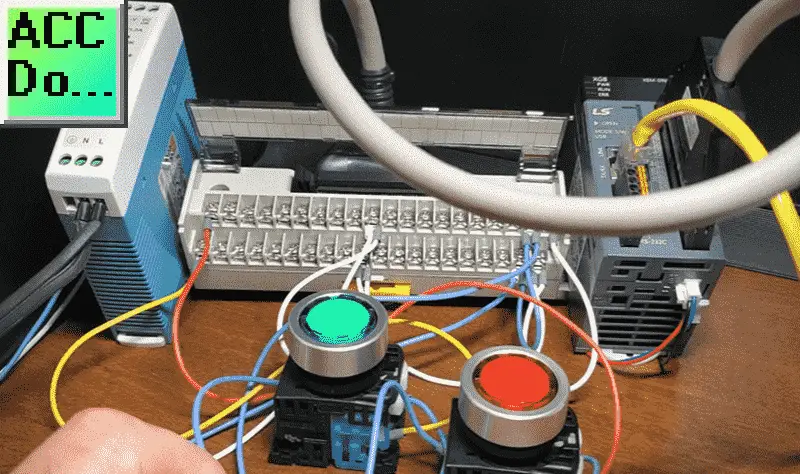
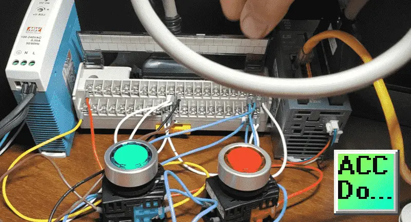
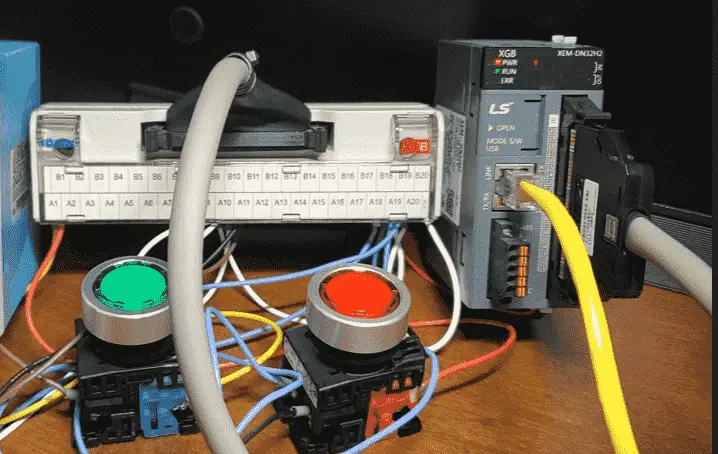
We can now wire the pushbuttons to the PLC input. Starting with the 24 VDC signal wire, we will wire the normally open (NO) of the green switch and the normally closed (NC) of the red switch. One side of each lamp will also be wired to the 24 VDC signal.
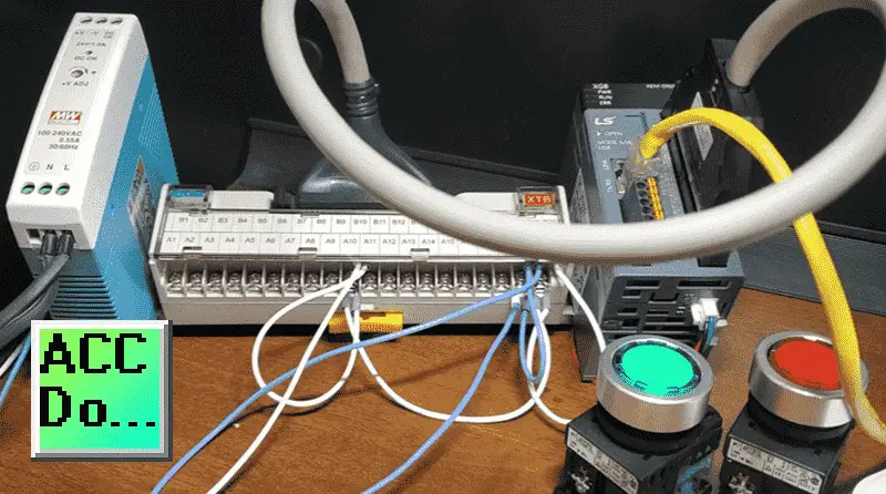
The other side of the normally open green switch will be wired to the first input %IX0. We are using a yellow wire. The other side of the normally closed red switch will be wired to the second input %IX1. We are using a red wire.
The XGB series offers a variety of input modules with different voltage and current ratings to accommodate diverse industrial applications.
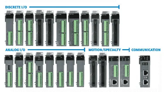
These modules (cards) can be added to your PLC system. Labeling the input terminals and documentation of the wiring scheme can greatly facilitate troubleshooting and maintenance activities in the future. Since this is just for testing, we are using different color wires so you can see the connections.
Discrete Outputs
Discrete outputs control actuators and devices, such as solenoid valves, motor starters, and indicator lamps. These outputs enable the PLC to actuate and supervise different components of a system based on the programmed logic. When wiring discrete outputs to an LS Electric XGB PLC, it’s essential to adhere to best practices to ensure safe and reliable operation. Like discrete inputs, selecting the appropriate output voltage compatible with the LS Electric XGB PLC is the first step in the process. Our CPU outputs on the XGB PLC are sinking. This means that the common for the PLC output is at 0 VDC.
Once again, refer to the manufacturer’s wiring diagram. Our outputs will be the LED lamps with green and red push buttons.
The other contact of the LED lamp for the green light will be wired to the output %QX0 with a brown wire. The other contact of the LED lamp for the red light will be wired to the output %QX1 with a black wire.
Our wiring is complete. Power up the PLC. You will notice that the input 1 is on. This is because it is wired to the normally closed contact of the red push button. If no one touches the switch, the signal is 1, high, or on at the PLC.
The XGB series offers output modules with different current and voltage ratings to meet the requirements of different actuating devices.
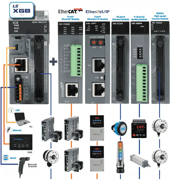
These modules (cards) can be added to your PLC system. Labeling the output terminals and documenting the wiring scheme can greatly facilitate troubleshooting and maintenance activities in the future. Since this is just for testing, we are using different color wires so you can see the connections. It’s also essential to ensure that the connected devices stay within the current capabilities of the output module to prevent overloading and potential damage.
Testing Wiring (Wring Out the Inputs and Outputs)
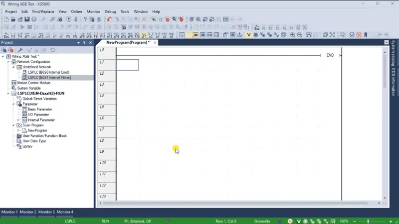
Testing is the next step once the inputs and outputs are wired into the PLC. This is sometimes referred to as wring out the I/O. Start a new project using the XG5000 programming software. We will place an END statement for our program. Set the IP address and connect to the XGB PLC. We have previously covered how this is accomplished in a previous post. You will see the status of our PLC connection at the bottom of the XG5000 programming software. Green means we are connected, and the PLC is running the program. Red means we are connected, and the PLC program is not running. Write our program to the XGB PLC.
Call up Monitor One and enter the input contacts. Activate the monitor icon on the main screen to view the status of the inputs.
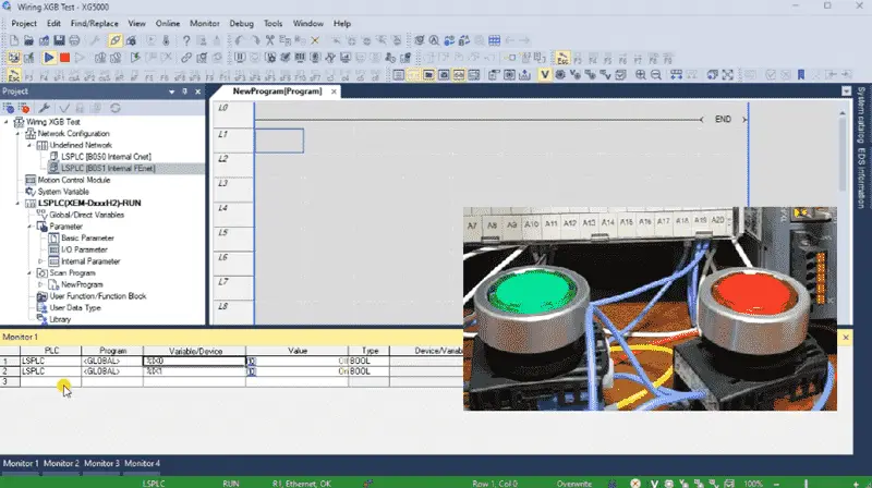
We can now activate the inputs and see the corresponding bits turn off and on.
Add the two outputs to the Monitor One window.
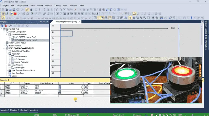
Double-clicking on the output status will allow you to turn them on or off. You will see our green and red LED outputs light. This ensures that our LEDs are wired correctly.
General Tips and Considerations
When wiring discrete inputs and outputs to an LS Electric XGB PLC, several general tips and considerations can enhance the overall installation and operation:
1. Grounding and shielding: Proper grounding and shielding techniques should be employed to minimize electrical noise and ensure signal integrity.
2. Cable routing and protection: Carefully routing and protecting the input and output cables can prevent potential damage and interference from external sources.
3. Safety considerations: Following safety standards and practices is crucial to prevent accidents and ensure a secure working environment.
4. Testing and validation: Thorough testing and validation of the wired inputs and outputs are essential to guarantee proper functionality before integrating them into the more extensive control system.
Wiring discrete inputs and outputs to an LS Electric XGB PLC requires careful planning, attention to detail, and adherence to best practices. By selecting suitable modules, following the provided wiring diagrams, and documenting the installation, you can ensure a reliable and efficient integration of the PLC’s sensors, switches, actuators, and devices. Proper grounding, cable protection, and safety measures further contribute to a successful installation. With these guidelines, you can confidently wire discrete inputs and outputs to an LS Electric XGB PLC for various industrial automation applications.
Watch on YouTube: Wiring Discrete I/O to an XGB PLC
LS XGB PLC Additional Information:
LS XGB PLC – Series
– FAQ – Frequently Asked Questions
Product Cut Sheet (XEM-DN32H2 Unit Specifications)
LS PLC Technical Specifications
Manuals:
Interactive Guide
LS PLC User Manual
Other Documents:
PLC Installation Guide
Product Brochure
PLC Statement of Direction
Software and Support:
XG5000 / XG-PM PLC Programming Software
XEM PLC Firmware
Quick Start Procedures
XEM Pulse Servo Wiring Diagrams
Example Applications Directory
If you have any questions or need further information, please contact me.
Thank you,
Garry
If you’re like most of my readers, you’re committed to learning about technology. Numbering systems used in PLCs are not challenging to know and understand. We will walk through the numbering systems used in PLCs. This includes Bits, Decimals, Hexadecimal, ASCII, and Floating Points.
To get this free article, subscribe to my free email newsletter.
Use the information to inform other people how numbering systems work. Sign up now.

The ‘Robust Data Logging for Free’ eBook is also available for free download. The link is included when you subscribe to ACC Automation.