We will now look at wiring a click plc with selector switch and pushbuttons. A push button (pushbutton) is a simple human interface for controlling some aspect of a machine or process. The push button requires a force to push the button to change the electrical operation from off to on or vice versa. The condition of the output is usually momentarily. Some common everyday pushbuttons we use are keyboards keys.
A selector switch is also a mechanical device that will require a force to turn the electrical operation from off to on or vice versa. The selector switch usually locks into a position.
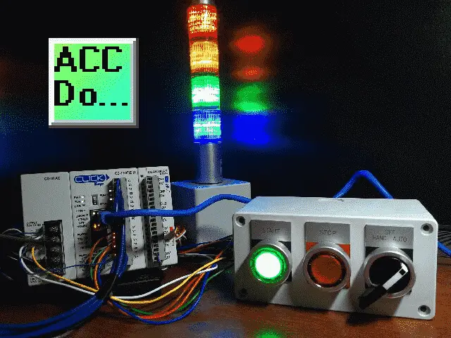
We will be wiring two illuminated pushbutton switches into our Click PLC. A selector switch will also be wired in. Let’s get started.
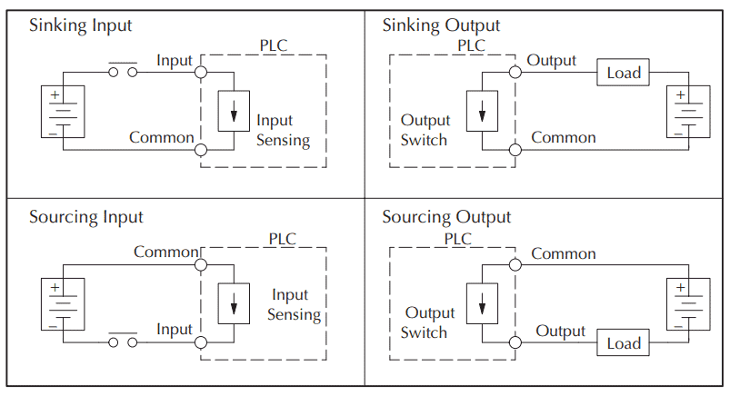
Additional discrete component connections to PLC include the following:
Here’s a Quick Way to Wire NPN and PNP Devices
– Wiring NPN Sensor to PLC Video
– Wiring PNP Sensor to PLC Video
– Wiring Contact Discrete PLC Inputs Video
Wiring Interposing Relays
– Wiring NPN and PNP Sensors into the PLC with an Interposing Relay Video
Click PLC HMI Rotary Encoder Dial Input – Video
Wiring Stack Light to Click PLC – Video
Wiring Push Buttons and Selector Switch
Hardware
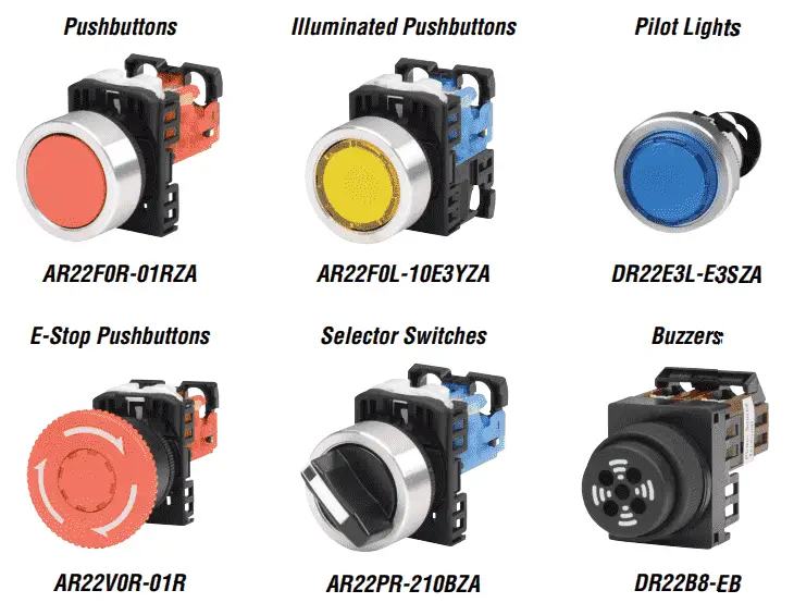
We will be using the Fuji Electric AR22 series of push buttons and selector switch. These are available from Automation Direct. Pilot devices supply simple operator controls and indication for industrial and commercial applications. Fuji Electric 22mm devices are rugged yet economical and include a wide assortment of pushbuttons, indicators, selector switches, and joysticks. The number of contact blocks allowed is device-dependent.
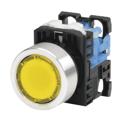
Pushbuttons and selector switches can be ordered as an entire unit, or as individual components.
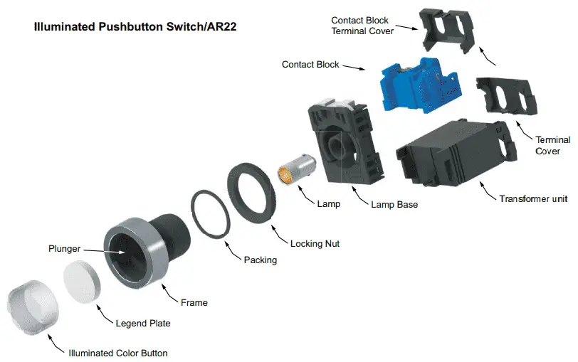
It is important in my opinion to keep the panel all of the same types. This will be easier to maintain and repair.
Pushbuttons and switches are mechanical devices. There is a guideline usually in the manual or specifications of the product that will indicate the life of the device in terms of operations.
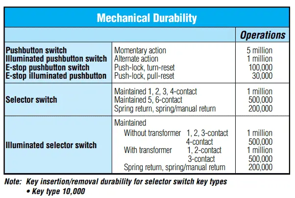
According to the chart above, our illuminated pushbutton switch will have 1 million operations.
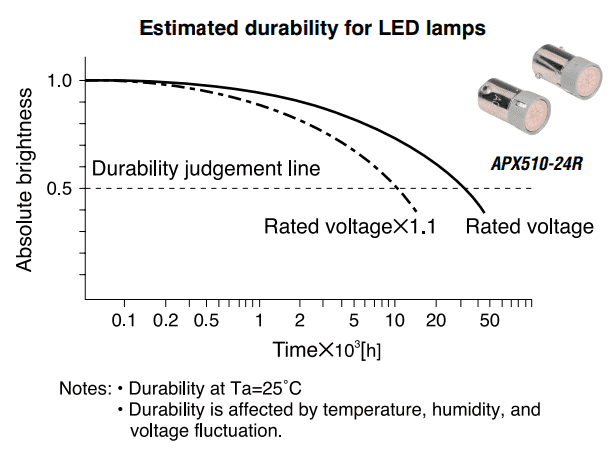
The LED lamps will also have a rated life expectancy. This is based on the brightness of the lamp over time that it is on.
Dimensions
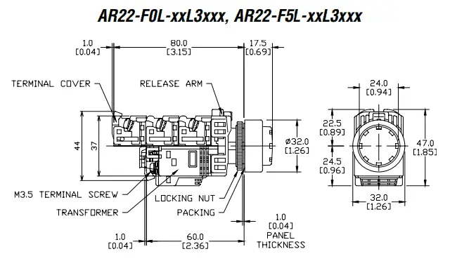
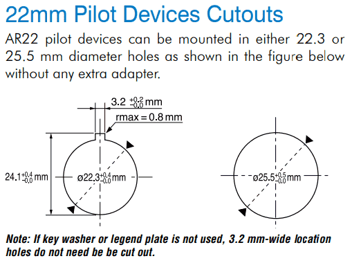
Specific dimensions for devices can be found in the specification guides or manual. These are the dimensions for our hand, off, auto switch.
Contact Blocks
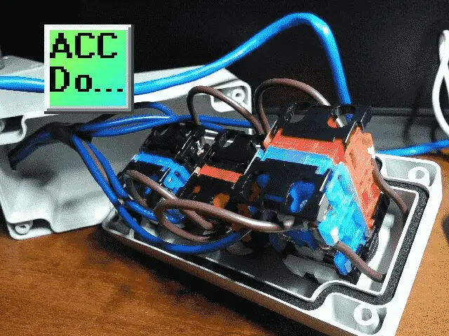
As mentioned above contact blocks can be ordered separately. We can join several contact blocks together on the pushbutton or selector switch. This allows better flexibility with the wiring of the devices.
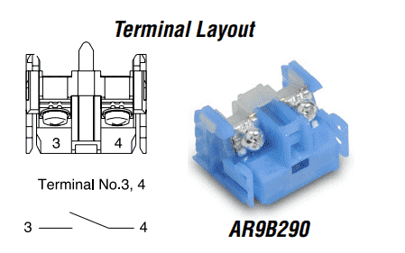
You will see that the contact blocks are colour coded. The blue is a normally open contact. If the pushbutton or switch activates it, the contacts will close.
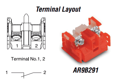
Red is a normally closed contact block. If the pushbutton or switch activates it, the contacts will open.
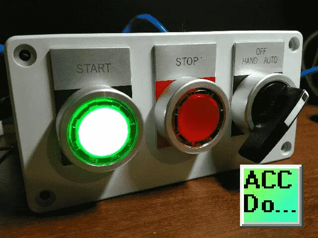
Watch on YouTube: Test and Assembly of Push Buttons and a Selector Switch
Wiring to the Click PLC
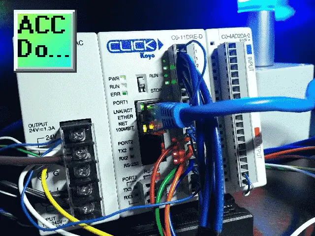
Start PB – X1 – Normally Open
Stop PB – X2 – Normally Closed
Selector Switch Hand Position – X3
Selector Switch Auto Position – X4
Start Green LED Lamp Output – Y5
Stop Red LED Lamp Output – Y6
Click PLC Program Operation – Push Buttons and Switches
We will use our Click PLC program from our Wiring Stack Light to Click PLC post. This program uses Drum Instruction. More information can be found on the use of the Drum instruction at the following post:
Click PLC Drum Instruction
We will now include in our program the pushbuttons and hand-off-auto selector switch that we just wired into the Click PLC.
When the selector switch is in the OFF position the RED LED of the Stop Pushbutton will be illuminated. (ON)
If the selector switch is in the HAND position both PB Lamps will not be on. When the START PB is pressed the four stack lights will be energized. (ON) This will be for the duration of time the start push button is pressed.
If the selector switch is in the AUTO position the Start and Stop LED lamps will operate accordingly with the Drum Instruction. The START PB will start the Drum Sequence and Jog to the next step if it is running. STOP PB will stop and reset the Drum Sequence Instruction. Switching from Auto to Off position will pause the drum sequence.
Click PLC Program

Here is our stop-start circuit. The output will be the Start LED lamp. It is also used to seal itself. If the Start LED lamp is not on and we are not in HAND mode then turn on the Stop LED lamp.
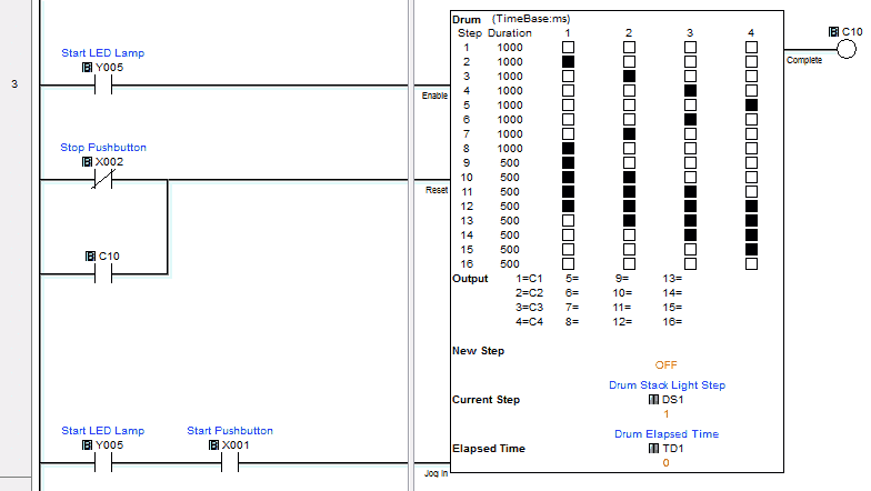
The Drum instruction is enabled with the Start LED Lamp.
The Stop PB or the Drum Complete Bit will reset the Drum Instruction.
When the Drum instruction is enabled and running, the Start PB will allow the Jog function, which will skip to the next step.
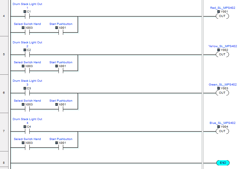
The outputs of the Drum Instruction will turn on the corresponding light output. When the HAND selection switch is ON, the Start PB will turn on the lamps. This is ideal to ensure that the lamps are working correctly.
Monitoring the Click PLC Inputs and Outputs
If the PLC is in a panel and you cannot see the actual inputs and outputs (IO) there is a way to see the status lights. System Monitor is used for doing just that through the Click PLC software.

System Monitor can be accessed through the main menu | Monitor | System Monitor…
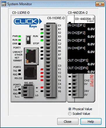
As you run your program the status of the PLC can be monitored.
Please watch the video below to see the operation of the pushbuttons and selector switch with the Click PLC.
Download the Click PLC program here.
Watch on YouTube: Wiring Push Buttons and Selector Switch to Click PLC
Here is some additional information on wiring PLC inputs.
Wiring NPN Sensor to PLC
https://youtu.be/Z09l3HKMpqs
https://accautomation.ca/heres-a-quick-way-to-wire-npn-and-pnp-devices/
Wiring PNP Sensor to PLC
https://youtu.be/nP33k5e_Y-k
https://accautomation.ca/heres-a-quick-way-to-wire-npn-and-pnp-devices/
Wiring Contact Discrete PLC Inputs
https://www.youtube.com/watch?v=xh5dE2Z09d0
https://accautomation.ca/how-plc-inputs-work/
Wiring Stack Light to Click PLC
https://accautomation.ca/wiring-stack-light-to-click-plc/
https://youtu.be/gwDIVtNSXfs
If you have any questions or need further information please contact me.
Thank you,
Garry
If you’re like most of my readers, you’re committed to learning about technology. Numbering systems used in PLC’s are not difficult to learn and understand. We will walk through the numbering systems used in PLCs. This includes Bits, Decimal, Hexadecimal, ASCII and Floating Point.
To get this free article, subscribe to my free email newsletter.
Use the information to inform other people how numbering systems work. Sign up now.
The ‘Robust Data Logging for Free’ eBook is also available as a free download. The link is included when you subscribe to ACC Automation.

