Every Opta IoT PLC comes with the ability to be programmed using the professional series Arduino PLC IDE. (Arduino PRO) This is designed to implement industrial machine control functions and programming, including ladder logic. The Opta hardware is also designed to support industrial voltages.
This quick start guide will show you how to wire, initialize, license, and write your first ladder logic program in the Opta IoT PLC. A proximity sensor will be wired to the first input of the Opta PLC. Ladder logic will program the controller to turn on the first relay output when the proximity sensor is activated. Let’s get started with this Opta quick start.
The entire Arduino Opta IoT PLC Series is located here.
Previously in this series, we have discussed the following:
Opta Introduction Video
Arduino Opta IoT PLC Cutting Edge Hardware – Video
Arduino Opta Software Installation – Video
Note: A post is usually associated with each video. This will provide additional details and links discussed.
Wiring the Opta IoT PLC – Installing an input device
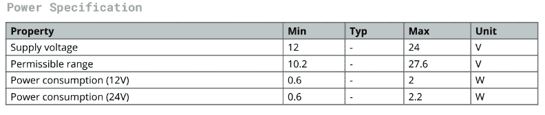
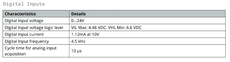
Using the datasheet for the Opta IoT PLC, we will use the following:
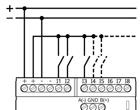
The supply voltage will be 24VDC
The inputs will be discrete (on/off). (Switching to +DC voltage) Since the controller input common is at 0 VDC, this is a sinking input. Here is a post covering the wiring of NPN and PNP 3-wire sensors.
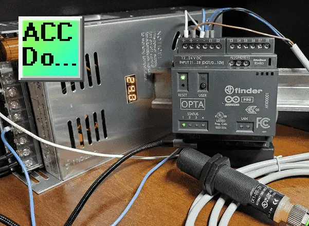
We will be wiring a CK1-00-2H capacitive proximity sensor.
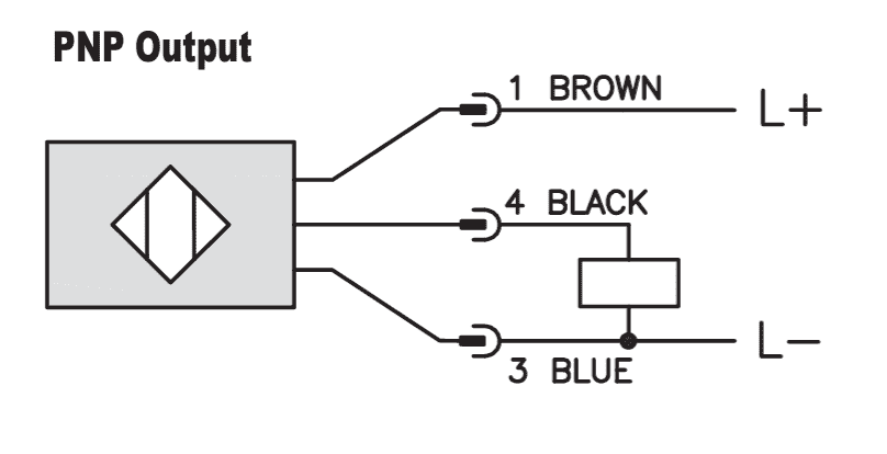
This proximity sensor will be wired as a PNP output. The box that you see in the diagram is the load. Our Opta PLC input will be the load for this sensor.
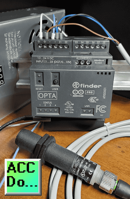
Here is our PNP proximity sensor wired to the Opta IoT PLC input.
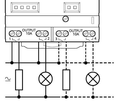
Our output relays are individually isolated from each other.
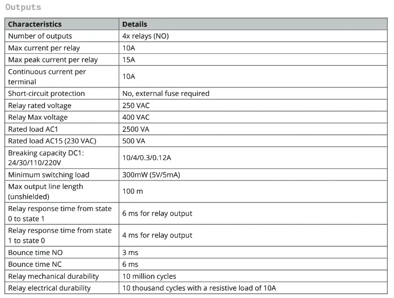
In our quick start example, we will activate the relay and the LED light on the Opta to indicate it is on.
Connection to the Opta IoT PLC (Quick Start)
We assume you have installed the Arduino PLC IDE software on your Windows 10 or newer software system. Call up the programming software using the icon created on your desktop.

Select a new project once the Arduino PLC IDE splash screen disappears and the program has started.
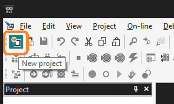
Use the icon or select a new project from the file menu.
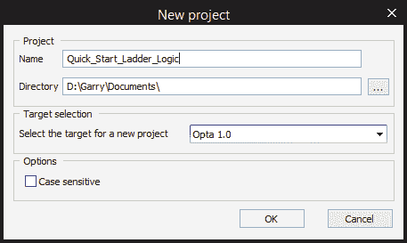
Enter the name of the new project. The directory where your project files will be stored can be changed. Our target is Opta 1.0, which is the default selection. Select OK.
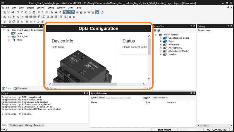
The Opta Configuration will now be displayed. You may have to scroll down to the right to see the options. To the right, under status, it tells us to “Please connect to the target.” We can connect the Opta IoT PLC to our computer using a USB C to USB A cable. Plug in your cable.
NOTE: Not all USB C-type cables are the same. Some are just used for charging. Ensure that the cable used is also used for data.
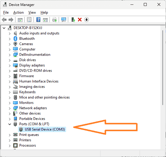
Using the device manager, determine the communication port that the Opta is connected to.
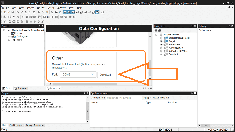
Scroll down within the Opta configuration window until you see the ‘Other’ selection. Select the port number that the Opta is connected to. Select the Download button.
The firmware will be downloaded to the Opta, turning this controller into a PLC.
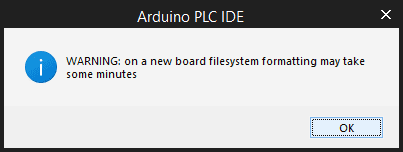
A warning message will be displayed. Select OK.

The PLC IDE software will compile and transfer the sketch to the controller.
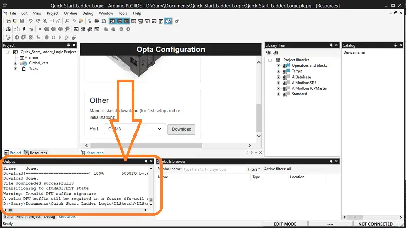
The output window will display the progress of the operation.
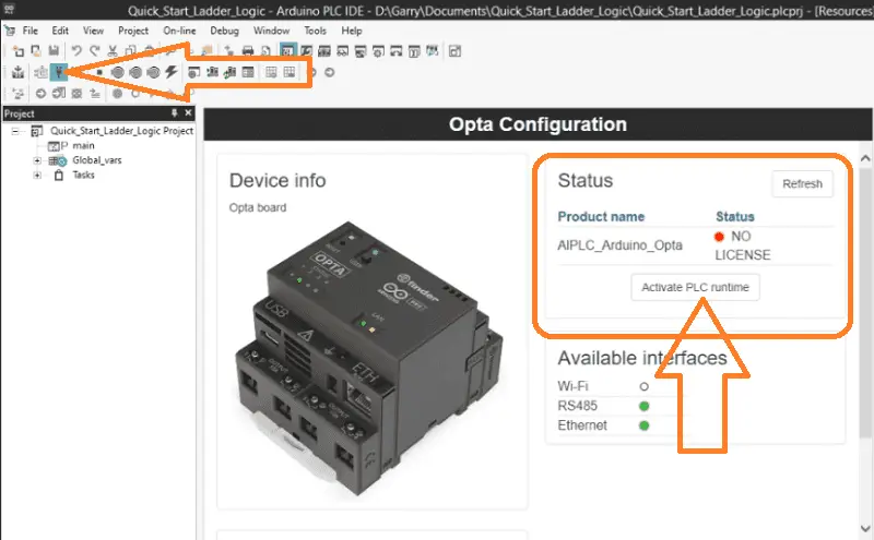
Click the Connect to Target icon in the main menu to confirm your connection to your Opta PLC. If a license has not been activated for this Opta controller, you will see you do not have a license message under the status heading. Select the “Activate PLC runtime” option and follow the prompts to activate your PLC runtime.
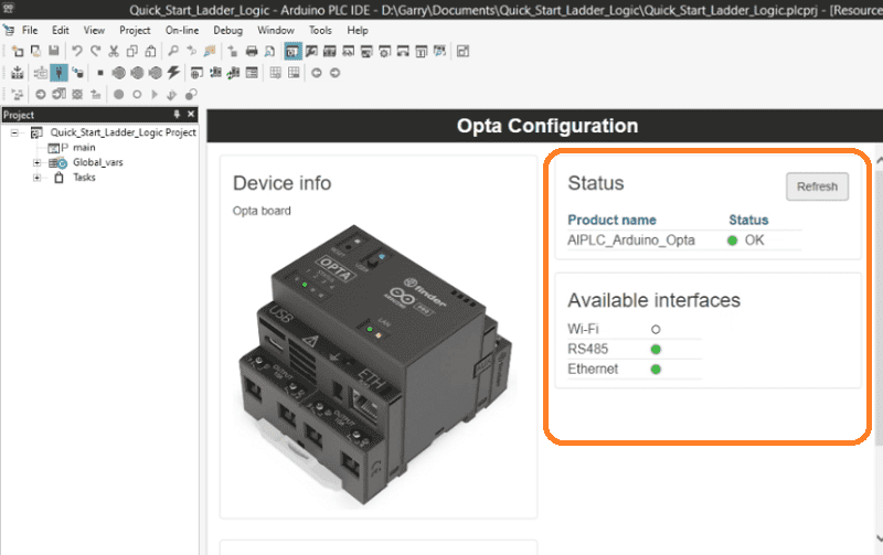
Make sure to disconnect the power to your Opta controller and USB cable before proceeding. Once you have restored power and reconnected the USB cable to the controller, click the refresh button in the status area.
Your Arduino Opta IoT PLC is now ready for you to start programming!
Configuring the Tags (Quick Start)
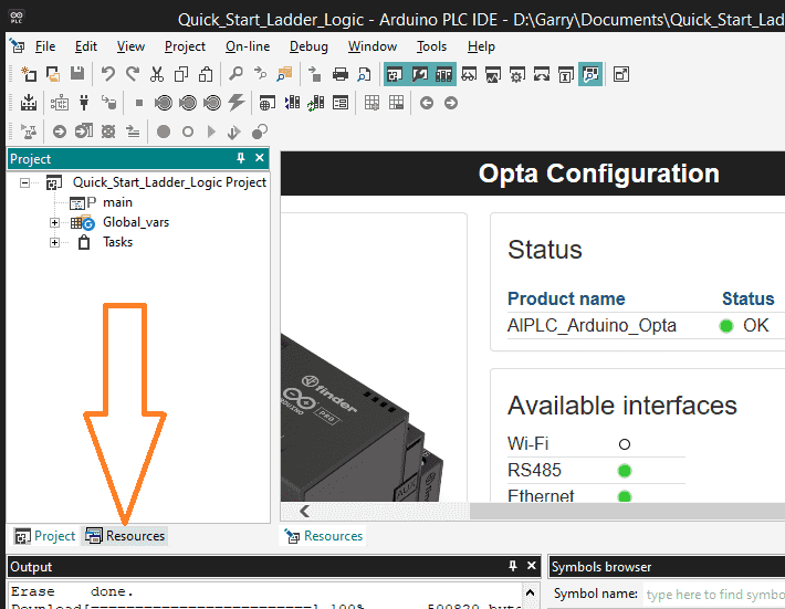
The first thing to do after ensuring that we have communication and the license is active is to assign tag names with the physical inputs and outputs of the Opta PLC. In the workspace window, select the Resources tab at the bottom.
In the resources tab under Local IO Mapping, select programmable inputs.
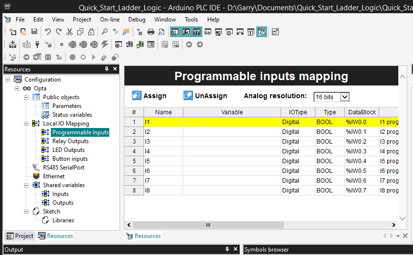
We can now assign a variable to call these inputs.
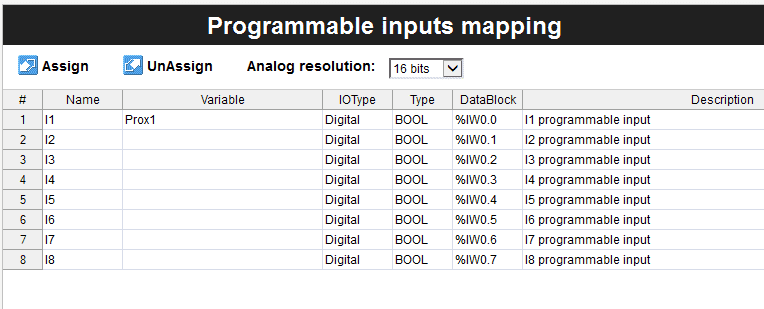
Name the first input I1 Prox1. This will be a digital input type (boolean).
Note: The eight inputs can be boolean (on/off) or analog (range). This is selected under the heading of type.
Select the relay outputs under the local IO mapping.
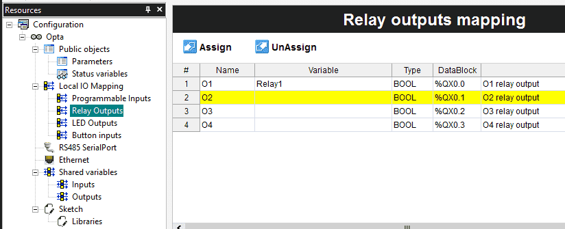
Name the first output O1 Relay1.
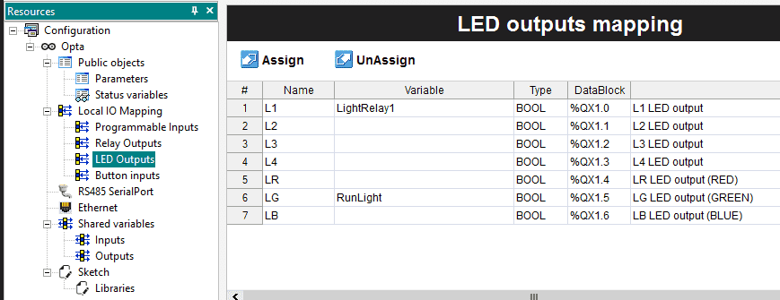
Assign the name LightRelay1 to the first LED output light. This will be used to indicate when our relay is triggered in our program. We also assign the variable RunLight to the Green LED on the controller. This will indicate to the operator that the PLC is running.
Select the Project tab.
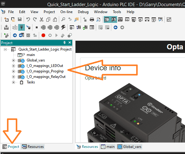
You will now see the variables we have just assigned to the project list.
Tasks and What They Do
To access the tasks in your project, navigate to the project tab and locate the tasks folder.
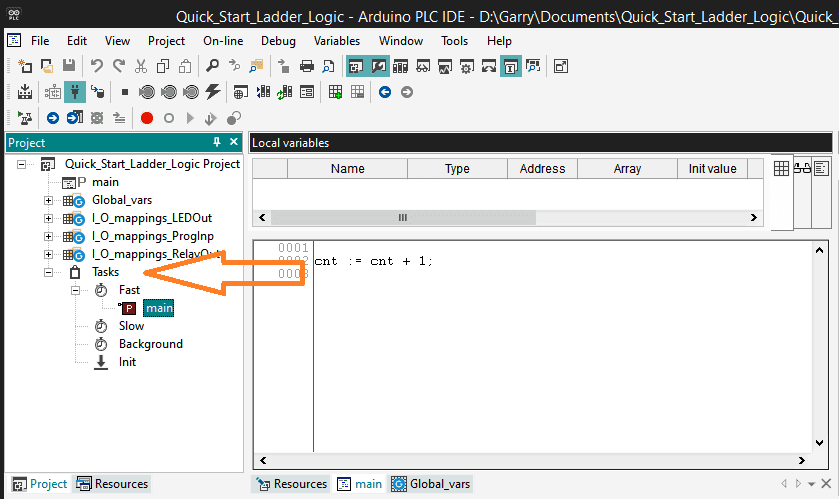
Expand the folder by clicking on the plus sign next to it. The tasks are categorized into Fast, Slow, Background, and Init.
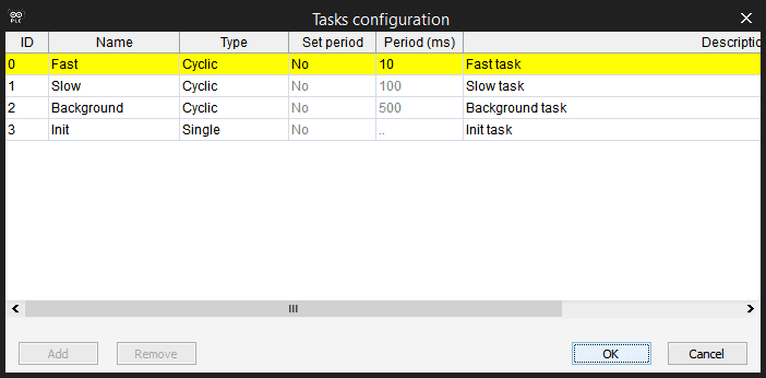
To configure the tasks, right-click on any of the four task folders and select task configuration.
Your programs will be executed within the designated task folders.
The Fast Task folder will execute your programs cyclically every 10 milliseconds. (100 times per second) This can be changed by changing the set period to yes. You can then enter a value in the period column in milliseconds. The majority of programs will be placed in this folder.
The Slow and Background task folders will also scan cyclically. They are both set at a fixed period of 100 and 500 milliseconds. (10 times per second and 2 times per second) These tasks are ideal for functions like math equations, etc.
The Init or Initialize task folder sets variables or conditions in the plc after it powers up. It will run for a single scan.
Select OK to close the task configuration window.
Opta Basic Ladder Logic Program (Quick Start)
To start a new program, right-click on the project name, and select new program under the add heading.
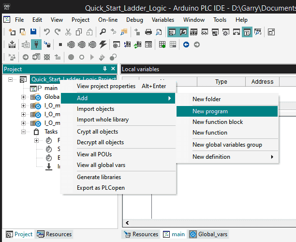
You can also do this by clicking on the project name and from the main menu | Project | New Object | New Program.
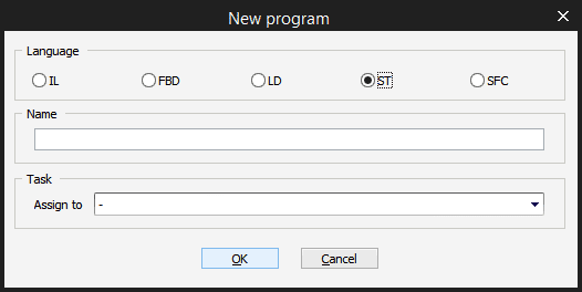
The new program window will be displayed. In our example, we will use a ladder diagram (LD).
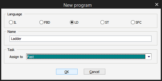
Select LD. Name the new program Ladder and assign it to the fast task folder. Select OK.
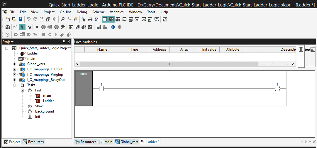
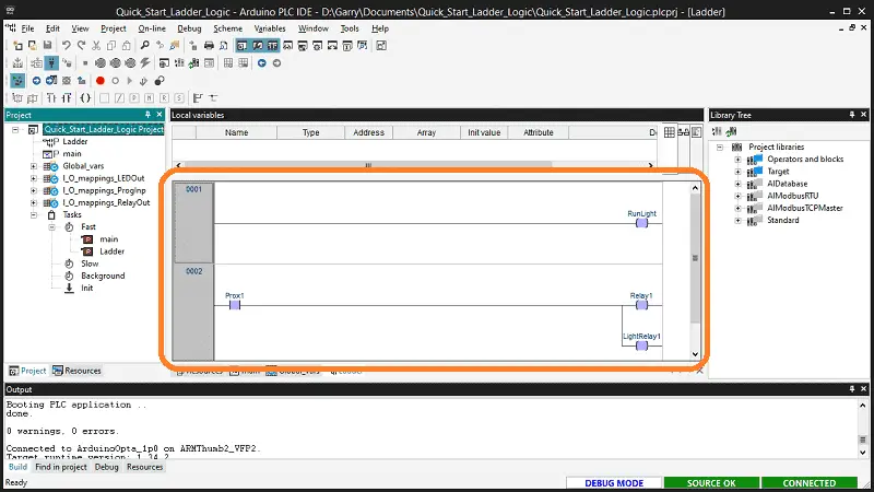
Our new ladder program will now be displayed in the work area. It will contain a single rung with an input and output condition. This program also appears under the fast task folder and under the project as a ladder diagram symbol.
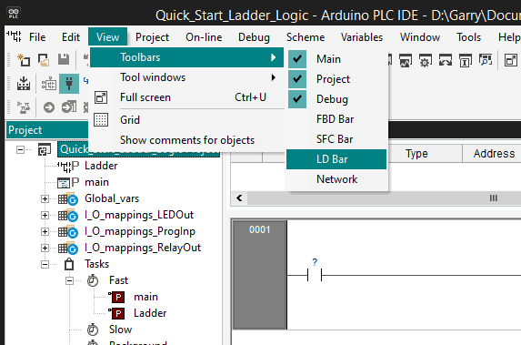
The ladder diagram bar icons can be displayed using the main menu | View | Toolbars| LD Bar. As you will discover, multiple ways exist to move around and enter your program.
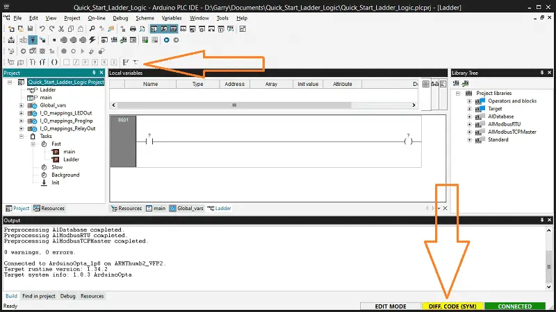
You will now see the ladder toolbar icons displayed. Since we are connected to the Opta PLC, we are in edit mode, and the code differs from the PLC IDE and controller. This is because we just added this ladder program.
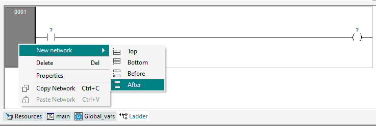
Right-clicking on the rung number will bring up a menu to add, delete, copy, or document the rung.
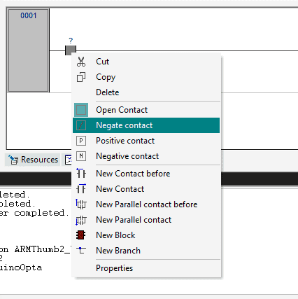
Selecting the contact and right-clicking will allow you to cut, copy, delete, change, or add additional contacts.
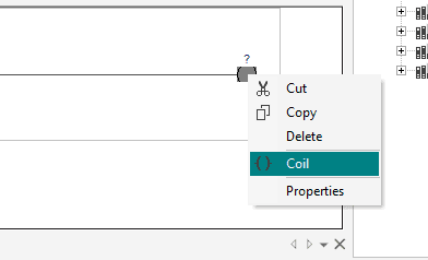
Selecting the output contact and right-clicking will allow you to cut, copy, delete, add, or view the properties of the output.
As you select the elements on the ladder run, you will notice that the LD toolbar also actively displays the available options. As you highlight the toolbar icons, it will show a quick key sequence for the item.
Programming our Ladder Logic with Opta (Quick Start)
Double-clicking on the input contacts in rung one will display the properties window.
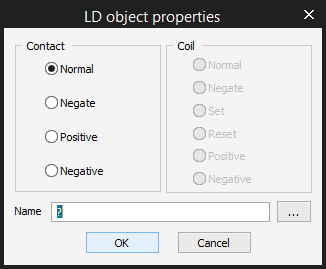
You will see that we can change the contact type and the contact name. Select the three dots to the right of the name.
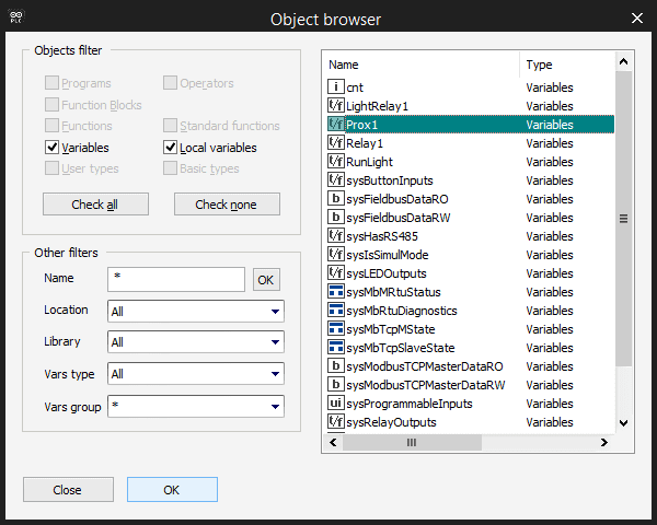
This will call up the object browser window. Select Prox1 for our input contact. Select OK.
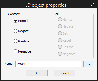
Our proximity tag is then returned to the object properties. Select OK.
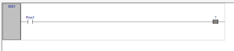
The ladder input contact is now set. Double-click on the output coil in the rung.
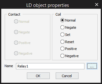
We can change the coil output contact and assign the tag to the coil in the object property window. Select the Relay1 tag for this coil and select OK.
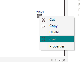
Right-click on the Relay1 coil and select coil. This will add another coil in parallel.
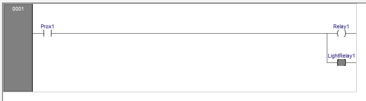
Assign the tag LightRelay1 to this coil.
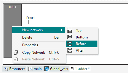
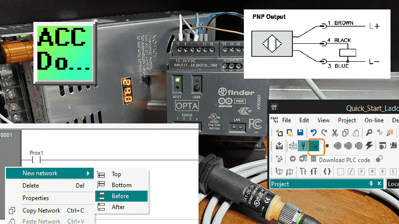
Right-click on the rung and add a new network before this rung. A new rung will not be displayed as rung 1. Select the input contact and press delete. Assign the RunLight tag to the output coil.
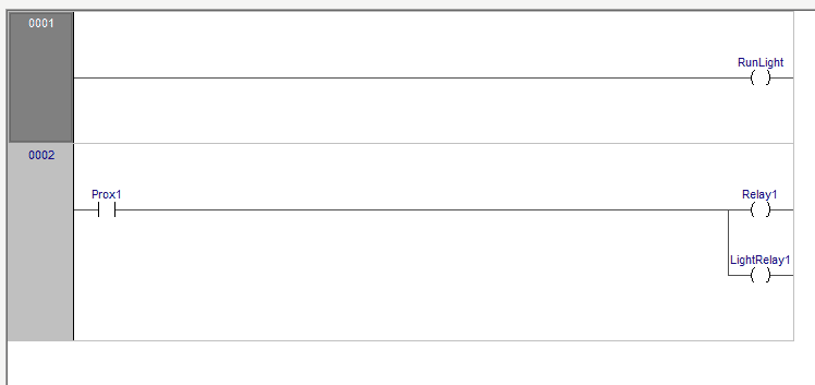
Our ladder logic is now complete.
Download our Ladder Program to the Opta Controller (Quick Start)
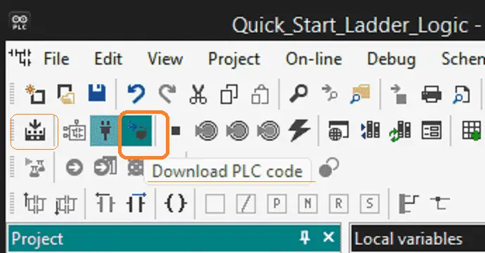
Select the download icon on the main menu.
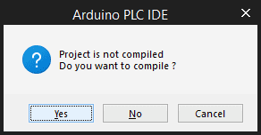
We could have compiled the project first if we wanted. The PLC IDE will prompt you to compile before downloading. This will check your syntax for errors and download our project to the controller. Select Yes.
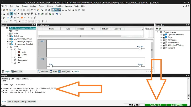
The output window will show you the status of the compile and download operation. When this has finished, the bottom right side of the software will show you that the PLC IDE and controller programs are the same.
Monitoring the Ladder Logic and Variables (Quick Start)
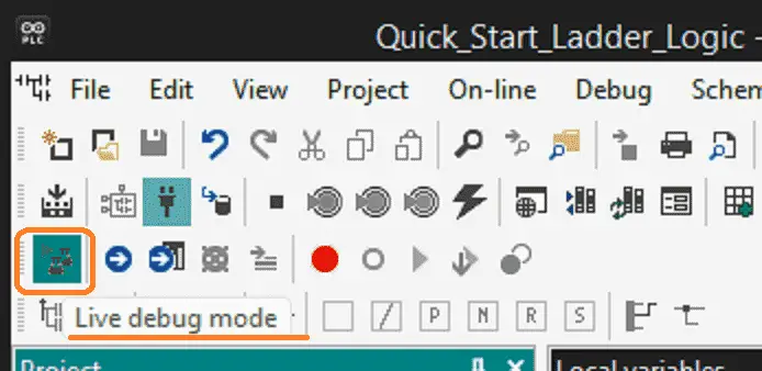
Select the live debug mode icon on the main menu.
This will highlight the inputs and outputs as the program operates.
Visualization is an excellent way to ensure that your program is working correctly.
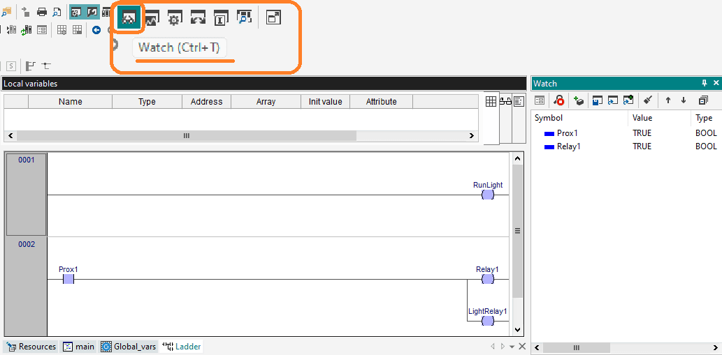
Select the watch icon on the main menu. This will display the watch window. We can enter and select the variables (tags) we want to monitor.
Watch the video below to see this operation with the Arduino Opta IoT PLC.
Download the Opta PLC Sample code used in this post/video here.
Arduino Opta PLC – IoT and Industry 4.0 Enabler
Finder OPTA 8A Series – Tutorials
Datasheet
Quickstart Sheet
Arduino Opta Hardware
Arduino PLC IDE
Arduino Software Download Page
(Arduino IDE, PLC IDE, PLC IDE Tools)
Watch on YouTube: Arduino Opta IoT PLC Quick Start Ladder Logic
If you have any questions or need further information, please contact me.
Thank you,
Garry
If you’re like most of my readers, you’re committed to learning about technology. Numbering systems used in PLCs are not challenging to learn and understand. We will walk through the numbering systems used in PLCs. This includes Bits, decimals, Hexadecimal, ASCII, and Floating points.
To get this free article, subscribe to my free email newsletter.
Use the information to inform other people how numbering systems work. Sign up now.

The ‘Robust Data Logging for Free’ eBook is also available for free download. The link is included when you subscribe to ACC Automation.